trans HONDA CIVIC 2002 7.G Manual PDF
[x] Cancel search | Manufacturer: HONDA, Model Year: 2002, Model line: CIVIC, Model: HONDA CIVIC 2002 7.GPages: 1139, PDF Size: 28.19 MB
Page 465 of 1139
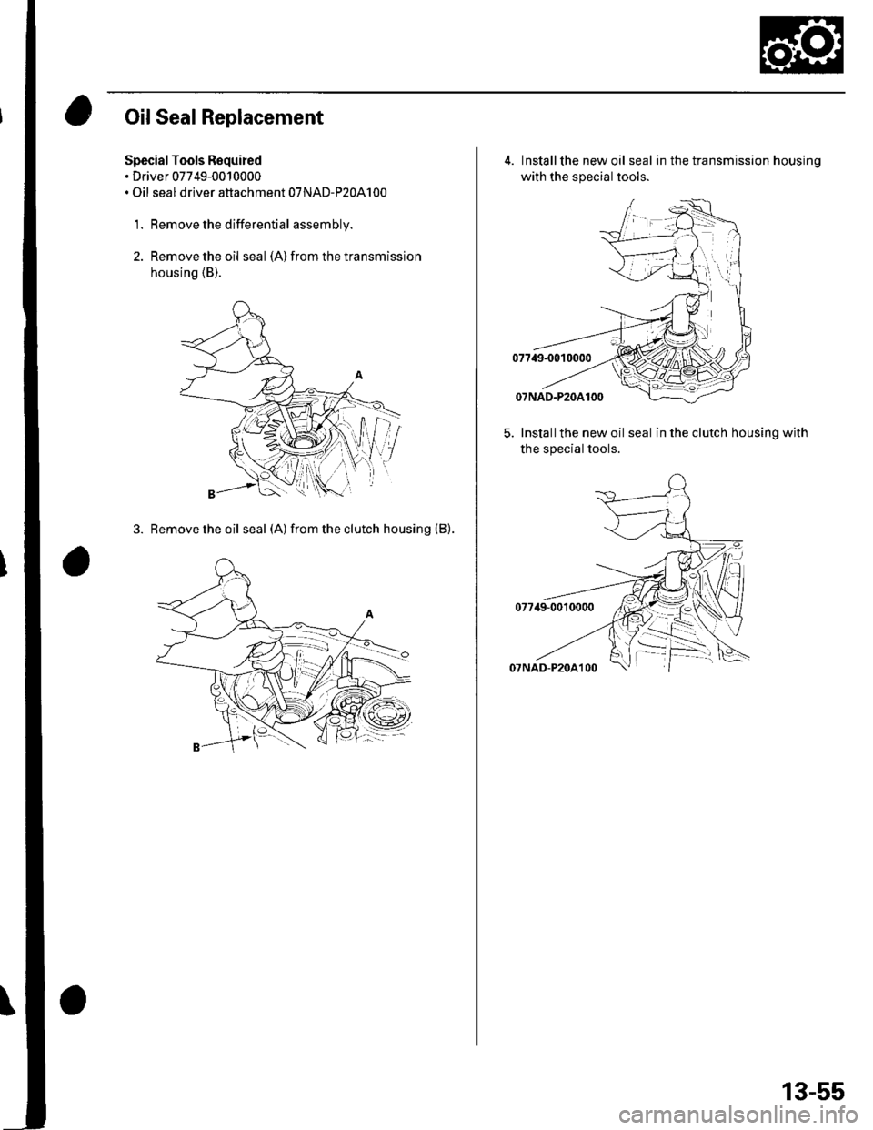
Oil Seal Replacement
Special Tools Required. Driver 07749-0010000. Oil seal driver attachment 07NAD-P20A100
1. Remove the differential assembly.
2. Remove the oil seal (A) from the transmission
housing (B).
3. Removetheoil seal (A) fromtheclutch housing (B).
4. Installthe new oil seal in the transmission housinq
with the special tools.
5. Installthe new oil seal in the clutch housing with
the special tools.
13-55
Page 466 of 1139
M/T Differential
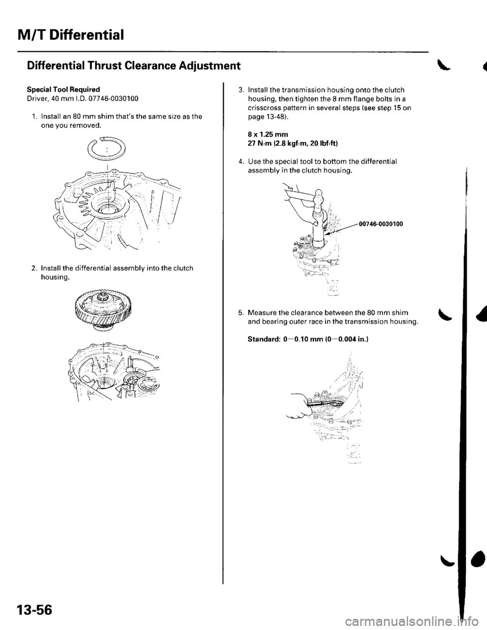
Differential Thrust Clearance Adjustment
SpecialTool Required
Driver. 40 mm LD. 07746-0030100
1. Install an 80 mm shim that's the same size as the
one you removeo.
2.Install the differential assembly into the clutch
housing.
13-56
5.
Install the transmission housing onto the clutch
housing, then tighten the 8 mm flange bolts in a
crisscross pattern in several steps (see step 15 on
page 13-48).
8 x 1.25 mm
27 N m (2.8 kgf'm, 20 lbf.ft)
Use the special toolto bottom the differential
assembly in the clutch housing.
00746-0030100
Measure the clearance between the 80 mm shim
and bearing outer race in the transmission housing.
Standard: 0 0.10 mm l0 0.004 in.)
-i.w.t ..1-- -- :,- -=.
Page 467 of 1139
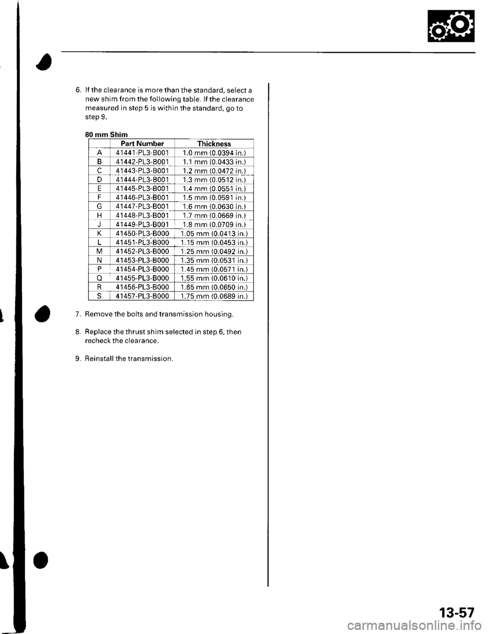
6. lf the clea rance is more than the standard, select a
new shim from the following table. lf the clearance
measured in step 5 is within the standard, go to
step 9.
80 mm Shim
Part NumberThickness
41441 PL3-80011.0 mm (0.0394n.
B41442-PL3-B00111 mm (0.0433n.
c41443-PL3-80011.2 mm (0.0472n.
D41444-PL3-B0011.3 mm {0.0512n.
E41445-PL3-800 11.4 mm 10.0551n.
F41446-PL3-80011.5 mm {0.0591n.
41447-PL3-800 11.6 mm (0.0630n.
rt41448-PL3-B0011.7 mm {0.0669n.
J41449-PL3-80011.8 mm (0.0709n.
41450-PL3-80001 .05 mm (0.0413n.)
41451-PL3-80001 .15 mm (0.0453n.l
tvl41452-PL3-80001.25 mm (0.0492n.l
N41453-PL3-80001.35 mm (0.053'ln.)
P41454-PL3-80001 .45 mm (0.0571n.l
o41455-PL3-80001.55 mm (0.0610n.)
R 41456-PL3-8000'1.65 mm (0.0650 in.)
41457-PL3-80001.75 mm (0.0689 in.)
7.Remove the bolts and transmission housing.
Replace the thrust shim selected in step 6, then
recheck the clearance.
Reinstall the transmission.
8.
9.
13-57
Page 470 of 1139
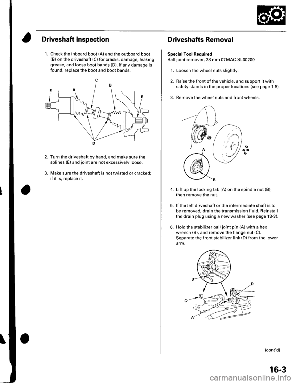
Driveshaft Inspection
1. Check the inboard boot (A) andthe outboard boot(B) on the driveshaft (C) for cracks, damage, leaking
grease, and loose boot bands (D). lf any damage is
found, reDlace the boot and boot bands.
Turn the driveshaft by hand, and make sure the
splines (E) and joint are not excessively loose.
Make sure the driveshaft is not twisted or cracked;
if it is, replace it.
Driveshafts Removal
Special Tool Required
Balljoint remover, 28 mm 07MAC-S100200
1. Loosen the wheel nuts slightly
2. Raise the front of the vehicle, and support it with
safety stands in the proper locations (see page 1-8).
3. Remove the wheel nuts and front wheels.
4.Lift up the locking tab (A) on the spindle nut (B),
then remove the nut.
lf the !eft driveshaft or the intermediate shaft is to
be removed, drain the transmission fluid. Reinstall
the drain plug using a new washer (see page 13-3).
Hold the stabilizer balljoint pin (A) with a hex
wrench {B), and remove the flange nut (C).
Separate the front stabilizer link (D) from the lower
a rm.
(cont'd)
16-3
Page 486 of 1139
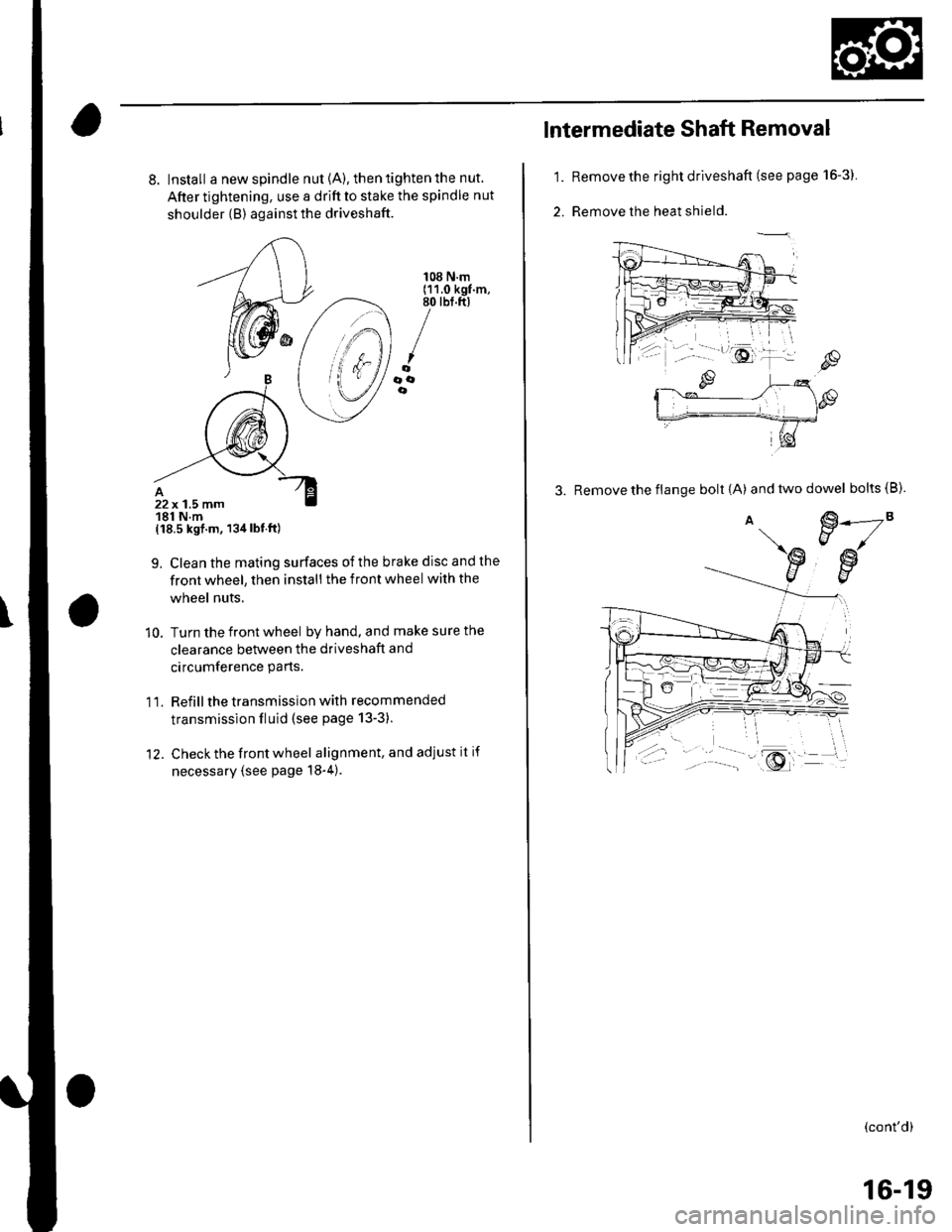
8. Install a new spindle nut {A), then tighten the nut.
After tightening, use a drift to stake the spindle nut
shoulder {B) against the driveshaft.
{18.5 kgf.m, 134lbt.ft)
9. Clean the mating surfaces ofthe brake disc and the
front wheel, then install the front wheel with the
wheel nuts.
10. Turn the front wheel by hand, and make sure the
clearance between the driveshaft and
circumference parts.
1 l. Refill the transmission with recommended
transmission fluid (see page 13-3).
12. Check the front wheel alignment, and adjust it if
necessary (see page 18-4).
108 N.m(11.0 kgf.m,80 tbt.ft)
/oooe
22x 1.5 mm181 N.m
1.
2.
lntermediate Shaft Removal
Remove the right driveshaft (see page 16-3).
Remove the heat shield.
3. Remove the flange bolt {A) andtwodowel bolts(B).
€.---2"EJ/
€w
(cont'd)
16-19
Page 491 of 1139
Driveline/Axle
Intermediate Shaft Reassembly
(cont'd)
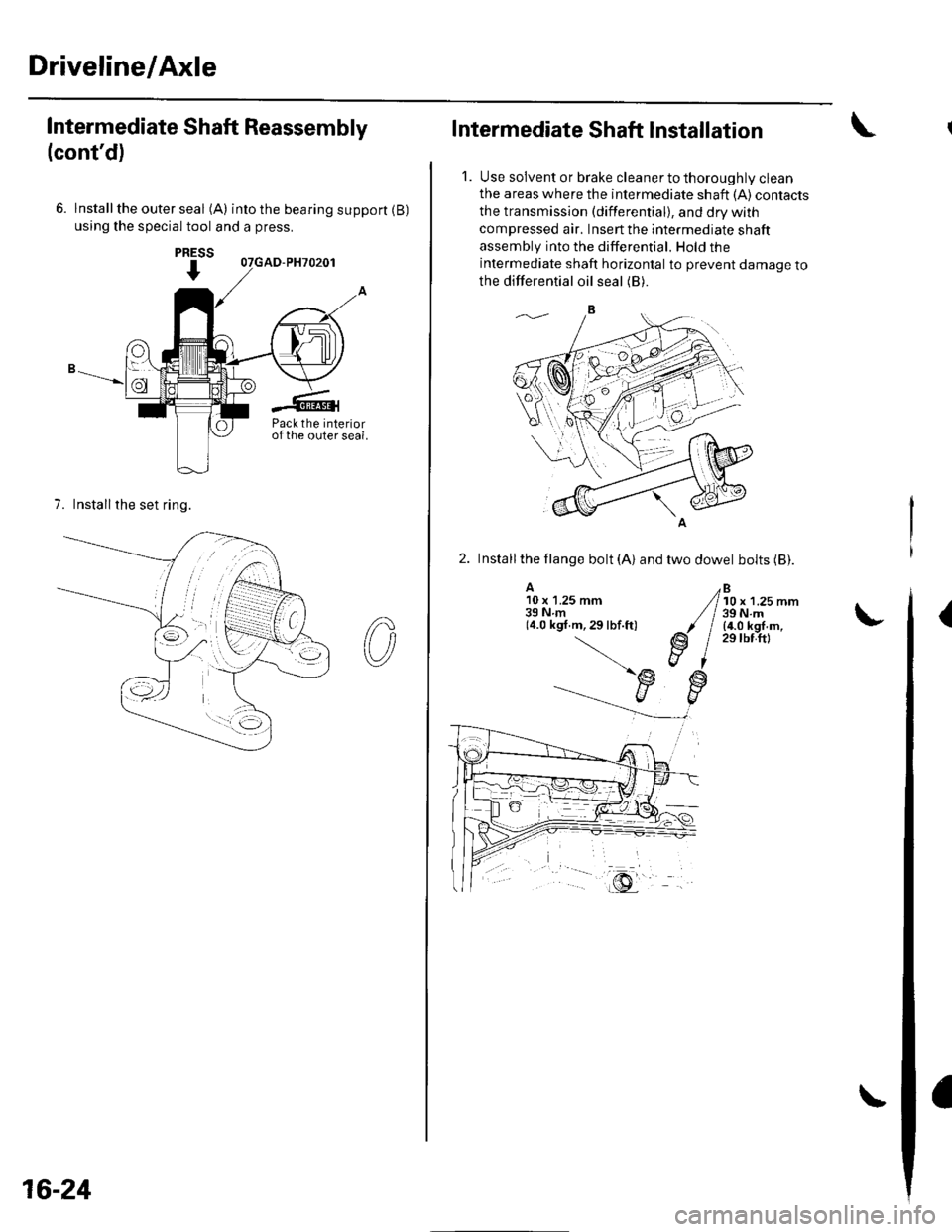
6. lnstallthe outer seal (A) intothebearingsupport(B)
using the special tool and a press.
7. Installthe set ring.
PRESS
I
Pack the interiorofthe outer seal.
16-24
Intermediate Shaft Installation
1. Use solvent or brake cleaner to thoroughly clean
the areas where the intermediate shaft {A) contacts
the transmission (differential), and dry with
compressed air. Insert the intermediate shaft
assembly into the differential. Hold the
intermediate shaft horizontal to prevent damage to
the differential oil seal (B).
2. Installthe llange bolt (A) and two dowel bolts (Bl.
A10 x 1.25 mm39Nm(4.0 kgf.m,29lbf.ft)
Bl0 x 1.25 mm39 N.m(4.0 kgf.m,29 tbf.ftl
(
Page 505 of 1139
Rack Guide Adjustment
Special Tool Required
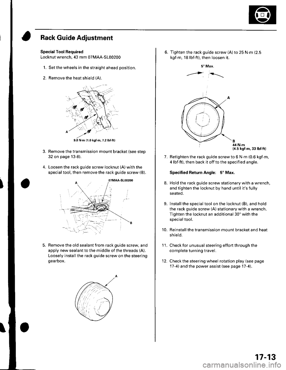
Locknut wrench, 43 mm 07MAA-S100200
1. Set the wheels in the straight ahead position.
2. Remove the heat shield (A).
3.
9.8 N.m (r.0 kgf.m,7.2lbtft)
Remove the transmission mount bracket (see step
32 on page 13-8).
Loosen the rack guide screw locknut (A)with the
special tool, then remove the rack guide screw (B).
Remove the old sealant from rack guide screw, and
apply new sealant to the middle of the threads (A).
Loosely installthe rack guide screw on the steering
gearDox.
'-.i. '' '
07MAA-S100200
6. Tighten the rack guide screw (A)ro 25 N.m (2.5
kgf.m, 18lbf.ft). then loosen it.
5" Max.
j i-rrrr-,
I 4il N.m{a.5 kgf.m,33lbt.ft)
Retighten the rack guide screw to 6 N.m (0.6 kgf m,
4 lbf.ft), then back it off to the specified angle.
Specified Return Angle: 5' Max.
Hold the rack guide screw stationary with a wrench,
and tighten the locknut by hand until it's fully
seated.
Installthe special tool on the locknut (B), and hold
the rack guide screw (A) stationary with a wrench,
Tighten the locknut an additional 30" with the
specialtool.
Reinstall the transmission mount bracket and heat
sh ie ld,
Check for unusual steering effort through the
complete turning travel.
Check the steering wheel rotation play (see page
17-4) and the power assist (see page 17-4).
11.
7.
9.
10.
12.
17-13
Page 599 of 1139
Gonventional Brake Components
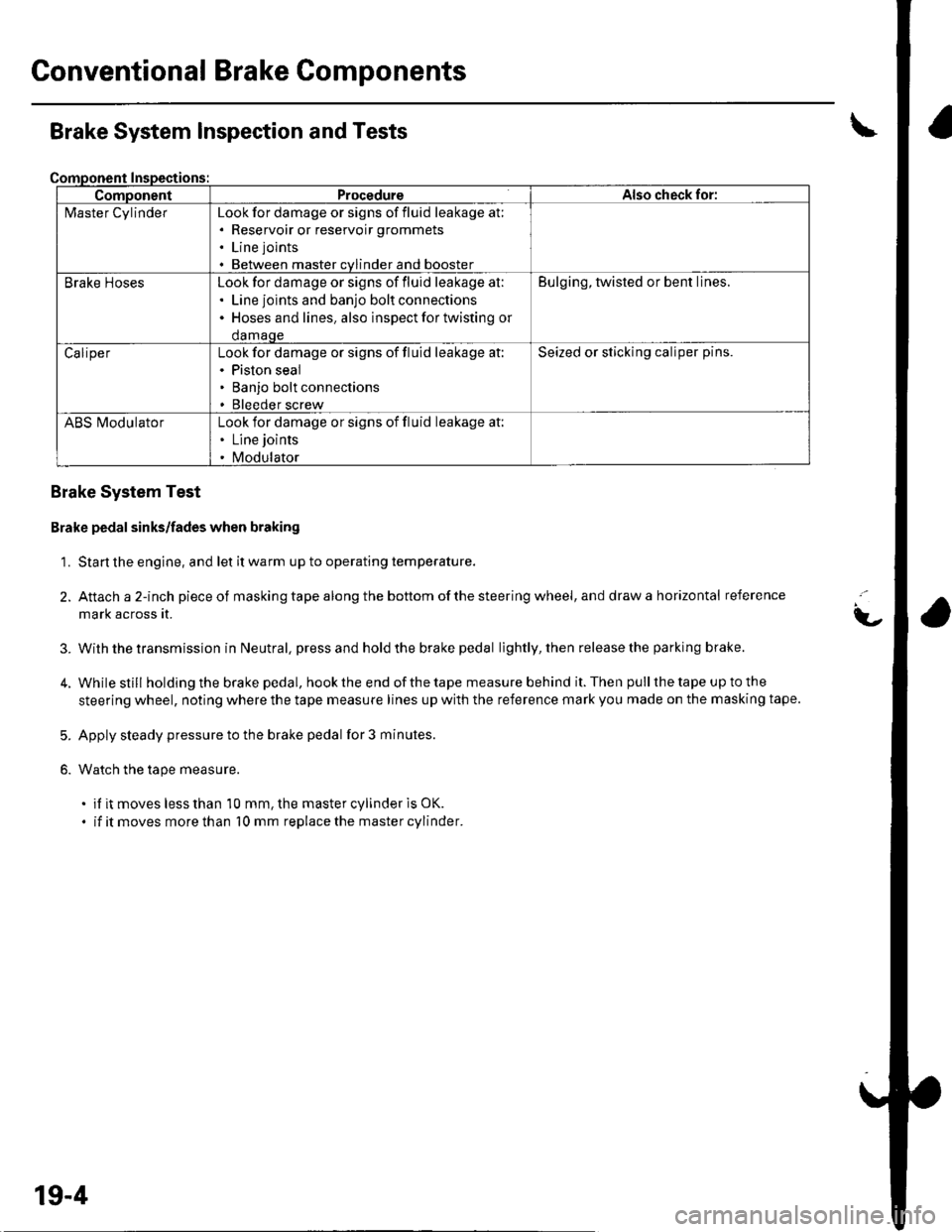
ComponentProcedureAlso check for:
l\4aster CylinderLook for damage or signs of fluid leakage at;. Reservoir or reservoir grommets
. Line joints
. Between master cvlinder and booster
Brake HosesLook for damage or signs of fluid leakage at:. Line joints and banjo bolt connections. Hoses and lines. also inspect for twisting or
damaqe
Bulging, twisted or bent lines.
CaliperLook for damage or signs of fluid leakage at:. Piston seal. Banjo bolt connections. Bleeder screw
Seized or sticking caliper pins.
ABS l\ilodulatorLook for damage or signs of fluid leakage at:. Line joints
. Modulator
Brake System Inspection and Tests
Brake System Test
Brake pedal sinks/fades when braking
1. Start the engine, and let it warm up to operating temperature.
2. Attach a 2-inch pieceof masking tape along the bottom of the steering wheel, and draw a horizontal reference
mark across it.
With the transmission in Neutral, press and hold the brake pedal lightly, then release the parking brake.
While still holding the brake pedal, hook the end of the tape measure behind it. Then pull the tape up to the
steering wheel, noting where the tape measure lines up with the reference mark you made on the masking tape.
Apply steady pressure to the brake pedal for 3 minutes.
Watch the tape measure.
. if it moves less than 10 mm, the master cylinder is OK.
. if it moves more than 10 mm replace the master cylinder.
t-
3.
5.
6.
19-4
Page 633 of 1139
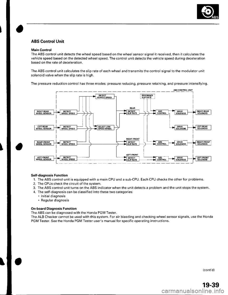
ABS Control Unit
Main Control
The ABS control unit detects the wheel speed based on the wheel sensor signal it received, then it calculates the
vehicle speed based on the detected wheel speed. The control unit detects the vehicle speed during deceleration
based on the rate of deceleration.
The ABS control unit calculates the slip rate of each wheel and transmits the control signal to the modulator unit
solenoid valve when the slip rate is high.
The pressure reduction control has three modes: pressure reducing, pressure retaining, and pressure intensifying.
Self-diagnosis Function
1. TheABScontrol unitisequippedwithamainCPUandasub-CPU.EachCPUcheckstheotherforproblems.
2. The CPUS check the circuit of the system.
3. TheABScontrol unitturns ontheABS ind icator when the unitdetectsa problem andthe unit stops th e system.
4. The self-diagnosis can be classified into these two categories:. lnitial diagnosis. Regular diagnosis
On-board Diagnosis Function
The ABS can be diagnosed with the Honda PGM Tester.
The ALB Checker cannot be used with this system. For air bleeding and checking wheel sensor signals. use the Honda
PGM Tester. See the Honda PGM Tester user's manual for specific operating instructions.
(cont'd)
T---
19-39
Page 768 of 1139
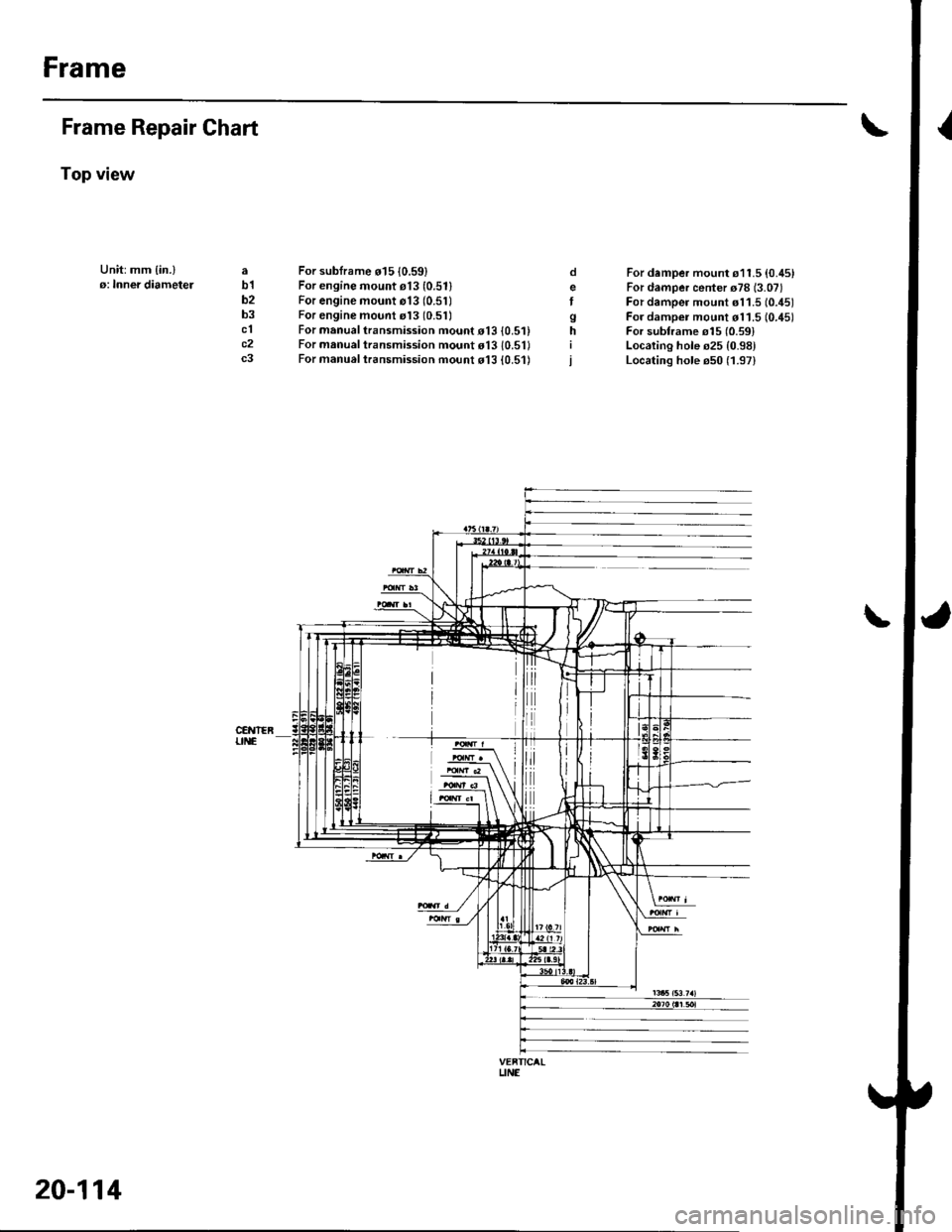
Frame
Frame Repair Chart
Top view
Unit:mm {in.}o: Inner diametelab1b2b3clc2c3
For sublrame o15 10.59)For engine mount e13 (0.511
For engine mount o13 (0.51)For engine mount rl3 (0.51)
For manual transmission mouot o13 {0.5'For manual transmission mount o13 10.5'For manual t.ansmission mo!nt d13 {0.51)
o
Igh
For damper mount s11.5 {0.45}For damper center o78 (3.07)
For damper mount s11.5 (0.451
For dampei mount d11.5 10.45)For subframe o15 {0.591Localing hole s25 {0.98}Locating hole e50 (1.97)
\
VEFTICALUNE
20-114