Motor HONDA CIVIC 2002 7.G Workshop Manual
[x] Cancel search | Manufacturer: HONDA, Model Year: 2002, Model line: CIVIC, Model: HONDA CIVIC 2002 7.GPages: 1139, PDF Size: 28.19 MB
Page 2 of 1139
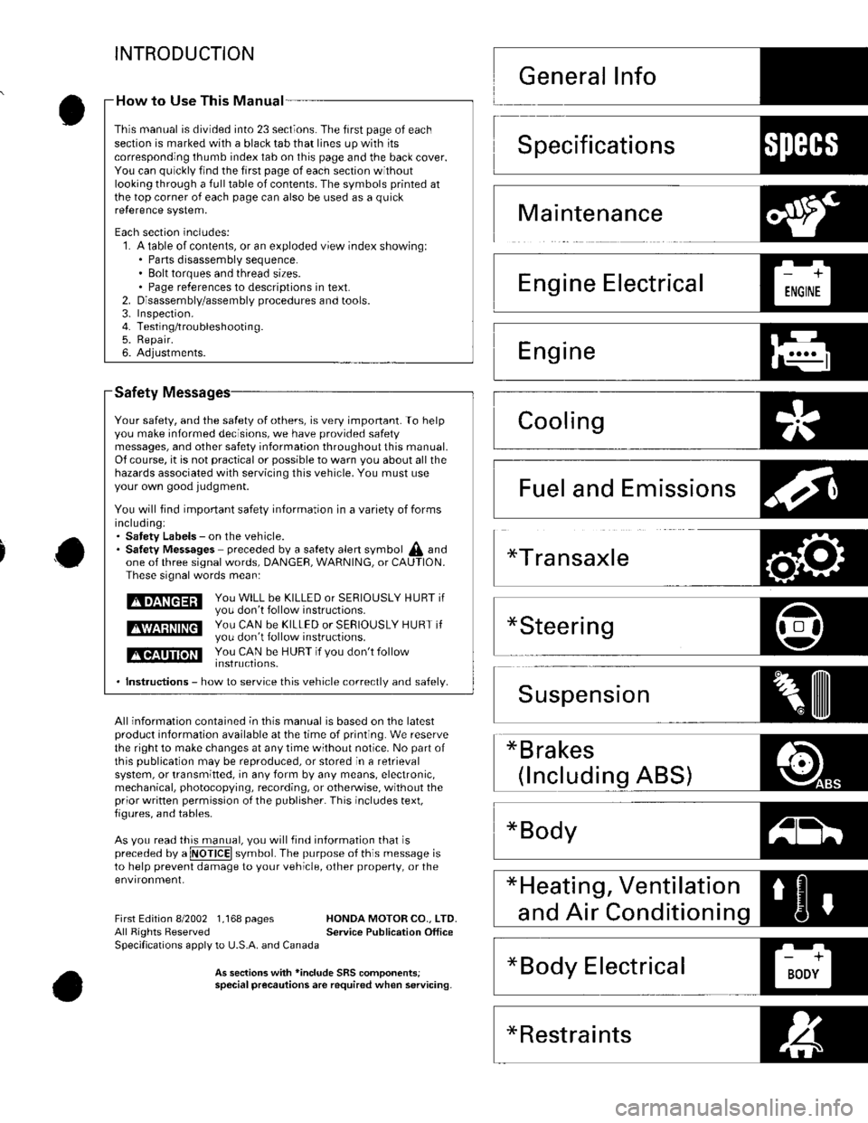
INTRODUCTION
Safety
Your safety, and the satety of others, is very important. To helpyou make informed decisions, we have provided safetymessages, and other safety information throughout this manual.Of course, it is not practical or possible to warn you about all thehazards associated with servicing this vehicle. You must useyour own good judgment.
You will find impoftant safety information in a variety of formsincluding:. Satety Labels - on the vehicle.. Satetv Messages preceded by a salety alert symbol A andone of three signal words, DANGEF, WARNING, or CAUTION.These signal words mean:
tmEnEEril y;,: H,ll i": 5* i5"?;r s E R I o u s LY H u Br ir
E$EEEE ys,: f#,ff ,:hl:3,:JjERrousLY HURT ir
tlGtltT]llilll You cAN b€ HUBT if vou don't follow
. lnstructions - how to service this vehicle correctlv and safelv.
All information contained in this manual is based on the latestproduct information available at the time of printing. We reservethe right to make changes at any time without notice. No part ofthis Oublication maV be reDrodLrced, or stored in a retrievalsystem, or transmitted, in any form by any means, electronic,mechanical, photocopying, recording, or otherwise, without theprior written permission o{ the publisher. This includes text,figures, and tables-
As vou read this manual, vou will tind information that ispreceded by a @ symbol. The purpose of this message isto help prevent damage to your vehicle, other property, or theenvironment,
*Bodyz-tl!^t l
First Edition 8/2002 1,168 pages HONDA MOTOR CO.. LTD.All Rights Reserved Service Publication OfficeSpecifications apply to U.S.A. and Canada
As seclion3 with *inclode SRS comoonentsispecial precautionsare required when servicing.
How to Use This Manual -
This manual is divided into 23 sections. The first page of eachseclion is marked with a black tab that lines up with itscorresponding thumb index tab on this page and the back cover.You can quickly find the first page of each section withoutlooking through a full table of contents. The symbols printed atthe top corner of each page can also be used as a quickre{erence system.
Each section includes:1. A table of contents, or an exploded view index showingl. Parts disassembly sequence.. Bolt torques and thread sizes.. Page references to descriptions in text.Disassembly/assembly procedures and tools.Inspefiron.Testing/troubleshootin g.Repair.Adjustments.
2.3.4.5.6.
Specifications1)ll:{l+'
Maintenance
Emissions
*Restraints
Page 4 of 1139
General Information
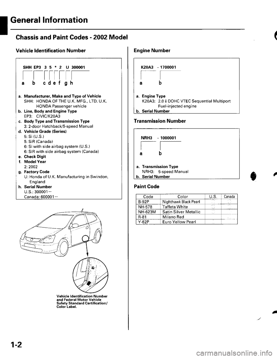
Chassis and Paint Codes - 2OO2 Model
Vehicle ldentffi cation Number
SHHEP3 35'2 U 300001
[[tttrtF
cdef gh
a. Manufacturer, Make and Type of Vehicle
SHH; HONDAOFTHE U.K. MFG., LTD. U.K.
HONDA Passenger vehicle
b. Line, Body and Engine Type
EP3: CIVIC/K20A3
c. Body Type and Transmission Type
3: 2-door HatchbacUs-speed Manual
d. Vehicle Grade lSeries)
5: Si {U.S.}
5; SiR (Canada)
6: Si with side airbag system (U,S.)
6: SiR with side airbag system (Canada)
e. Check Digit
l. ModelYear
2i 2002
g. Factory Code
U: Honda of U.K. Manufacturing in Swindon,
E ng land
h. Serial Number
U.S,: 300001 -
1-
V€hicle ldentif ication Numbo.and Federal Motor VehicleSaf ety Standard Certif ication/Color Label.
1-2
I
1700001K2OA3
a
a. Engine Type
K20A3: 2.0 0 DOHC VTEC Sequential Multiport
Fuel-injected engine
b. Serial Number
Engine Number
Transmission Number
Paint Code
CodeColoru.s.Canada
B-92PNiqhthawk Black Pearl
NH-578Taffeta White
NH-623MSatin Silver lvletallic
R-81Milano Red
Y-62PEuro Yeliow Pearl
NBH3
I
a
Transmission Type
NRH3; s-sDeed Manual
1000001
t0
Page 5 of 1139
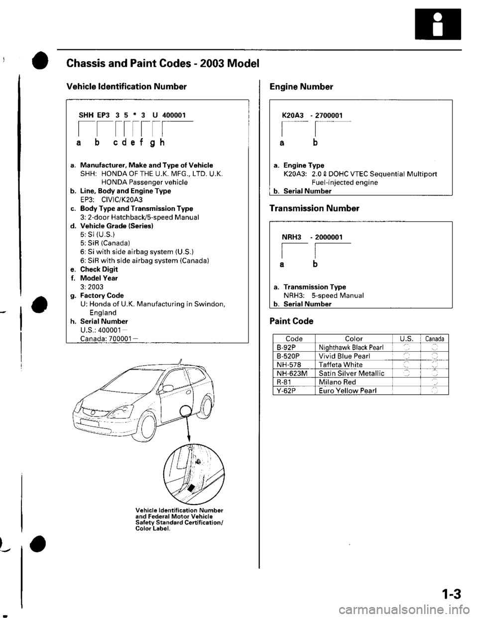
Chassis and Paint Codes - 2003 Model
Vehicle ldentif ication Number
SHHEP3 35*3 U 400001
[--t-rlF
cdef gh
G.
d.
Manufacturer, Make and Type of Vehicle
SHH: HONDAOFTHE U.K. MFG., LTD. U.K.
HONDA Passenger vehicle
Line. Body and Engine Type
EP3: CIVIC/K20A3
Body Type and Transmission Type
3: 2-door HatchbacldS-speed Manual
Vehicle Grade (Series)
5: Si (U.S.)
5: SiR (Canada)
6: Si with side airbag system (U.S.)
6: SiR with side airbag system (Canada)
Check Digir
Model Year
3: 2003
Factory Code
U: Honda of U.K. Manufacturing in Swindon,
England
Serial Number
U.S.: 400001
f.
:700001
Vehicle ldentification Numberand Federal Motor VehicleSaletv Standard Certif ication/Color Label.
)_.
2700001K2OA3
I
a
a. Engine Type
K20A3: 2.0 0 DOHC VTEC Sequential Multiport
Fuel-injected engine
b. Serial Number
Engine Number
Transmission Number
NRH3
I
a
Transmission Type
NRH3: 5-speed Manual
Serial Number
- 2000001
Paint Code
CodeColorU,S.Canada
B-92PNiohthawk Black Pearl
B-520PVivid Blue Pearl
NH-578Taffeta White
NH-623MSatin Silver N4etallic
R-81Milano Red
Y-62PEuro Yellow Pearl
1-3
Page 24 of 1139
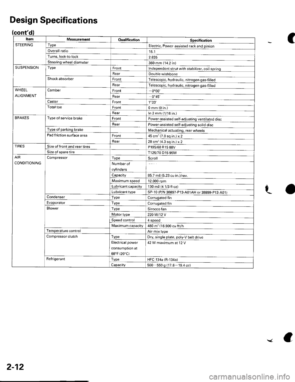
cont'
ItemMeasuremeniOualificationSpecilicationSTEERINGTypeElectric, Power assisted rack and pinion
Overall ratio15.1Turns,lock to-lock
Steering wheel diameter360 mm (14.2 in)SUSPENSIONTypeIndependent srrul with stabiliTer. coil springRearDouble wishboneShock absorberFrontTelescopic, hydraulic. nitrogen gas-frlled
RearTelescopic, hydraulic, nitrogen gas,filledWHEEL
ALIGNMENT
CamberFront0"00'
Bear0.45'�
CasterFront1'33'�TotaltoeFront0 mm (0 in.)
RearIn 2 mm (1/16 in.)BRAKESType of service brakeFrontPowerassisted self-adjusling ventilated disc
BearPower-assisted self-adjusting solid discType of parking brakeMechanical actuating, rear wheelsPad friction surface areaFront45 cm'(7.0 sq in.)x2
Rear28 cm'(4.3 sq in.) x 2TIRESSize offront and reartiresPl95/60 815 88VSize o{ spare tireT125r0 D15 95MAIR
CONDITIONING
CompressorTypeScroll
Number of
cylinders
Capacity85.7 m015.23 cu in.)/rev.
Maximum speed12,000 rpm
Lubricant capacity130 m0 {4 1/3 floz)
LubricanttypeSP-10 (P/N 38897'P13-A01AH or38899-P13 A01)CondenserTypeCorrugated finEvaporatorTvpeCorrugated fin
BlowerTypeSirocco fan
Motor type220 Wl12 V
Speed control4 Speeo
Maximum capacity480 m" 116.900 cu ft)/hTemperature controlAirmixtype
Compressor clutchTvpeDry, single plate, poly-V belt drive
Electricalpower
cons!mptron at
68"F (20.C)
42 W maximum at 12 V
RefrigerantTypeHFC 134a (R-134a)
Capacity500 550 g (17.6 19.4 oz)
Design Specifications
C
aL
2-12
../ a
Page 28 of 1139
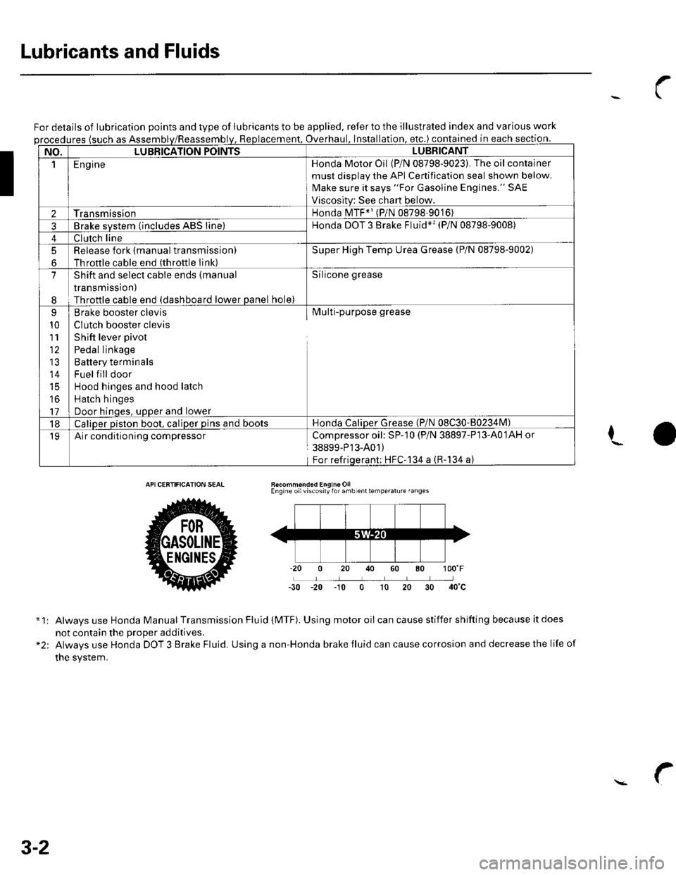
Lubricants and Fluids
For details of lubrication points and type of lubricants to be applied, refer to the illustrated index and various work
ures {such as Assemoverhaul. lnstallation. etc.) contained in each section.
NO.LUBBICATION POINTSLUBBICANT
1E ng ineHonda Motor Oil (P/N 08798-9023). The oil container
must disolav the API Cenification seal shown below.
Make sure it says "For Gasoline Engines." SAE
Viscositv: See chart below.
2TransmissionHonda MTF*' (P/N 08798-9016)
3Brake svstem (includes ABS line)Honda DOT 3 Brake Fluid*'� (P/N 08798-9008)
4Clutch line
5
6
Release fork (manual transmissionl
Throftle cable end (throttle Iink)
Super High Temp Urea Grease {P/N 08798-9002)
7
I
Shift and select cable ends (manual
transmission)
Throttle cable end (dashboard lower panel hole)
Silicone grease
9
10
111'
14
16
17
Brake booster clevis
CIutch booster clevis
Shift lever pivot
Pedal linkage
Battery terminals
Fuel f ill door
Hood hinges and hood latch
Hatch hinges
Door hinoes, uoDer and lower
Multi-purpose grease
18Caliper piston boot, caliper pins and bootsHonda CaliDer Grease (P/N 08C30-80234lvl)
19Air conditioning compressorCompressoroil: SP-10 (P/N 38897-P13-A01AH or
38899-P'13-A01)
For refriqerant; HFC'134 a (R-134 a)
I
Recommond6d Engine OilEngine oilviscosily for amb enttemperalure fanges
-30 -20 -10 0 t0 20
*1:
"2:
Always use Honda Manual Transmission Fluid (MTF). Using motor oii can cause stiffer shifting because it does
not contain the Drooer additives.
Always use Honda DOT 3 Brake Fluid. Using a non-Honda brake fluid can cause corrosion and decrease the life of
the system.
3-2
Page 43 of 1139
Starting System
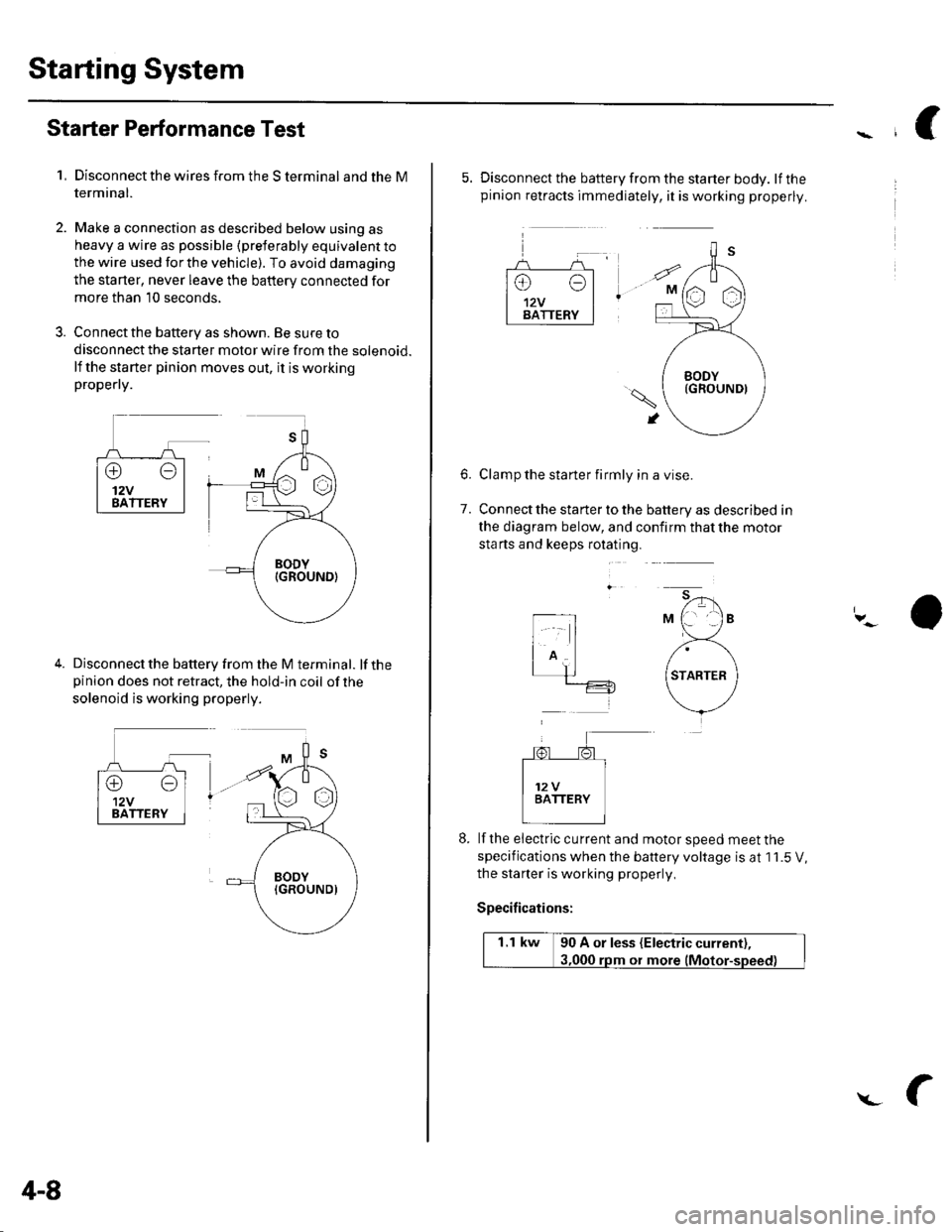
Starter Performance Test
1,Disconnect the wires from the S terminal and the M
termrnal.
Make a connection as described below using as
heavy a wire as possible (preterably equivalent to
the wire used for the vehicle). To avoid damaging
the starter, never leave the battery connected for
more than 10 seconds,
Connect the battery as shown. Be sure to
disconnect the starter motor wire from the solenoid.
lf the starter pinion moves out, it is workingpropefly.
Disconnect the battery from the M terminal. lf thepinion does not retract, the hold-in coil of the
solenoid is working properly.
4-8
L
5. Disconnect the battery from the starter body. lfthepinion retracts immediately, it is working properly.
Clamp the starter firmly in a vise.
Connect the starter to the battery as described in
the diagram below, and confirm that the motor
sta rts and keeps rotating.
6.
7.
lf the eiectric cu rrent and motor speed meet the
specifications when the battery voltage is at 1 1.5 V,
the staner is working properly,
Specifications:
1.1 kw 90 A or less (Electric current),
ot more
Page 59 of 1139
Gharging System
Charging Circuit Troubleshooting (cont'd)
6. Start the engine. Hold the engine at 3,000 rpm with
no load (in Neutral) until the radiator fan comes on,
then let it idle.
7. Raise the engine speed to 2,000 rpm, and hold it
there.
8. Turn the headlights (high beam) on, and measure
voltage at the under-hood fuse/relay box terminal.
ls the voltage between 13.9 and 15.1 v?
YES-Go to step 9.
NO Repair or replace the alternator components
(see page 4-30).1
9. Read the amperage at '13.5 V.
NOTE: Adjust the voltage by turning the blower
motor, rear window defogger, brake lights. etc. ON.
ls the amperage 604 ot morc?
YES-Alternator/regulator operation is OK. I
NO Repair or replace the alternator components(see page 4-30).1
4-24
\,
Alternator Control System Test
NOTE: After troubleshooting, perform the engine
control module (ECM) idle learn procedure (see page
11-139).
1 . Check for proper operation of the electrical load
detector (ELD) by checking the malfunction
indicator lamp (MlL) (see page 1 l-3). lf a DTC is
present, diagnose and repair the cause before
continuing with this test.
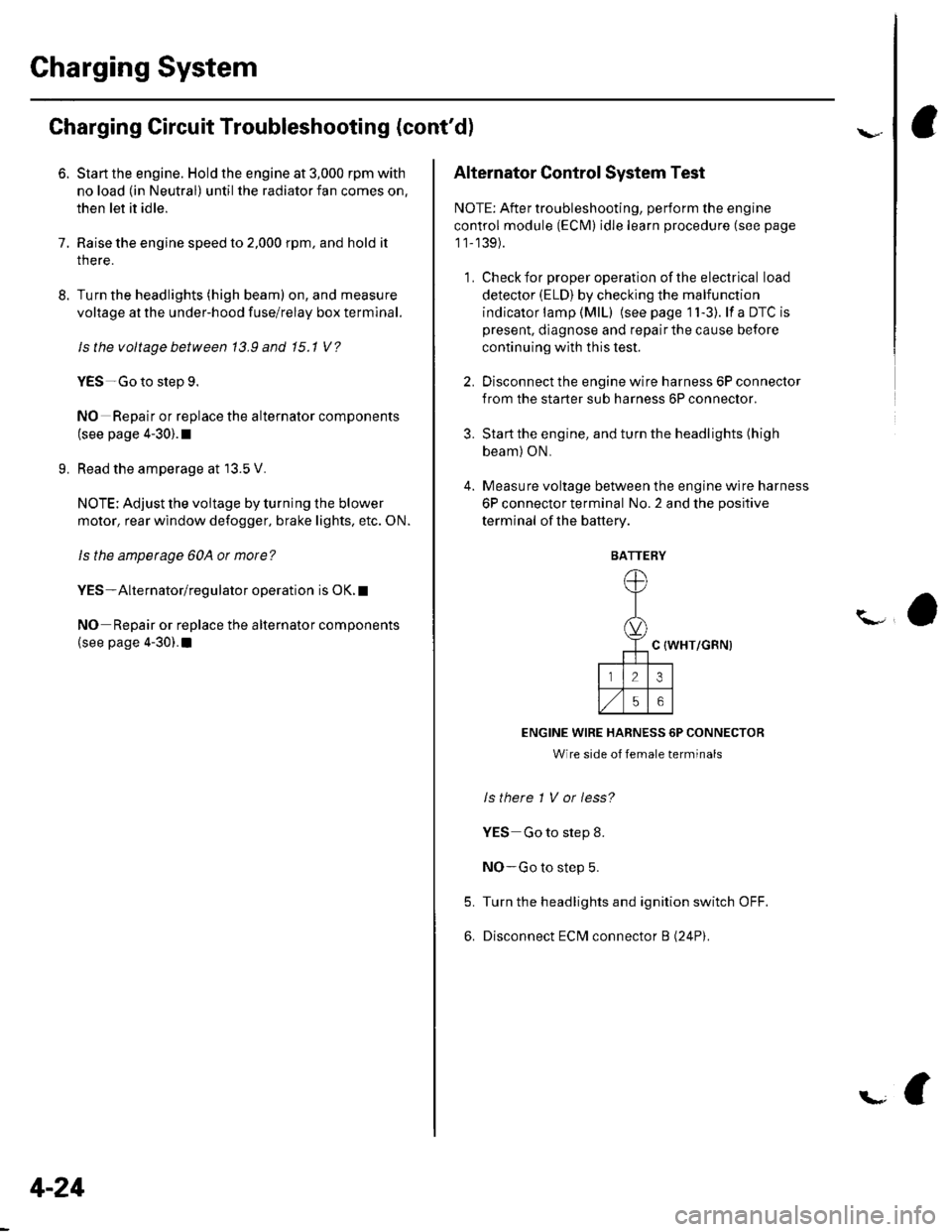
2. Disconnect the engine wire harness 6P connector
from the starter sub harness 6P connector.
3. Start the engine, and turn the headlights (high
beam) ON,
4. Measure voltage between the engine wire harness
6P connector terminal No. 2 and the positive
terminal of lhe battery.
C {WHT/GRN)
ENGINE WIRE HARNESS 6P CONNECTOR
Wire side of female terminals
ls there 1 V or less?
YES Go to step 8.
NO-Go to step 5.
Turn the headlights and ignition switch OFF.
Disconnect ECM connector B (24P).
5.
6.
BATTERY
Page 76 of 1139
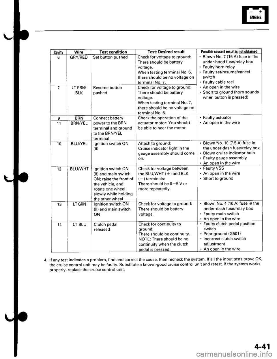
CavityWireTest conditionTest: Desired resultPossible cause il result is not obtained
6GRYiREDSet button pushedCheck for voltage to ground:
There should be battery
voltage,
When testing terminal No.6,
there should be no voltage on
terminal No. 7.
Blown No.7 (15 A)fuse in the
under-hood fuse/relay box
Faulty horn relay
Faulty sevresume/cancel
swrtch
Faulty cable reel
An open in the wire
Shon to ground (horn sounds
when button is pressed)
7LT GRN/
BLK
Resume button
pusneo
Check for voltage to ground:
There should be battery
voltage.
When testing terminal No.7,
there should be no voltage on
terminal No. 6.
BRNConnect battery
power to the BRN
terminal and ground
to the BRNIVEL
termrnal
Check the operation of the
actuator motor: You should
be able to hear the motor.
. Faulty actuator. An open in the wire11BRNI/EL
10B LUIVE Llgnition switch ON
0r)
Attach to groundi
Cruise indicator light in the
gauge assembly should come
on.
Blown No. 10 (7.5 A) fuse in
the under-dash fuse/relay box
Blown cruise indicator bulfl
Faulty gauge assembly
An open in the wire
12BLU/VVHTlgnition switch ON
(ll) and main switch
ON; raise the front of
the vehicle, and
rotate one wheel
slowly while holding
the other wheel
Check for voltage between
thE BLU/VVHT (+) ANd BLK
( )terminals:
Thereshouldbe0 5Vor
more repeatedly.
Faulty VSS
An open in the wire
Short to ground
13LT GRNlgnition switch oN
{ll) and main switch
ON
Check for voltage to ground:
There should be battery
voltage.
Blown No. 4 (10 A)fuse in the
under-dash fuse/relay box
Faulty main switch
An oDen in the wire
14LT BLUClutch pedal
reteaseo
Check for continuity to
grouno:
There should be continuity.
NOTE:There should be no
continuity when the clutch
oedal is Dressed.
Faulty clutch pedal position
swtlcn
Poor ground (G501)
Incorrect clutch switch
adjustment
An open in the wire
lf any test indicates a problem, find and correct the cause, then recheck the system. lf all the input tests prove OK,
the cruise control unit may be faulty. Substitute a known-good cruise control unit and retest. lf the system works
properly, replace the cruise control unit.
4-41
Page 78 of 1139
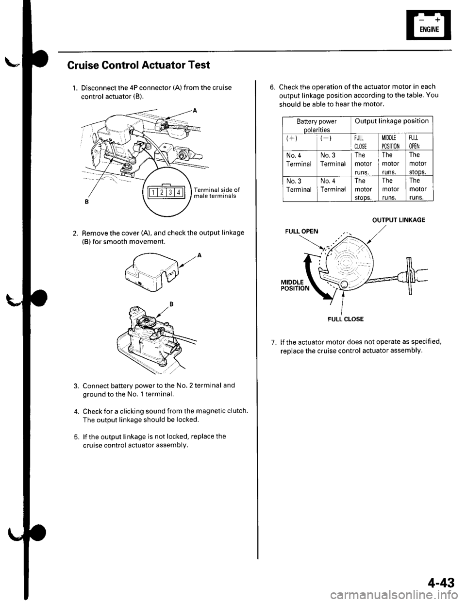
Cruise Control Actuator Test
1. Disconnect the 4P connector (A) from the cruise
control actuator (B).
Remove the cover (A), and check the output linkage
(B) for smooth movement.
2.
,to
5.
Connect battery power to the No, 2 terminal and
ground to the No. 1 terminal.
Check for a clicking sound from the magnetic clutch.
The output linkage should be locked.
lf the output linkage is not locked, replace the
cruise control actuator assembly,
6. Check the operation of the actuator motor in each
output linkage position according to the table. You
should be able to hear the motor.
Battery power
Dolarities
Output linkage position
FULt
CLOSE
MIDDLE
PO$TION
FUtL
OPEN
No,4
Terminal
No.3
Terminal
The
motor
runs.
The
motor
runs.
The
motor
stoDs,
No.3
Terminal
No. 4
Terminal
The
motor
sIoos.
The
motor
runs.
The
motor
runs.
1.lf the actuator motor does not operate as specified,
replace the cruise control actuator assembly,
OUTPUT LINKAGE
FULL CLOSE
4-43
Page 101 of 1139
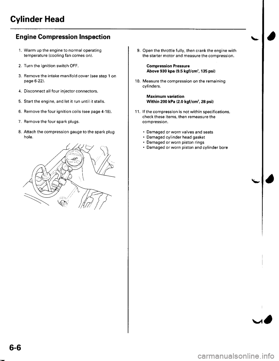
Cylinder Head
Engine Compression Inspection
1. Warm up the engine to normal operating
temperature (cooling fan comes on).
2. Turn the ignition switch OFF.
3. Remove the intake manifold cover (see step 1 onpage 6-22).
4, Disconnect all four injector connectors.
5. Start the engine, and let it run until it stalls.
6. Remove the iour ignition coils (see page 4-18).
7. Remove the four spark plugs.
8. Attach the compression gauge to the spark plug
note.
6-6
V,
\
9.
10.
Open the throttle fully, then crank the engine with
the starter motor and measure the compression.
Compression Pressure
Above 930 kpa (9.5 kgf/cm', 135 psi)
Measure the compression on the remaining
cylinders,
Maximum vadation
Within 200 kPa (2.0 kgf/cm', 28 psi)
lf the compression is not within specifications,
check these items, then remeasure the
compressron.
. Damaged orworn valves and seats. Damaged cylinder head gasket. Damaged or worn piston rings. Damaged orworn piston and cylinder bore
11.
\-