Mount bracket HONDA CIVIC 2002 7.G Workshop Manual
[x] Cancel search | Manufacturer: HONDA, Model Year: 2002, Model line: CIVIC, Model: HONDA CIVIC 2002 7.GPages: 1139, PDF Size: 28.19 MB
Page 84 of 1139
Engine Assembly
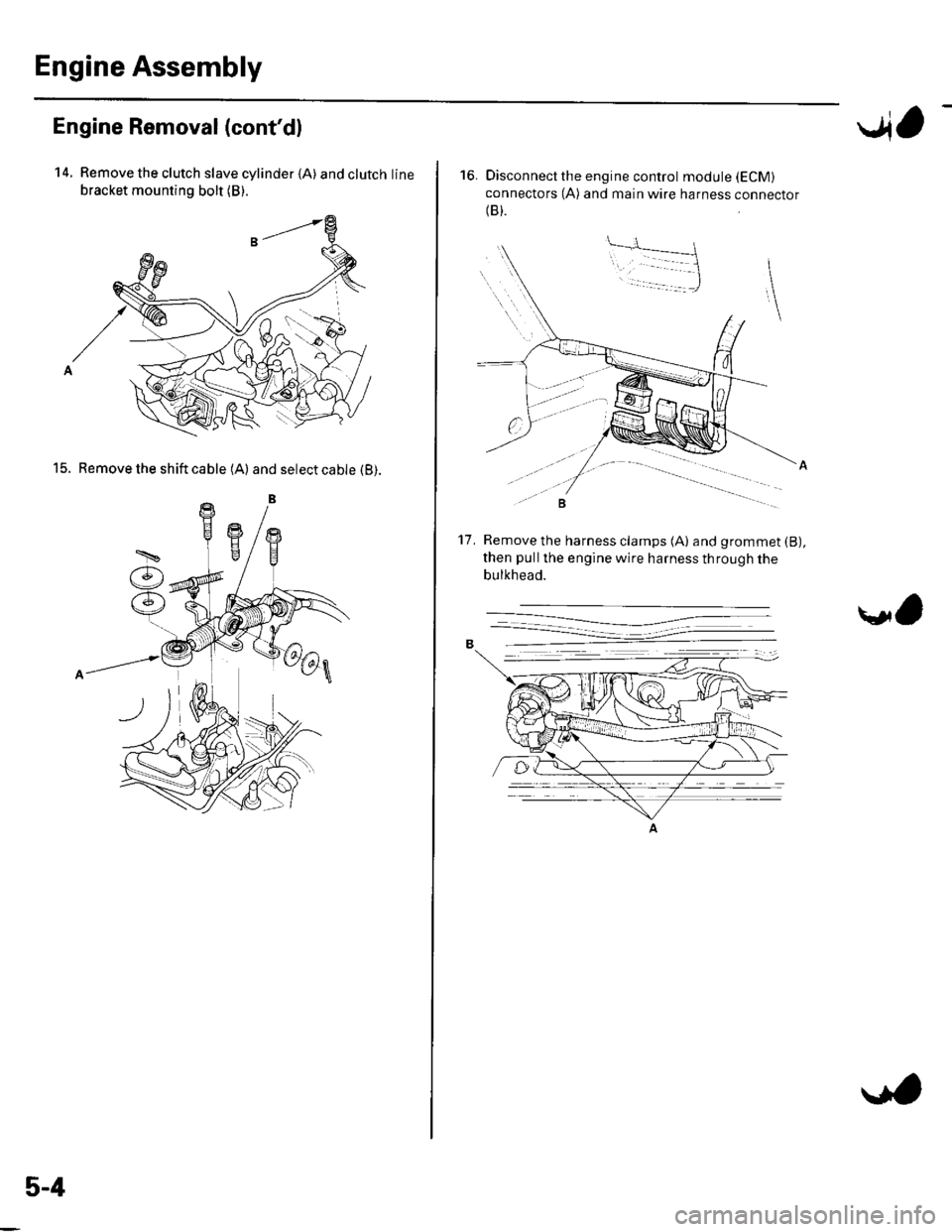
Engine Removal (cont'dl
14. Remove the clutch slave cylinder {A) andclutchline
bracket mounting bolt (B).
15. Remove the shift cable (A) and select cable (B).
5-4
..4,
16. Disconnect the engine control module (ECM)
connectors (A) and main wire harness connector(B).
Remove the harness clamps (A) and grommet (B),
then pullthe engine wire harness through the
bulkhead.
't7 .
\l,
Page 86 of 1139
Engine Assembly
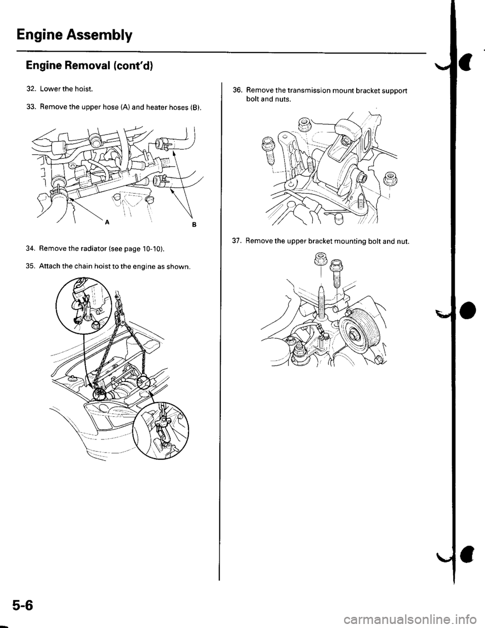
Engine Removal (cont'd)
32. Lower the hoist.
33. Remove the upper hose (A)and heater hoses (B).
34. Bemove the radiator (see page 10-10).
35. Attach the chain hoist to the engine as shown.
5-6
36. Remove the transmission mount bracket support
bolt and nuts.
37. Remove the upper bracket mounting bolt and nut.
(.g
\a
Page 87 of 1139
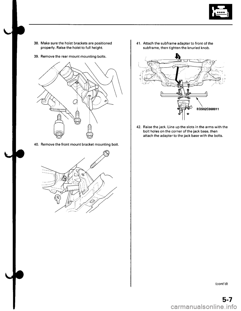
39.
Make sure the hoist brackets are positioned
properly. Raise the hoist to full height.
Remove the rear mount mounting bolts.
40. Remove the front mount bracket mountinq bolt.
41. Attach the subframe adapterto front ofthe
subframe, then tighten the knurled knob.
Raise the jack. Line up the slots in the arms with the
bolt holes on the corner of the jack base, then
attach the adaDter to the iack base with the bolts.
(cont'd)
5-7
Page 89 of 1139
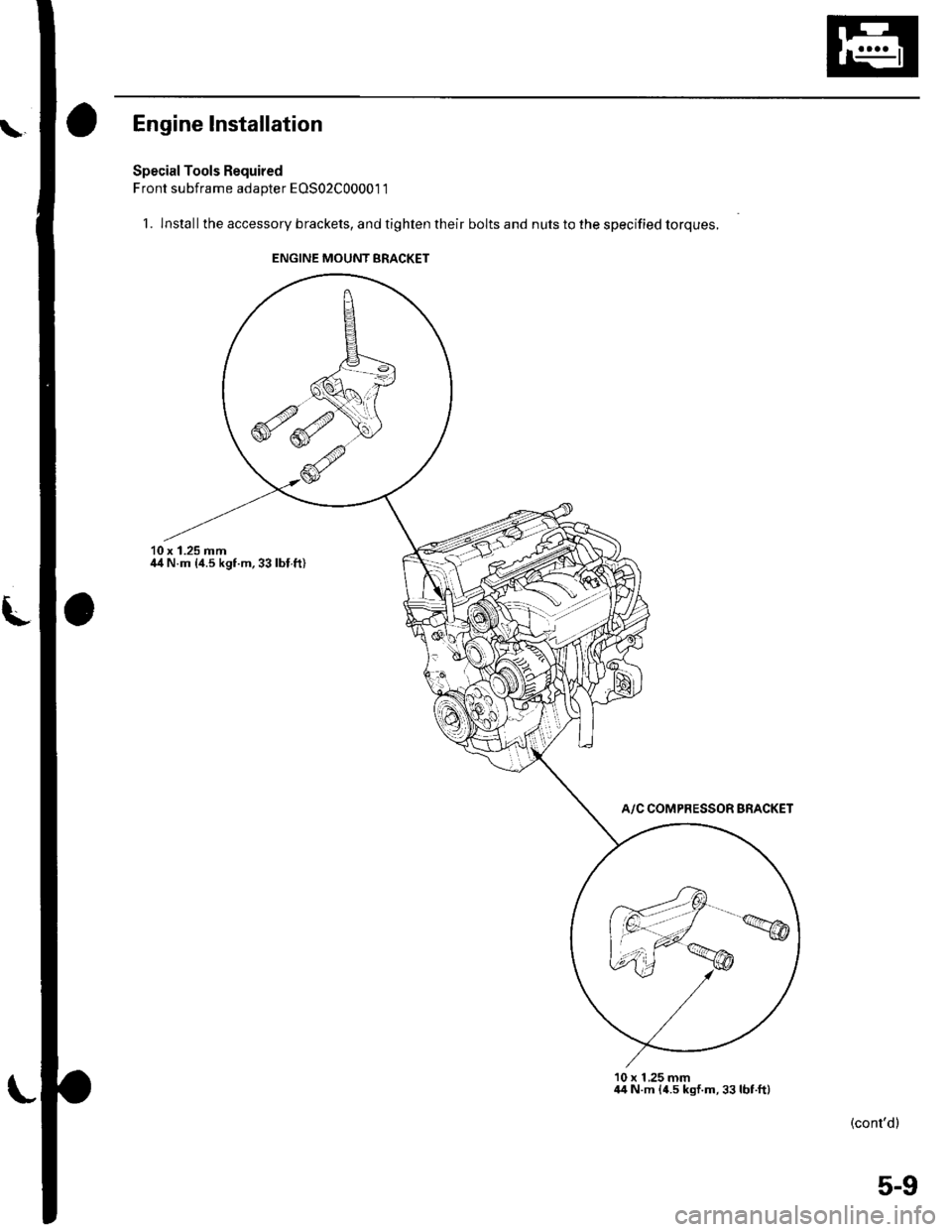
Engine lnstallation
Special Tools Required
Front subframe adapter EOS02C00001 1
1. lnstallthe accessory brackets, and tighten their bolts and nuts to the specified torques.
10 x 1.25 mmil4 N.m {4.5 kgf.m,33lbl.ft)
A/C COMPRESSOR BRACKET
10 x 1 ,25 mm44 N.m {4.5 kgf.m,33lbt.ft)
(cont'dl
ENGINE MOUNT BRACKET
5-9
Page 91 of 1139
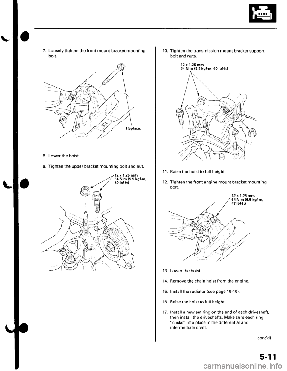
7. Loosely tighten the front mount bracket mounting
bolt.
Lower the hoist.
Tighten the upper bracket mounting bolt and nut.
8.
9.
10. Tighten the transmission mount bracket support
bolt and nuts.
12 x 1.25 mm54 N m {5.5 kgt m, 40 lbf.ft}
Raise the hoist to full height.
Tighten the front engine mount bracket mounting
bolt.
'l '1.
't2.
12 x 1.25 rnrn64 N.m {6.5 kgf.m,47 tbt.ftl
13. Lower the hoist.
14. Remove the chain hoist from the engine.
'15. Installthe radiator (see page 10-10).
'16. Raise the hoist to full height.
17. Install a new set ring on the end of each driveshaft,
then install the driveshafts. Make sure each ring"clicks" into place in the differential and
intermediate shaft.
(cont'd)
:l
5-11
Page 94 of 1139
Engine Assembly
Engine Installation {cont'dl
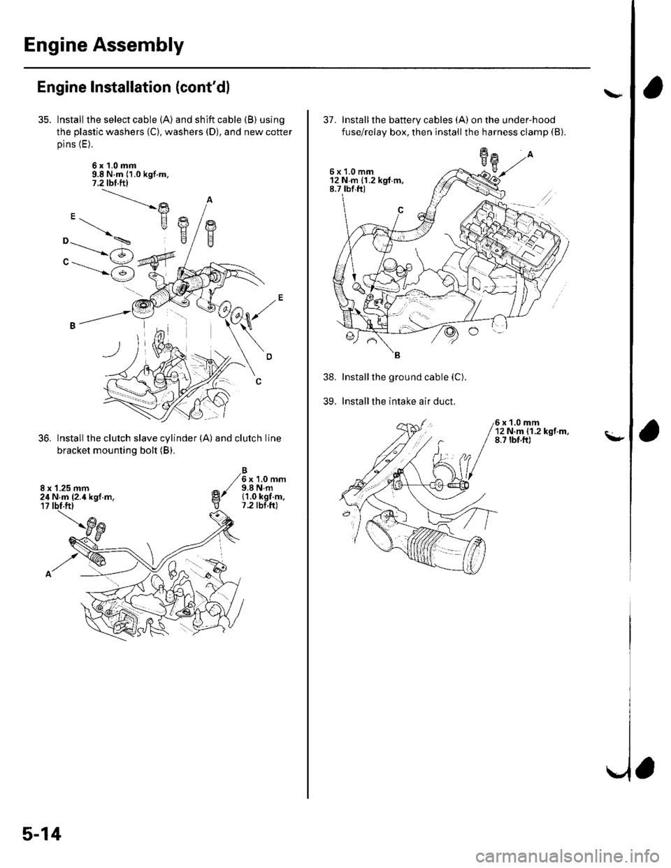
Install the select cable (A) and shift cable (B) using
the plastic washers (C), washers (D), and new cotter
pins (E).
6x1.0mm9.8 N.m (1.0 kgf.m,7.2 tbl.ftl
Install the clutch slave cylinder (A) and clutch line
bracket mounting bolt (B).
6x1.0mm9.8 N.m{1.0 kgf.m,7.2 tbt.ft)
"-.----->)
"------'6
8 x '1.25 mm24 N.m (2.4 kgl.m,
5-14
37. Installthe battery cables (A) on the under-hood
fuse/relay box, then install the harness clamp (B).
Installthe ground cable (C).
Installthe intake air duct.
6x1.0mm12Nm{1.2kgf.m,8.7 tbf.ft)
39.
\"
\-
a
6x1.0mm12Nm{1.2kgt.m,8.7 rbf.ft)
Page 108 of 1139
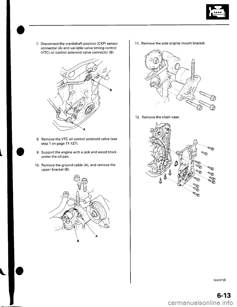
7. Disconnectthe crankshaft position (CKP) sensor
connector {A) and variable valve timing control
{VTC) oil control solenoid valve connector (B).
Remove the VTC oil control solenoid valve (see
step 1 on page 11-127).
Support the engine with a iack and wood block
under the oil pan.
Remove the ground cable (A). and remove the
upper bracket (B).
9.
10.
11. Remove the side engine mount bracket.
12. Remove the chain case.
(cont'd)
6-13
Page 113 of 1139
Gylinder Head
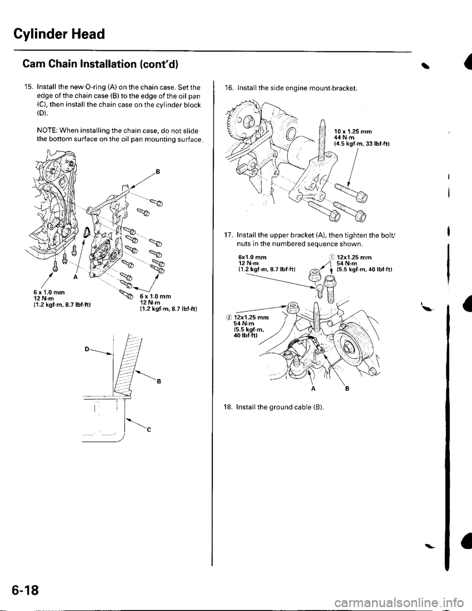
Cam Chain Installation (cont'd)
'15. Install the new O-ring (A) on the chain case. Set the
edge of the chain case (B) to the edge of the oil pan(C), then install the chain case on the cvlinder block(D).
NOTE: When installing the chain case, do not slide
the bottom surface on the oil pan mounting surface.
',.9
6x1.0mm12 N.m(1.2 kgt.m.8.7 lbf.ft)
6x1.0mm12Nm(1.2 kgf.m,8.7 lbf.ft)
6-18
\-
{t
16. lnstallthe side engine mount.bracket.
17. Installthe upper bracket (A), then tighten the bolv
nuts in the numbered seouence shown.
6x1.0 mm12 N.m{1.2 kgl m, 8.7 lbf ft}
12x1.25 mm54 N.m(5.5 kgt m, 40 lbf.ft)
I\a
18. Install the ground cable (B).
rbf.ft)
Page 118 of 1139
Gylinder Head Removal
NOTE:. Use fender covers to avoid damaging painted
surfaces.
To avoid damage, unplug the wiring connectors
carefully whlle holding the connector portion.
To avoid damaging the cylinder head, wait until the
engine coolant temperature drops below 100'F (38"C)
betore loosening the cylinder head bolts.
Mark all wiring and hoses to avoid misconnection.
Also, be sure that they do not contact other wiring or
hoses, or interfere with other parts.
'1.
2.
3.
Drain the engine coolant (see page 10-6).
Remove the drive belt (see page 4-26).
Remove the intake manifold {see page 9-3).
Remove the air cleaner housing (see step 7 on page
5-2t.
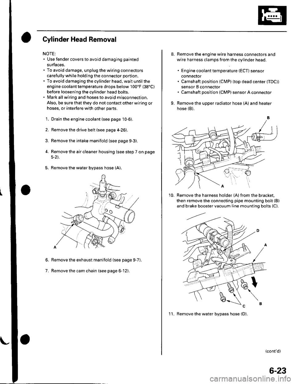
5. Remove the water bypass hose (A).
Remove the exhaust manifold (see page 9-7
Remove the cam chain (see page 6-12).
6.
7.
).
8. Remove the engine wire harness connectors and
wire harness clamps from the cylinder head.
. Engine coolant temperature (ECT) sensor
conneclor. Camshaft position (Cl\4P) (top dead center (TDC))
sensor B connector. Camshaft posilion (CMP) sensor A connector
9. Remove the upper radiator hose (A) and heater
hose (B).
'10. Remove the harness holder (A)from the bracket,
then remove the connecting pipe mounting boh {B)
and brake booster vacuum line mounting bolts {C).
(cont'd)
1 1. Remove the water bvpass hose (D).
6-23
Page 135 of 1139
Cylinder Head
8.
Cylinder Head lnstallation (cont'd)
7.Apply engine oil to the bolt threads and under thebolt heads of all the cylinder head bolts.
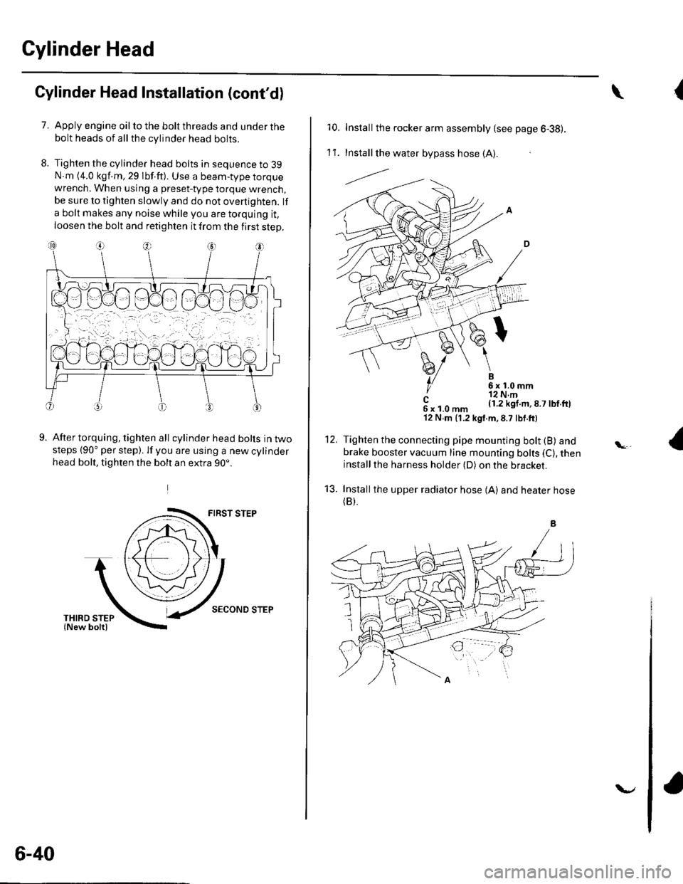
Tighten the cylinder head bolts in sequence to 39N.m {4.0 kgf.m, 29 lbf.ft). Use a beam-type torquewrench. When using a preset-type torque wrench,be sure to tighten slowly and do not overtighten. lf
a bolt makes any noise while you are torquing it,
loosen the bolt and retighten it from the first step.
9.After torquing, tighten all cylinder head bolts in twosteps (90" per step). lf you are using a new cylinderhead bolt, tighten the bolt an extra 90..
FIRST STEP
SECOND STEP
6-40
v
{\
10. Installthe rocker arm assembly {see page 6-38).
1't .Install the water bypass hose (A).
---l.-.
B6x1.0mm'r2 N.m(1.2 kgl.m,8.7 lbf.ftl
12.
't3.
c6xl.0mm'12 N,m (1.2 kgt.m,8.7 lbf.ft)
Tighten the connecting pipe mounting bolt (B) andbrake booster vacuum line mounting bolts (C), theninstallthe harness holder (D) on the bracket.
Installthe upper radiator hose {A) and heater hose(B).