automatic HONDA CIVIC 2002 7.G Workshop Manual
[x] Cancel search | Manufacturer: HONDA, Model Year: 2002, Model line: CIVIC, Model: HONDA CIVIC 2002 7.GPages: 1139, PDF Size: 28.19 MB
Page 509 of 1139
EPS Components
aGeneral Troubleshooting Information
EPS Indicator
Under normal conditions, the EPS indicator comes on when
the ignitlon switch is turned to the ON (ll) position, then goes
off after the engine is started. This indicates that the bulb and
its circuit are operating correctly.
lf there is any trouble in the system after the engine is started,
the EPS indicator will stay on, and the power assist is turned
off.
When EPS indicator light comes on, the control unit
memorizes the DTC. In this case, the control unit will not
activate the EPS system after the engine starts again, but it
keeps the EPS indicator on.
When DTC 12, 16, 17, 18 or 67 is stored in the control unit, the
EPS indicator will stay on until the DTC is erased. When a
problem is detected and the EPS indicator comes on, there are
cases when the indicator stays on untilthe ignition switch is
turned 0FF, and cases when the indicator goes off
automatically when the system returns to normal. Even though
the system is operating normally, the EPS indicator will come
on under the following conditions:
Condition '1:
. The vehicle was traveling at least 12.4 mph (20 km/h), then. A rapid change in vehicle speed was detected, then. The vehicle (or the vehicle speed sensor signal) stopped for
at least 5 seconds. The engine speed was still 'l,640rpmorhigherforatleastS
seconds
Condition 2:
After the vehicle (or the vehicle speed sensor signal) has
stopped for at least 10 seconds, yet the engine speed was still
1,640 rpm or higherfor at least 20 seconds.
Condition 3:
When the engine speed is 280 rpm or less, and the vehicle is traveling at
a speed of 6,2 mph (10 km/h) or more for 3 seconds.
To determine the actual cause ofthe problem, question the
customer about the conditions during which the problem
occured, taking the above conditions into consideration.
Diagnostic Trouble Code (DTCI
. lf the CPU cannot be activated, or itfails,the EPS indicator
comes on, but the DTC is not memorized.. The memory can hold any number of DTCS. However, when
the same DTC is detected more than once, the most recent
DTC is written over the prior DTC, therefore only one
occurrence is memorized.. The DTCS are indicated repeatedly untilthe ignition switch is
turned OFF.. lf the DTC is not memorized,the EPS indicator blinks.
. The DTCS are memorized in the EEPRO| (non-volatile
memory) therefore the memorized DTCS cannot be erased
by disconnecting the battery. Perform the specified
procedures to clear DTCS.
Self-diagnosis
Self-diagnosis can be classified into two categories:.Initial diagnosis: performed right after the engine
starts and until the EPS indicator goes off.. Regular diagnosis: performed right after the initial
diagnosis until the ignition switch is turned OFF.
The EPS control unit performs the following functions
when a problem is detected by self-diagnosis;
'1. Turns on the EPS indicator.
2. Memorizes the DTC.
3. Stops power assist and manual steering operation
begrns.
NOTE:. When DTC 23 (a problem with the circuit for
engine speed signal) is detected, the power
assist will return to normal when the vehicle
speed is 0.62 mph (1 km/h) or above.. Fot DfCs 22,23, 64, or 66 the EPS indicator goes
off automatically when the system relurns to
normal. For all other codes, the EPS indicator
goes off when the system is OK after the ignition
switch is turned from OFF to ON (ll).
Restriction on Power Assist Operation
Repeated extreme steering force. such as turning the
steering wheel continuously back-and-forth with the
vehicle stopped, causes an increase of power
consumption in the EPS motor. The increase of electric
current causes the motor to heat up. Because this heat
adversely affects the system, the control unit monitors
the electric current of the motor.
When the control unit detects heat build-up in the motor,
it reduces the electric current to the motor gradually to
protect the system, and it restricts the power assist
operation. The EPS indicator does not come on during
this function.
When steering torque is not applied to the steering
wheel, or when the ignition is turned off, and the motor
cools, the control unit will restore the power assist
gradually until it's fully restored (after approximately 15
minutes maximum).
17-18
Page 601 of 1139
Conventional Brake Components
Brake Pedaland Brake PedalPosition Switch Adjustment
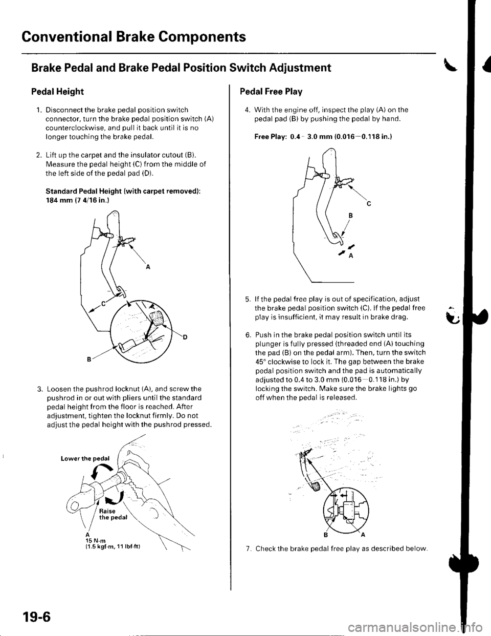
Pedal Height
1.Disconnect the brake pedal position switch
connector, turn the brake pedal position switch (A)
counterclockwise, and pull it back until it is no
longer touching the brake pedal.
Lift up the carpet and the insulator cutout (B).
l\4easure the pedal height (C) from the middle of
the left side of the pedal pad (D).
Standard Pedal Height (with carpet removed):
184 mm (7 4/16 in.)
Loosen the pushrod locknut (A), and screw the
pushrod in or out with pliers until the standard
pedal height from the floor is reached. After
adjustment, tighten the locknut firmly. Do not
adjust the pedal height with the pushrod pressed.
15 N.m(1.5 kgl m. 11 lbl ft)
19-6
7. Check the brake pedal free play as described below.
Pedal Free Play
4. With the engine off, inspect the play (A) on the
pedal pad (B) by pushing the pedal by hand.
Free Play: 0.4- 3.0 mm {0.016 0.'l18in.)
lf the pedal free play is out of specification, adjust
the brake pedal position switch (C). lf the pedal free
play is insufficient, it may result in brake drag.
Push in the brake oedal oosition switch until its
plunger is fully pressed (threaded end (A)touching
the pad (B) on the pedal arm). Then, turn the switch
45" clockwise to lock it. The gap between the brake
pedal position switch and the pad is automatically
adjusted to 0.4 to 3.0 mm (0.016 0.118 in.) by
locking the switch. Make sure the brake lights go
otf when the pedal is released.
t
6.
Page 625 of 1139
General Troubleshooting Information
ABS Indicator
. lf the system is OK,theABS indicator goes off 2
seconds after turning the ignition switch ON (ll)
without starting the engine, and then comes on again
and goes off 2 seconds later after starting the engine.
This occurs because the ABS control unitisturned
on by the lG2 power source.. The ABS indicator comes on when the ABS control
unit detects a problem in the system. However, even
though the system is operating properly, the indicator
will come on under these conditions:- Only the drive wheels rotate- One drive wheel is stuck- The vehicle goes into a spin- The ABS continues to operate for a long time.- The vehicle is subjected to an electrical signal
disturbance
To determine the actual cause of the problem, question
the customer about the problem. taking the above
condilions into consideration.
. When a Droblem is detected and lhe ABS indicator
comes on, there are cases when the indicator stays
on until the ignition switch is turned OFF, and cases
when the indicator goes off automatically when the
sYstem returns to normal.- DTC 61: The ABS indicator goes off automatically
when the system returns to normal.- DTC 11, 13,15,17 ,31,32,33, 34, 35, 36, 37, 38, 54,
or 81: The ABS indicator stays on until the ignition
switch is turned OFF whether or not the system
returns to normal.- DfC 12, 14, 16, 1a,21,51,52, or 53; The ABS
indicator goes off when the vehicle is driven again
and the system is OK after the ignition switch is
turned from OFF to ON {ll}.
Diagnostic Trouble Code {DTCI
. The memory can hold three DTCS. However, when
the same DTC is detected more than once, the more
recent DTC is written over the earlier one.
Therefore, when the same problem is detected
repeatedly, it is memorized as a single DTC.. The DTCs are in the order they occurred, beginning
with the most recent.. The DTCS are memorized in the EEPROM (non-
volatile memory). Therefore. the memorized DTCs
are not cleared when the battery is disconnected, the
ignition switch is turned off, or the system returns to
normal. Do the specified procedures to clear the
DTCs.
Self-diagnosis
. Self-diagnosis can be classified into two categories:- Initial diagnosis:
Done right after the engine starts and until the ABS
indicator goes off- Regular diagnosis:
Done rightafterthe initial diagnosis until the
ignition switch is turned OFF. When a problem is detected by self-diagnosis, the
system does the following:- Turns the ABS indicator on- Memorizes the DTC- Stops ABS control
Kickback
The pump motor operates when the ABS is functioning,
and the fluid in the reservoir is forced out to the master
cylinder, causing kickback at the brake pedal.
Pump Motor
. The pump motor operates when the ABS is
functioning.. The ABS control unit checks the pump motor
operation when the vehicle is started the first time
after the ignition switch is turned ON (ll). You may
hear the motor operate at this time, but it is normal.
(cont'd)
19-31
Page 992 of 1139
Transmitter Test
NOTE:. lf the doors unlockorlockwiththetransmitter, but
the LED on the transmitter does not come on, the LED
is faulty. Replace the transmitter,. lf anydoor isopen, you cannotlockthedoorwiththe
transmrtter.. lf you unlocked the doors with the transmitter, but do
not open any of the doors within 30 seconds, the
doors relock automatically.. The doors do not lock or unlock with the transmitter if
the ignition key is inserted in the ignition switch.
1. Press the lock or unlock button five or six times to
reset the transmitter.
. lf the locks work, the transmitter is OK.. lf the locks don't work, go to step 2.
2. Open the transmitter and check for water damage.
. lf you find any water damage, replace the
transmrtter.. lf there is no waterdamage, go to step 3.
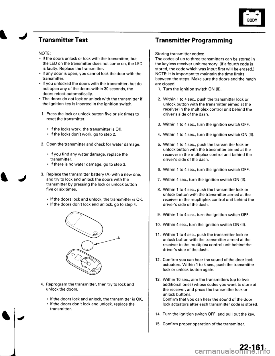
3. Replace the transmitter battery (A) with a new one,
and try to lock and unlock the doors with the
transmitter by pressing the lock or unlock button
five or six times.
. lf the doors lock and unlock, the transmifter is OK.. lf the doors don't lock and unlock, go to step 4.
Reprogram the transmitter, then try to lock and
unlock the doors.
. lf thedoors lockand unlock.thetransmitter is OK.. lf the doors don'tlockand unlock, replacethe
transmitter.
4.
Transmitter Programming
Storing transmitter codes:
The codes of up to three transmitters can be stored in
the keyless receiver unit memory. (lf a fourth code is
stored. the code which was input first will be erased.)
NOTE: lt is important to maintain the time limits
between the steps. Make sure the doors and the hatch
are closed.
1. Turn the ignition switch ON (lli.
2. Within 1 to 4 sec., push the transmitter lock or
unlock button with the transmitter aimed at the
receiver in the multiplex control unit behind the
driver's side of the dash.
3. Within 1 to 4 sec., turn the ignition switch OFF.
4. Within 1 to 4 sec., turn the ignition switch ON (ll).
5. Within 'l to 4 sec., push the transmitter lock or
unlock button with the transmitter aimed at the
receiver in the multiplex control unit behind the
driver's side of the dash.
6. Within 1 to 4 sec., turn the ignition switch OFF.
7. Within 4 sec., turn the ignition switch ON (ll).
8. Within 1 to 4 sec., push the transmitter lock or
unlock button with the transmifter aimed at the
receiver in the mupltiplex control unit behind the
driver's side of the dash.
9. Within 1 to 4 sec., turn the ignition switch OFF,
'10. Within 4 sec., turn the ignition switch ON (ll).
11. Within 1 to 4 sec., push the transmitter lock or
unlock button with the transmitter aimed at the
receiver in the multiplex control unit behind the
driver's side of the dash.
12. Confirm you can hearthe sound ofthe door lock
actuators. Within 1 to 4 sec., push the transmitter
lock or unlock button again,
13, Within 10 sec., aim the transmitters (up to two
additional ones) whose codes you want to store at
the receiver, and press the transmitter lock or
unlock buttons.
Confirm that you can hear the sound of the door
lock actuators after each transmitter code is stored.
14. Turn the ignition switch OFF, and pull out the key.
'15. Confirm proper operation ofthe transmitter.
22-161
Page 1018 of 1139
Seat Belts
Inspection (cont'd)
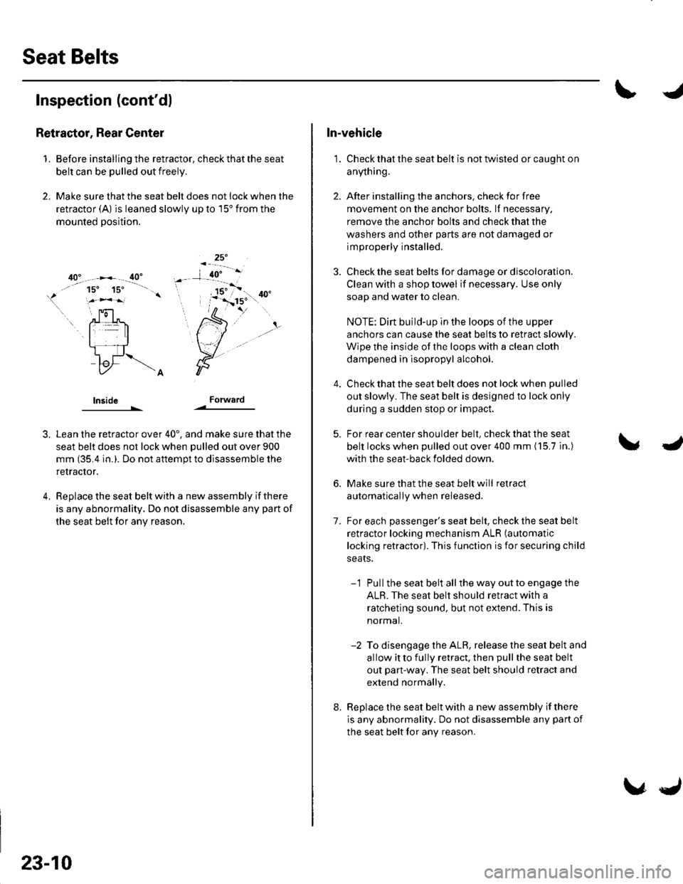
RetraEtor, Rear Center
1. Before installing the retractor, check that the seat
belt can be pulled out freely.
2, Make sure that the seat belt does not lock when the
retractor (A) is leaned slowly up to 15' from the
mounted position.
lnsideForward
3,
4.
Lean the retractor over 40', and make sure that the
seat belt does not lock when pulled out over 900
mm (35.4 in.). Do not aftempt to disassemble the
retractor.
Replace the seat belt with a new assembly if there
is any abnormality. Do not disassemble any part of
the seat belt for any reason.
23-10
\,J
In-vehicle
1. Check that the seat belt is not twisted or caught on
anything.
2. After installing the anchors. check for free
movement on the anchor bolts. lf necessary,
remove the anchor bolts and check that the
washers and other parts are not damaged or
improperly installed.
3. Check the seat belts for damage or discoloration.
Clean with a shop towel if necessary. Use only
soap and water to clean.
NOTE: Dirt build-up in the loops of the upper
anchors can cause the seat belts to retract slowly.
Wipe the inside of the loops with a clean cloth
dampened in lsopropyl alcohol.
Check that the seat belt does not lock when pulled
out slowly. The seat belt is designed to lock only
during a sudden stop or impact.
For rear center shoulder belt, check that the seat
belt locks when pulled out over 400 mm (15.7 in.)
with the seat-back folded down.
Make sure that the seat belt will retract
automatically when released.
For each passenger's seat belt, check the seat belt
retractor locking mechanism ALR (automatic
locking retractor). This function is for securing child
seats.
-1 Pullthe seat belt allthe way outto engage the
ALR. The seat belt should retract with a
ratcheting sound, but not extend. This is
normal.
-2 To disengage the ALR, release the seat belt and
allow itto fully retract, then pullthe seat belt
out part-way. The seat belt should retract and
extend normally.
Replace the seat belt with a new assembly if there
is any abnormality. Do not disassemble any part of
the seat belt for any reason.
7.
8.
Page 1038 of 1139
ISystem Description
SRS Components
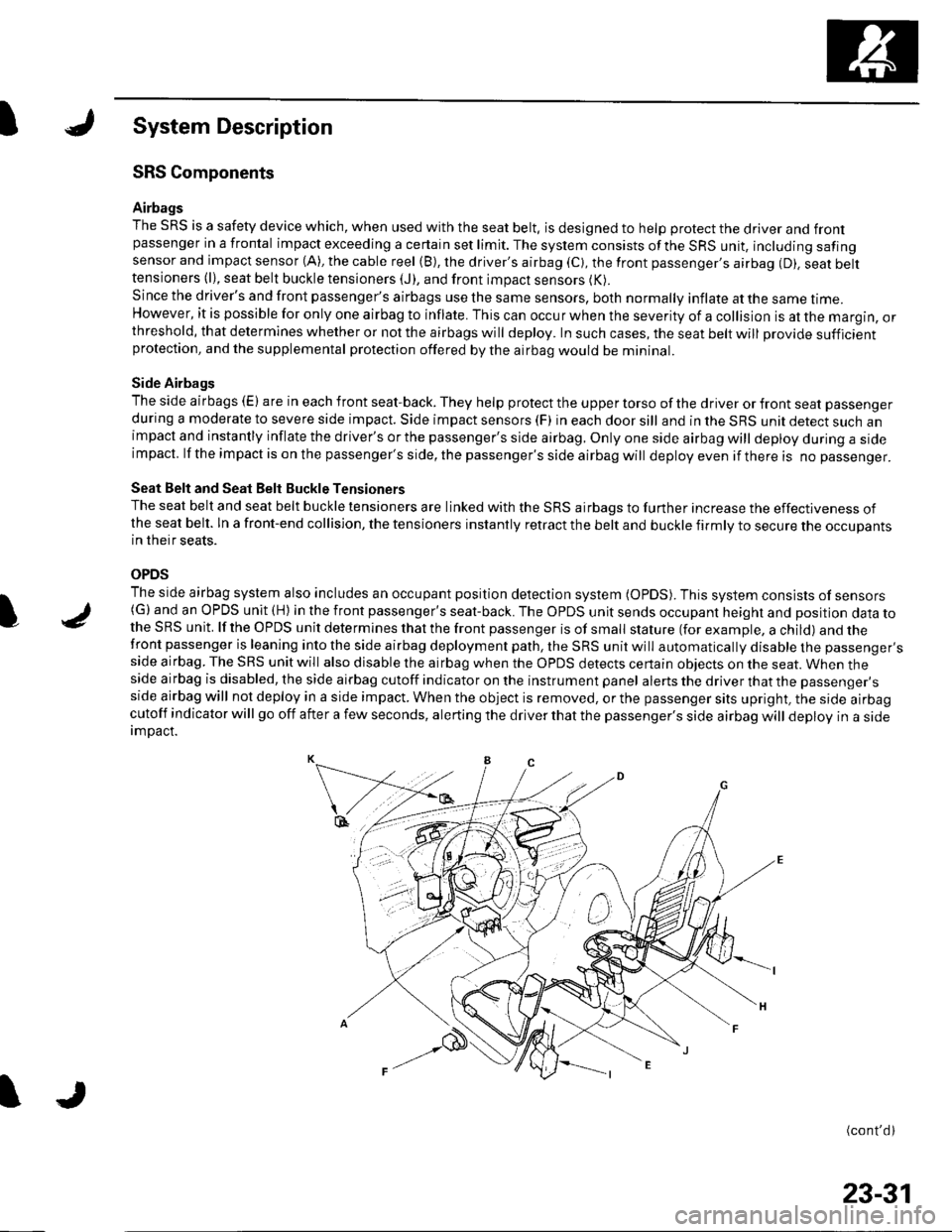
Airbags
The SRS is a safety device which, when used with the seat belt, is designed to help protect the driver and frontpassenger in a frontal impact exceeding a certain set limit. The system consists ofthe SRS unit, including safingsensor and impact sensor (A), the cable reel (B), the driver's airbag (C), the front passenger,s airbag (D). seat belttensioners (l), seat belt buckle tensioners (J), and front impact sensors (K).
Since the driver's and front passenger's airbags use the same sensors, both normally inflate at the same ttme.However, it is possible for only one airbag to inflate. This can occur when the severity of a collision is at the margin, orthreshold, that determines whether or not the airbags will deploy. In such cases, the seat belt will provide sufficientprotection, and the supplemental protection offered by the airbag would be mininal.
Side Airbags
The side airbags (E) are in each front seat-back. They help protect the upper torso of the driver or front seat passenger
during a moderate to severe side impact. Side impact sensors (F) in each door sill and in the SRS unit detect such animpact and instantly inflate the driver's or the passenger's side airbag. Only one side airbag will deploy during a sideimpacl. lf the impact is on the passenger's side, the passenger's side airbag will deploy even if there is no passenger.
Seat Belt and Seat Belt Buckle Tensioners
The seat belt and seat belt buckle tensioners are linked with the SRS airbags to further increase the effectiveness ofthe seat belt. ln a front-end collision, the tensioners instantly retract the belt and buckle firmly to secure the occupantsin their seats.
OPDS
The side airbag system also includes an occupant position detection system (OpDS). This system consists of sensors(G)and an OPDS unit (H) in the front passenger's seat-back. The OPDS unit sends occupant heighl and position data tothe SRS unit. lf the OPDS unit determines that the front passenger is of small stature (for example, a child) and thefront passenger is leaning into the side airbag deployment path, the SRS unit will automatically disable the passenger'sside airbag. The SRS unit will also disable the airbag when the OPDS detects certain obiects on the seat. When theside airbag is disabled, the side airbag cutoff indicator on the instrument panel alerts the driver that the passenger'sside airbag will not deploy in a side impact. When the object is removed, or the passenger sits upright, the side airbagcutoff indicator will go off after a few seconds, alerting the driver that the passenger's side airbag will deploy in a sideimDact.
(cont'd)
I
23-31