head HONDA CIVIC 2002 7.G Workshop Manual
[x] Cancel search | Manufacturer: HONDA, Model Year: 2002, Model line: CIVIC, Model: HONDA CIVIC 2002 7.GPages: 1139, PDF Size: 28.19 MB
Page 15 of 1139
L
vlo
2-3
a
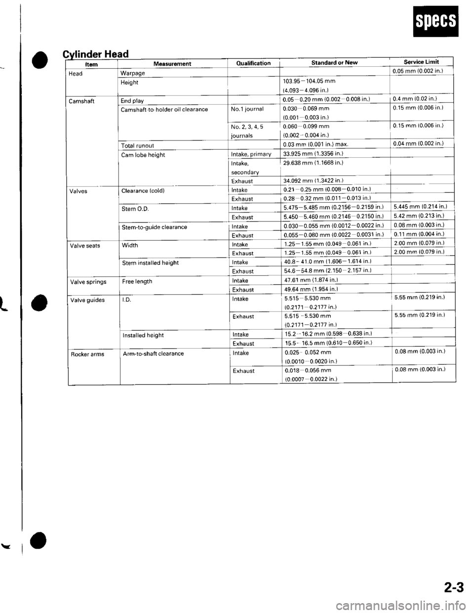
ead
o
nder H
ItemMeasur6mentOualificationStandard or NewService Limit
HeadWarpage0.05 mm {0.002 in.)
Height'103.95 104.05 mm
(4.093 4.096 in.)
CamshaftEnd play0.05 0.20 mm (0.002 0.008 in.)0.4 mm (0.02 in.)
Camshaft to holder oil clearanceNo.l journal0.030 0.069 mm
{0.001 0.003 in.)
0.15 mm {0.006 in.)
No.2,3, 4,5
journals
0.060 0.099 mm
(0.002- 0.004 in.)
0.15 mm (0.006 in.)
Total runout0.03 mrn (0.001 in.) max.0.04 mm {0.002 in.)
Cam lobe heightIntake, primary33.925 mm (1.3356 in.)
Intake,29.638 mm (l.1668 in.)
Exhaust34.092 mm (1.3422 in.)
clearance (cold)lntake0.21 0.2s mm 10.008 0.010 in.)
Exhaust0.28 0.32 mm (0.011 0.013 in.)
Stem O.D-lnlaKe5.475 5.485 mm 10.2156 0.2159 in.)5.445 mm (0.214 in.)
Exhaust5.450 5.460 mm (0.2146 0.2150 in )5.42 mm (0.213 in.)
Stem-to-gLride clearancelntake0.030 0.055 mm (0.0012 0.0022in.|0.08 mm (0.003 in.)
Exhaust0.055 0.080 mm (0.0022 0.0031 in )0.11 mm (0.004 in.)
lntake1.25 1.55 mm (0.049 0.061 in.)2.00 mm {0.079 in.)
Exhaust1.25 1.55 mm (0.049 0.061 in.)2.00 mm {0.079 in.)
stem installed heightlntake40.8- 41.0 mm (1.606 1.614in.)
Exhaust54.6 54.8 mm (2.150 2.157 in.)
Valve springsFree lengthlntake47.61 mm (1.874 in.)
Exhaust49.64 mm (1.954 in.)
Valve guidesLD.Intake5.515 5.530 mm
|.0.2171 0.2117 4n.1
5.55 mm (0.219 in.)
Exhaust5.515 5.530 mm
\0.2111 0.2177 in.l
5.55 mm {0.219 in.)
Installed heightlntaKe15.2 "16.2 mm (0.598 0.638in.)
Exhaust15.5 16.5 mm (0.610 0.650 in.)
Rocker armsArm-to-shaft clearancelntaKe0.025 0.052 mm
(0.00'10 0.0020 in.)
0.08 mm (0.003 in.)
Exhaust0.018 0.056 mm
(0.0007 0.0022 in.)
0.08 mm (0.003 in.)
Page 18 of 1139
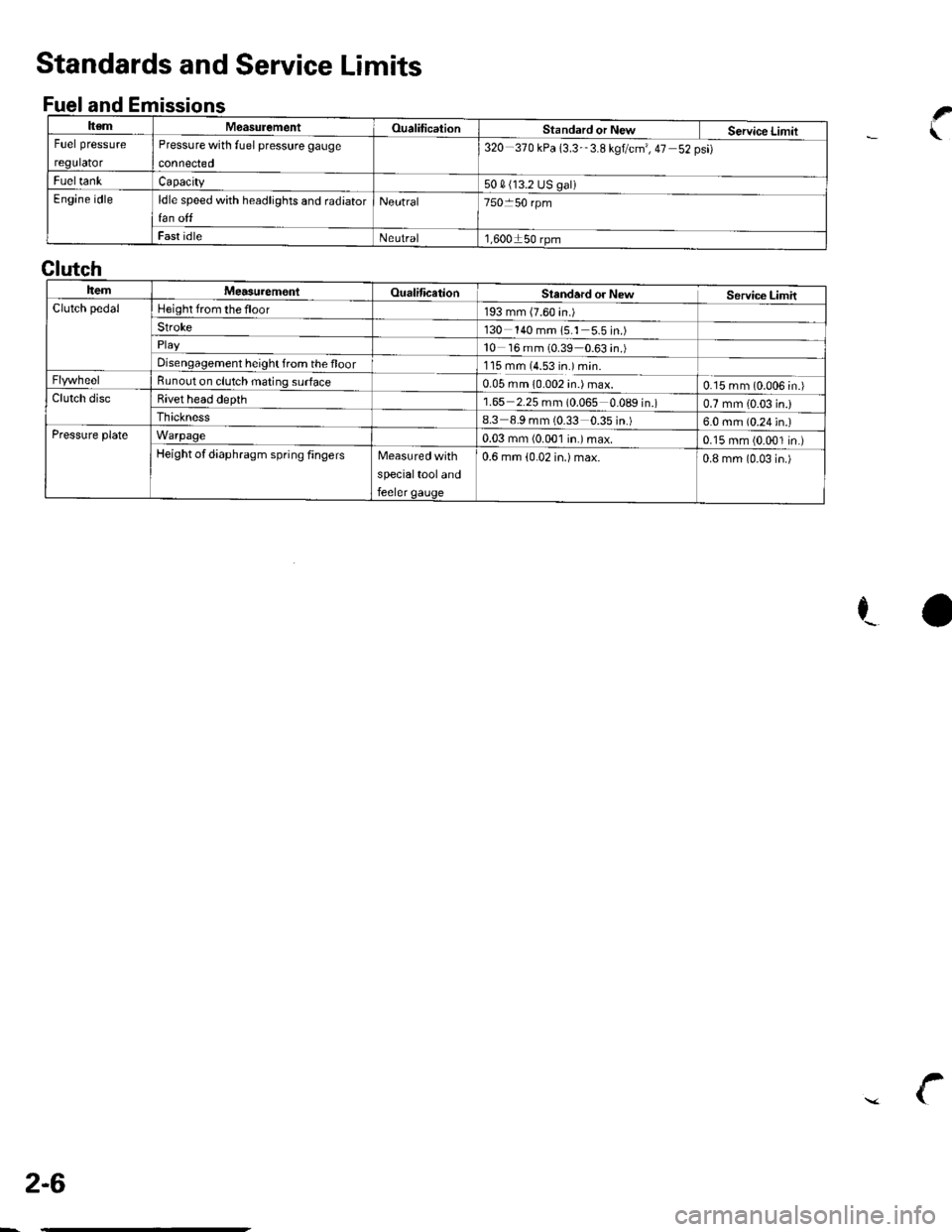
ItemMeasulementOualificationStandard or New Service LimitFuel pressure
regulator
Pressure with fuel pressure gauge
connected
320-370 kPa 13.3-'3.8 kgtcm', 47 52psi)
FueltankCapacity50 4 (13.2 US galiEngine idleldle speed with headlights and radiator
fan off
Neutral750 50 rpm
Fast idleNeutral1,600150 rpm
Standards and Service Limits
Fuel and Emissionsf
.\
ra
Clutch
ItemMea3urem€nlOualificationSlandard or NewService LimitClutch pedalHeight from the floor193 mm (7.60 in.)Stroke130 140 mm 15.1 5.5in.)
10 16 mm (0.39 0.63 in.)Disengagement height from the floor1'15 mm (4.53 in.) min.Bunout on clutch mating surface0.05 mm 10.002 in.) max.0.15 mm (0.006 in.)Clutch discBivet head depth1.65 2.25 mm (0.065 0.089 in.)0.7 mm {0.03 in.)Ihickness8.3 8.9 mm (0.33 0.35 in.)6.0 mm (0.24 in.)Pressure plateWarpage0.03 mm (0.001 in.)max.0.15 mm (0.001 in.)Height of diaphragm spring fingersMeasured with
specialtool and
feeler gauge
0.6 mm (0.02 in.) max.0.8 mm (0-03 in.)
2-6
\
Page 25 of 1139
t
v
2-13
o
o
a
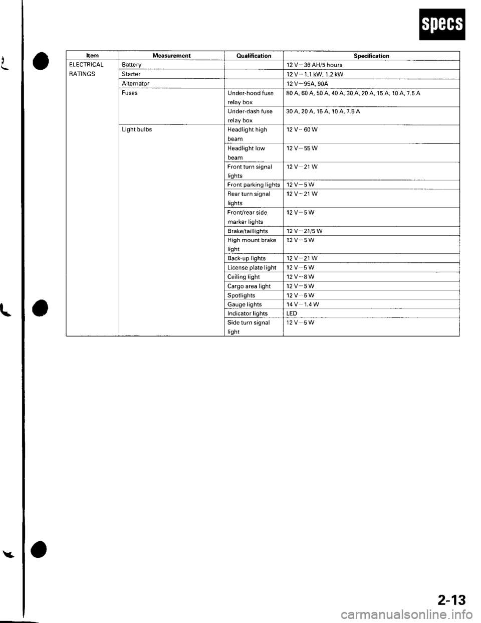
ItemMeasurementOualilicationSpecitication
ELECTRICAL
RATINGS
Battery12V 36 AH/5 hours
Sta rter12 V-.1.1 kW, 1.2 kW
Alternator12V 95A,90A
FusesUnder-hood fuse80 A, 60 A, 50 A, 40 A, 30 A, 20 A, 15 A, 10 A, 7.5 A
Under'dash Iuse30 4,20 a, 15 A, 10 A,7.5 A
Light bulbsHeadlight high
beam
'12 v.' 60 w
Headlight low
beam
12V 55W
Frontturn signal
liqhts
12V 21W
Front parlinq lights12V 5W
Bear turn signal
lights
12V " 21W
FronVrear side
marker lights
12V 5W
Brale/taillighls12V 21/5W
High moLrnt brake
light
12V 5W
Back up lights12V 21W
License plate light12V 5W
Ceiling light'12 v'.8 w
Cargo area light12V 5W
Spotlights12V 5W
Gauge lights
Indicator lightsLED
Side turn signal
light
12V 5W
Page 33 of 1139
L
A
I
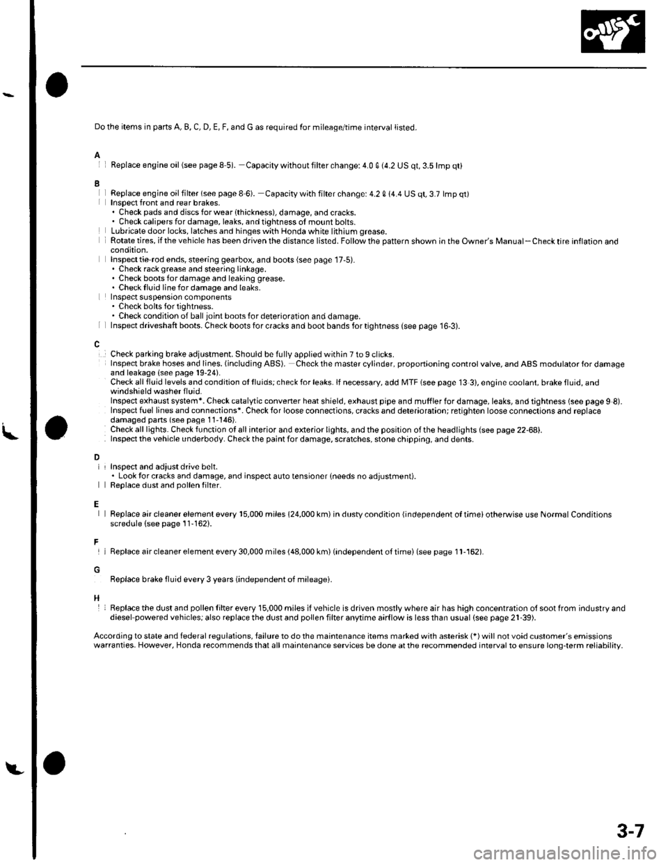
Do the items in parts A, B, C, D, E, F, and G as required for mileage/time interval listed.
Feplace engine oil(see pageS 5). Capacity withoutlilter change:4.0 q (4.2 US qt,3.5lmp qt)
Replace engjne oil filter (see page I 6). Capacity with filter change: 4.2 0 14.4 US qt, 3.7 lmp qt)Insoect front and rear brakes,. Check pads and discsforwearlthickness), damage, andcracks.. Check calipers for damage, leaks, and tightness of mount bolts.Lubricate door locks, latches and hinges with Honda white lithium grease.Rotate tires, if the vehicle has been driven the distance listed. Follow the pattern shown in the Owner's Manual-Check tire inflaron aoocondition,Inspecttie rod ends, steering gearbox, and boots (see page 17,5).. Check rack grease and steering linkage.. Check boots for damage and leaking grease.. Checklluid linefordamage and leaks.Inspect suspensron components. Check bolts for tightness.. Check condition of ball joint boots for deterioration and damage.Inspect driveshaft boots. Check boots for cracks and boot bands for tightness (see page 16-3).
Check parking brake adjustment. Should be fully applied within 7 to 9 clicks.Insp€ct brake hoses and lioes. (including ABS). Check the master cylinder, proportioning control valve, and ABS modulator for damageand leakage (see page 19-24).Check all fluid levels and condition ot lluids; check for leaks. lf necessary, add MTF (see page 13 3), engine coolant, brake fluid, andwindshield washer f luid.Inspect exhaust system*. Check catalytic converter heat shield, exhaust pipe and muffler for damage, leaks, and tightness (see page 9 8).Inspect fuel lines and connections*. Check for loose connections, cracks and deterioration; retighten loose connections and replacedamaged pans (seo page 11'146).Check alllights. Checkfunction otallinterior and exterior lights, andthe position ofthe headlights (see page 22-68).Inspect the v€hicle underbody. Check the paint for damage, scratches, stone chippin0, and dents.
L
D
E
F
H
InsDect and adiust drive belt.. Look tor cracks and damage, and inspect auto tensioner {needs no adjustment).Reolace dust and oollen filter.
Replace air cleaner element every 15,000 miles 124,000 km) in dustv condition {independent ol timei otherwise use Normal Conditionsscredule (see page 11-162).
lReplaceaircleanerelementevery30,000miles(48,000km)(independento{timei(seepagell-162).
Replace brake fluid every 3 years (independent oJ mileagei.
Replacethe dust and pollen Iilter every 15,000 miles ifvehicle is driven mostlywhere air has high concentration olsootfrom industryanddiesel powered vehiclesj also replace the dust and pollen filter anytime aarflow is less than ussal (see pags 21-39).
According to state and federal regulations, failure to do the maintenance items marked with asterisk (*) will not void customer's emissionswarranties. However, Honda recommends that all maintenance services be done at the recommended interval to ensure long-term reliability,
3-7
Page 52 of 1139
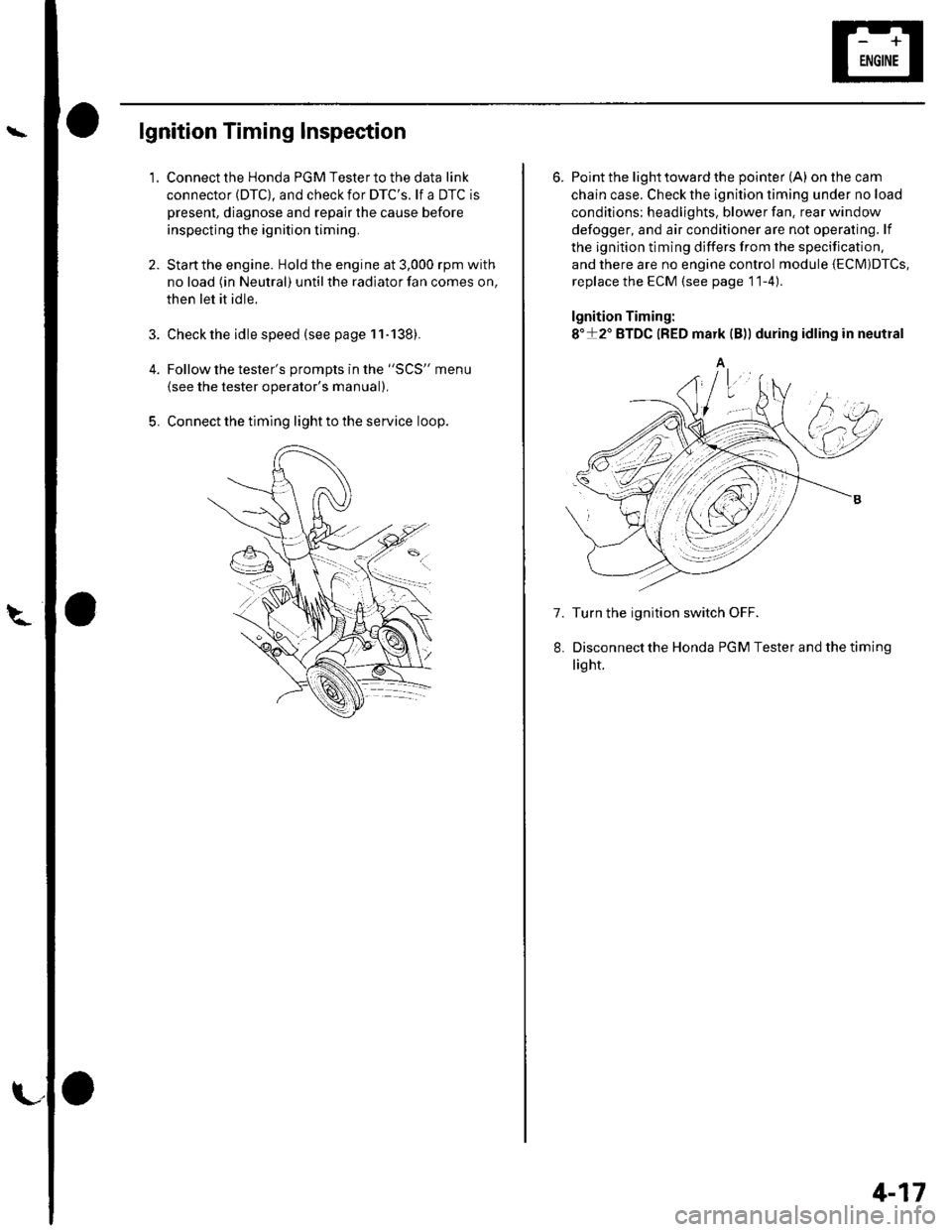
lgnition Timing Inspection
1.
4.
5.
Connect the Honda PGM Tester to the data link
connector (DTC), and check for DTC'S. lf a DTC is
present, diagnose and repair the cause before
inspecting the ignition timing.
Startthe engine. Hold the engine at 3,000 rpm with
no load (in Neutral) until the radiator fan comes on,
then let it idle.
Check the idle speed (see page 11-138).
Follow the tester's prompts in the "SCS" menu
{see the tester operator's manual),
Connect the timing light to the service loop.
o
6. Point the light toward the pointer (A) on the cam
chain case. Check the ignition timing under no load
conditions: headlights, blower fan. rear window
defogger, and air conditioner are not operaling. lf
the ignition timing differs from the specification,
and there are no engine control module {ECM)DTcs,
replace the ECM (see page 11-4)
lgnition Timing:
8"+2" BTDC {RED mark {B)) during idling in neutral
A
7. Turn the ignition switch OFF.
Disconnectthe Honda PGM Tester and thetiming
light.
4-17
Page 54 of 1139
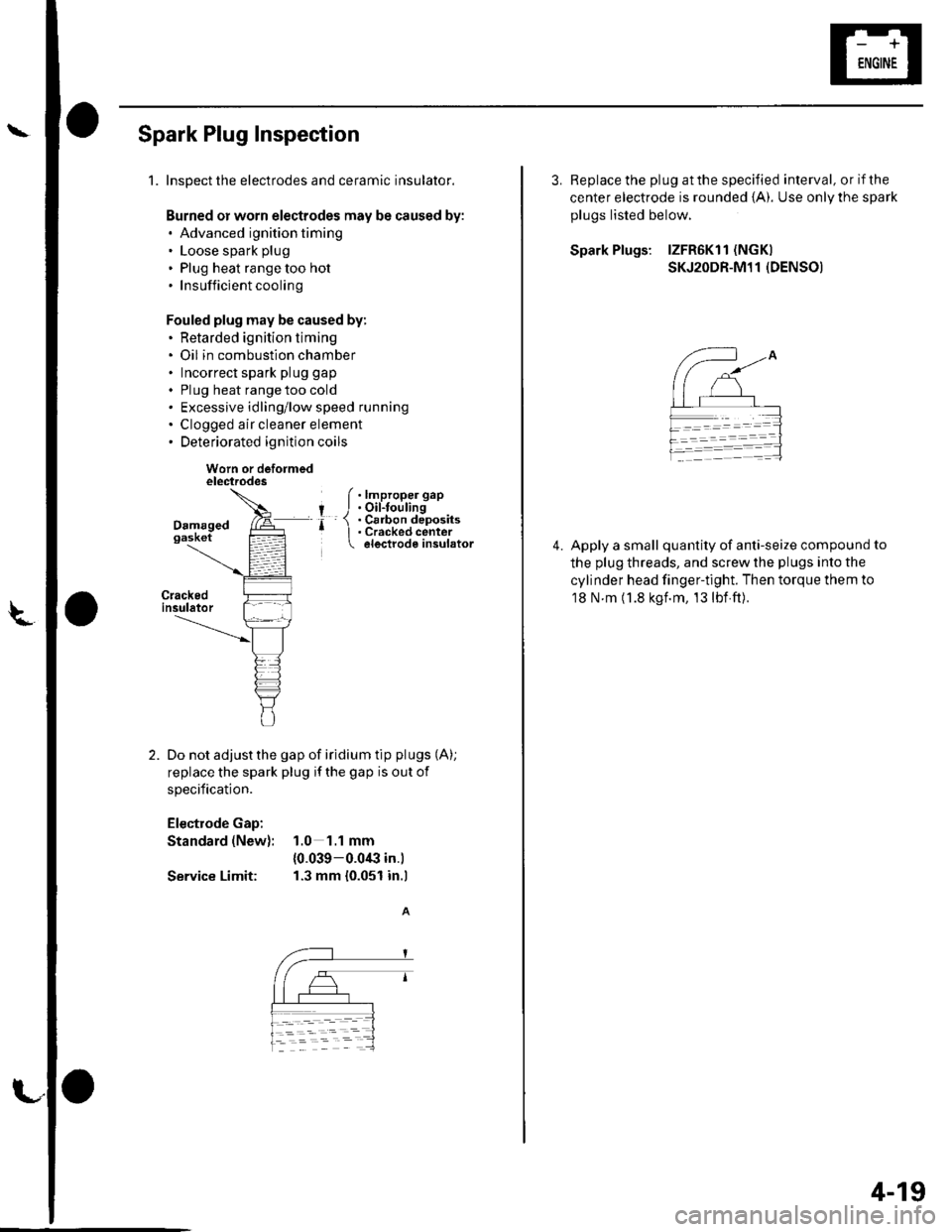
Spark Plug Inspection
1.Inspect the electrodes and ceramic insulator.
Burned or worn electrodes may be caused by:. Advanced ignition timing. Loose spark plug
. Plug heat range too hot.Insufficientcooling
Fouled plug may be caused by:. Retarded ignition timing. Oil in combustion chamber. Incorrect spark plug gap
. Plug heat range too cold. Excessive idling/low speed running. Clogged air cleaner element. Deteriorated ignition coils
Worn or deformedelectrodes
Do not adjust the gap of iridium tip plugs (A);
replace the spark plug if the gap is out of
specification.
Electrode Gap:
Standard (New): 1.0 1.1 mm
{0.039-0.0€ in.)
Service Limit: 1.3 mm {0.051 in.l
f .lmproper gap
I J.Oil-toulingr- 1 . Cs6on deposits' I . Cracked center electrode insulator
L
3. Replace the plug at the specified interval, or if the
center electrode is rounded {A). Use onlV the spark
plugs listed below.
Spark Plugs: lZFR6Kl1 (NGK)
SKJ2ODR-M11 (DENSO)
Apply a small quantity of anti-seize compound to
the plug threads, and screw the plugs into the
cylinder head finger-tight. Then torque them to
18 N m (1.8 kgf.m, 13lbf ft).
4.
4-19
Page 59 of 1139
Gharging System
Charging Circuit Troubleshooting (cont'd)
6. Start the engine. Hold the engine at 3,000 rpm with
no load (in Neutral) until the radiator fan comes on,
then let it idle.
7. Raise the engine speed to 2,000 rpm, and hold it
there.
8. Turn the headlights (high beam) on, and measure
voltage at the under-hood fuse/relay box terminal.
ls the voltage between 13.9 and 15.1 v?
YES-Go to step 9.
NO Repair or replace the alternator components
(see page 4-30).1
9. Read the amperage at '13.5 V.
NOTE: Adjust the voltage by turning the blower
motor, rear window defogger, brake lights. etc. ON.
ls the amperage 604 ot morc?
YES-Alternator/regulator operation is OK. I
NO Repair or replace the alternator components(see page 4-30).1
4-24
\,
Alternator Control System Test
NOTE: After troubleshooting, perform the engine
control module (ECM) idle learn procedure (see page
11-139).
1 . Check for proper operation of the electrical load
detector (ELD) by checking the malfunction
indicator lamp (MlL) (see page 1 l-3). lf a DTC is
present, diagnose and repair the cause before
continuing with this test.
2. Disconnect the engine wire harness 6P connector
from the starter sub harness 6P connector.
3. Start the engine, and turn the headlights (high
beam) ON,
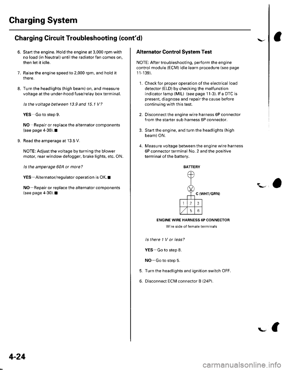
4. Measure voltage between the engine wire harness
6P connector terminal No. 2 and the positive
terminal of lhe battery.
C {WHT/GRN)
ENGINE WIRE HARNESS 6P CONNECTOR
Wire side of female terminals
ls there 1 V or less?
YES Go to step 8.
NO-Go to step 5.
Turn the headlights and ignition switch OFF.
Disconnect ECM connector B (24P).
5.
6.
BATTERY
Page 60 of 1139
\
L
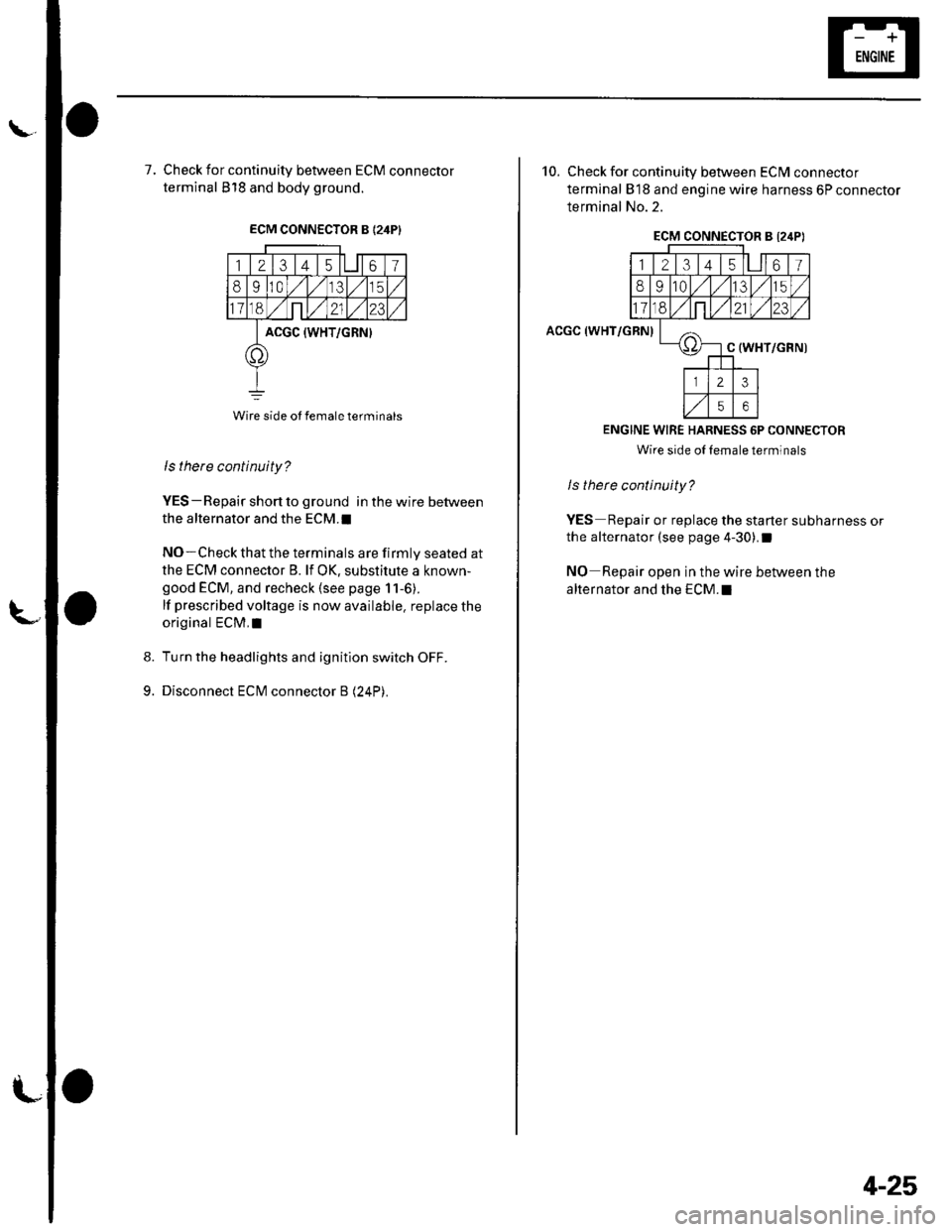
7, Check for continuity between ECM connector
terminal 818 and body ground.
ECM CONNECTOR B {24PI
123 t4 t561
8910,/1,/35
11ont,/2123
ACGC {WHT/GRN}
o
Wire side ot female terminals
9.
ls there continuity?
YES-Repair short to ground in the wire between
the alternator and the ECM.I
NO-Check that the terminals are firmly seated at
the ECM connector B. lf OK, substitute a known-
good ECM, and recheck (see page 11-6).
lf prescribed voltage is now available. replace the
original ECM,I
Turn the headlights and ignition switch OFF.
Disconnect ECM connector B (24P).
10. Check for continuity between ECM connector
terminal 818 and engine wire harness 6P connector
terminal No.2.
ACGC (WHT/GRN)
ECM CONNECTOR B l2,lPI
12314l5lll67
8910t.)15
11on2123
oC (WHT/GRN)
23
56
ENGINE WIRE HARNESS 6P CONNECTOR
Wire side oI lemale terminals
ls therc continuity?
YES Repair or replace the starter subharness or
the alternator (see page 4-30).I
NO Repair open in the wire between the
alternator and the ECM.I
4-25
Page 64 of 1139
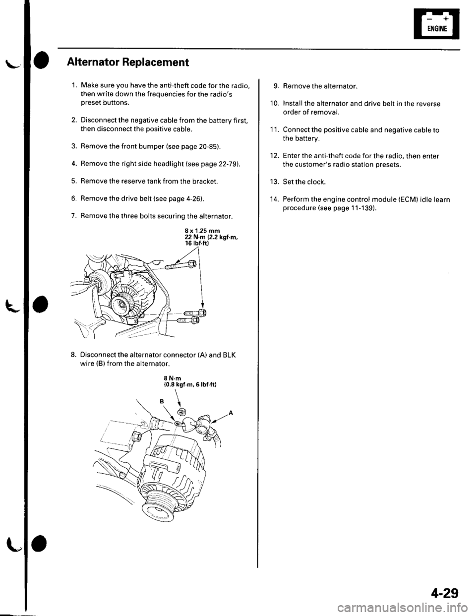
l\-Alternator Replacement
1. Make sure you have the anti-theft code for the radio,
then write down the frequencies for the radio'spreset buttons,
2. Disconnect the negative cable from the battery first,
then disconnect the positive cable.
3. Remove the front bumper (see page 20-85).
4. Remove the right side headlight (see page 22-79).
5. Remove the reserve tank from the bracket.
6. Remove the drive belt (see page 4-26).
7. Remove the three bolts securing the alternator.
8 x 1.25 mm22 N.n 12.2 kgl.m,
Disconnect the alternator connector (A) and BLK
wire (B) from the alternator.
8 N.m10.8 kgf.m,6lbf.ft)
\
6
'I 1.
9.
10.
13.
14.
Remove the alternator.
Installthe alternator and drive belt in the reverse
order of removal.
Connect the positive cable and negative cable to
the battery.
Enter the anti-theft code for the radio, then enter
the customer's radio station presets.
Set the clock.
Perform the engine control module {ECM) idle learn
procedure (see page 11-139).
tt.
4-29
Page 84 of 1139
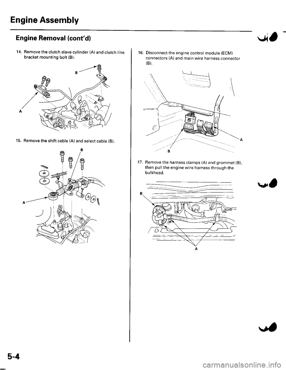
Engine Assembly
Engine Removal (cont'dl
14. Remove the clutch slave cylinder {A) andclutchline
bracket mounting bolt (B).
15. Remove the shift cable (A) and select cable (B).
5-4
..4,
16. Disconnect the engine control module (ECM)
connectors (A) and main wire harness connector(B).
Remove the harness clamps (A) and grommet (B),
then pullthe engine wire harness through the
bulkhead.
't7 .
\l,