remove seats HONDA CIVIC 2002 7.G Workshop Manual
[x] Cancel search | Manufacturer: HONDA, Model Year: 2002, Model line: CIVIC, Model: HONDA CIVIC 2002 7.GPages: 1139, PDF Size: 28.19 MB
Page 101 of 1139
Cylinder Head
Engine Compression Inspection
1. Warm up the engine to normal operating
temperature (cooling fan comes on).
2. Turn the ignition switch OFF.
3. Remove the intake manifold cover (see step 1 onpage 6-22).
4, Disconnect all four injector connectors.
5. Start the engine, and let it run until it stalls.
6. Remove the iour ignition coils (see page 4-18).
7. Remove the four spark plugs.
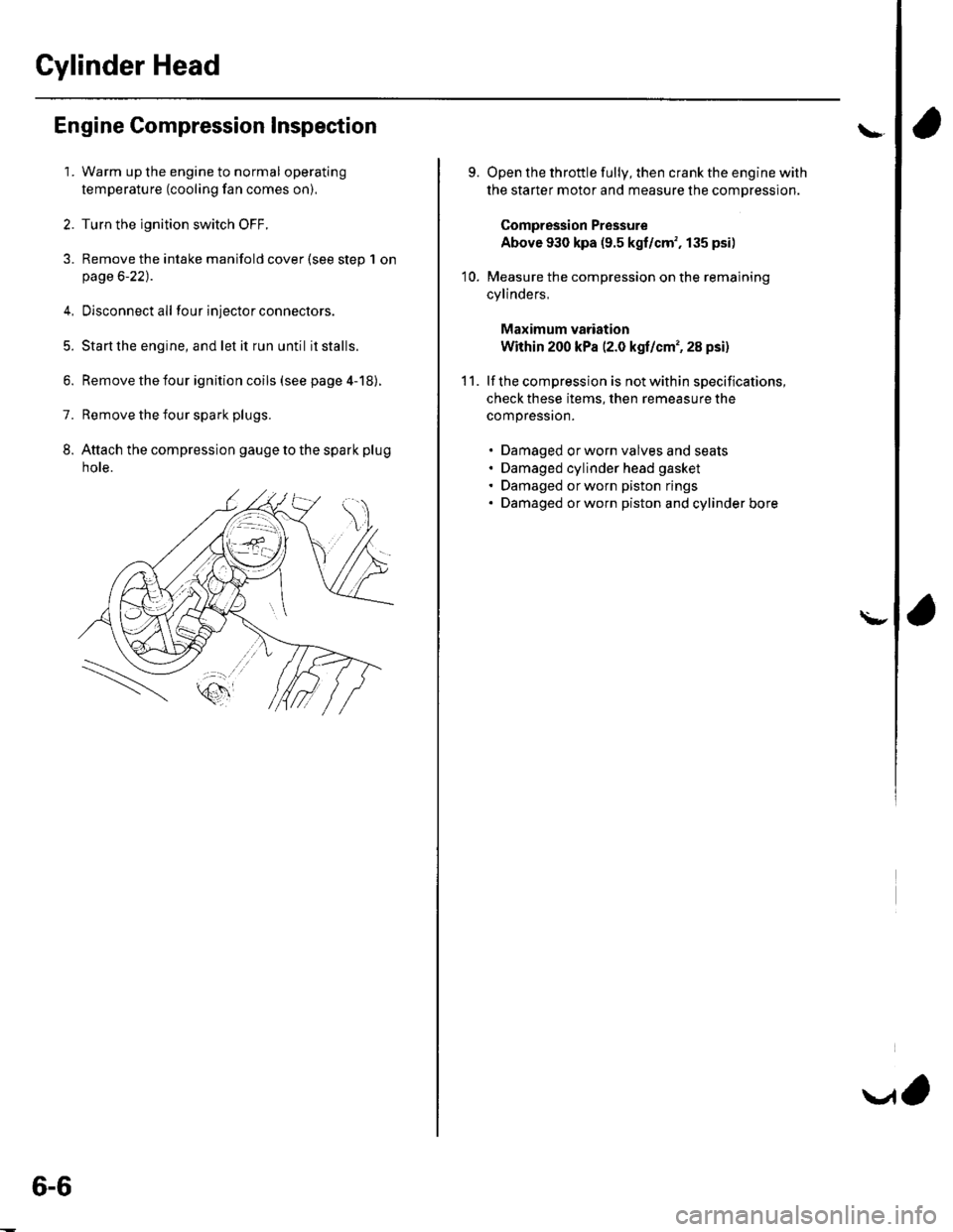
8. Attach the compression gauge to the spark plug
note.
6-6
V,
\
9.
10.
Open the throttle fully, then crank the engine with
the starter motor and measure the compression.
Compression Pressure
Above 930 kpa (9.5 kgf/cm', 135 psi)
Measure the compression on the remaining
cylinders,
Maximum vadation
Within 200 kPa (2.0 kgf/cm', 28 psi)
lf the compression is not within specifications,
check these items, then remeasure the
compressron.
. Damaged orworn valves and seats. Damaged cylinder head gasket. Damaged or worn piston rings. Damaged orworn piston and cylinder bore
11.
\-
Page 128 of 1139
Valve Guide Replacement
Special Tools Required. Valve guide driver, 5.5 mm 07742-0010100. Valve guide reamer, 5.5 mm 07HAH-PJ7o108
1.Inspect valve stem-to-guide clearance (see page 6-
32t.
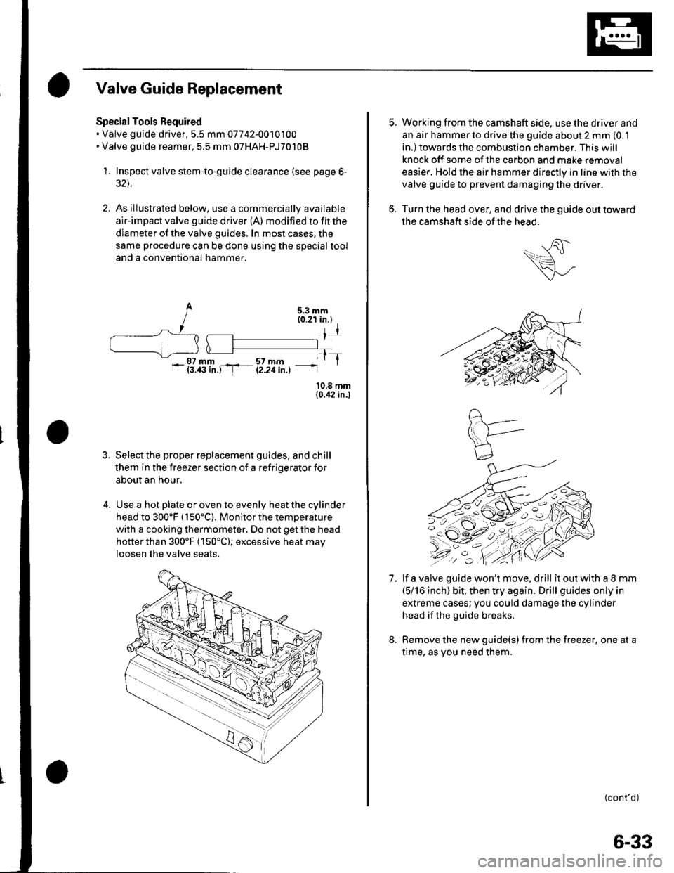
As illustrated below, use a commercially available
air-impact valve guide driver (A) modified to fit the
diameter of the valve guides. In most cases, the
same procedure can be done using the special tool
and a conventional hammer.
10.8 mm{0.,|2 in.)
3. Select the proper replacement guides, and chill
lhem in the freezer section of a refriqerator for
about an hour.
4. Use a hot plate or oven to evenly heat the cylinder
head to 300'F (150"C). Monitor the temperature
with a cooking thermometer. Do not getthe head
hotterthan 300'F (150"C); excessive heat may
loosen the valve seats.
-_|Jfillr-.-4fi'11., -
tT
7.
Working from the camshaft side. use the driver and
an aar hammerto drive the guide about 2 mm (0.1
in.)towards the combustion chamber. This will
knock off some of the carbon and make removal
easier. Hold the air hammer directly in line with the
valve guide to prevent damaging the driver.
Turn lhe head over, and drive the guide out toward
the camshaft side of the head.
lf a valve guide won't move, drill it out with a I mm
(5/16 inch) bit. then try again. Drill guides only in
extreme cases;you could damage the cylinder
head if the guide breaks.
Remove the new guide(s) from the freezer, one at a
time, as vou need them.
(cont'd)
6-33
Page 130 of 1139
Valve Seat Reconditioning
1. Inspect valve stem-to-guide clearance (see page 6-
32). lf the valve guides are worn, replace them (see
page 6-33) before cutting the valve seats.
2. Renew the valve seats in the cylinder head using a
valve seat cutter.
Carefully cut a 45'seat, removing only enough
material to ensure a smooth and concentric seat.
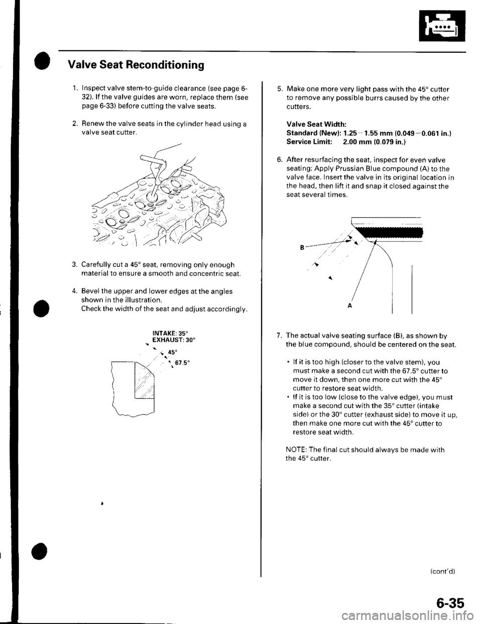
Bevel the upper and lower edges at the angles
shown in the illustration.
Check the width of the seat and adjust accordingly.
INTAKE:35"EXHAUST:30'
3,
4.
- 45'
, { 67.5'
5. Make one more very light pass with the 45" cutter
to remove any possible burrs caused by the other
cutters.
Valve Seat Width:
Standard (New): 1.25 1.55 mm {0.049 0.061 in.)
Service Limit: 2.00 mm (0.079 in.)
6. After resurfacing the seat, inspect for even valve
seating: Apply Prussian Blue compound (A) to the
valve face. Insert the valve in its original location in
the head, then lift it and snap it closed against the
seat several trmes.
1.The actual valve seating surface (B), as shown by
the blue compound, should be centered on the seat.
. lf it is too high (closer to the valve stem), you
must make a second cut with the 67.5' cutter to
move it down, then one more cut with the 45"
cutter to restore seat width.. lf it is too low (close to the valve edge), you must
make a second cut with the 35'cutter (intake
sidel or the 30" cutter (exhaust side) to move it up,
then make one more cut with the 45" cutter to
restore seat width.
NOTE: The final cut should always be made with
the 45'cutter.
(cont'd)
6-35
Page 132 of 1139
Valves, Springs, and Valve Seals Installation
Special Tools Required
Valve spring compressor attachment 07VAE-00101 0A
1. Coat the valve stems with engine oil. lnstall the
valves in the valve guides.
2. Check that the valves move up and down smoothly.
Installthe spring seats on the cylinder head.
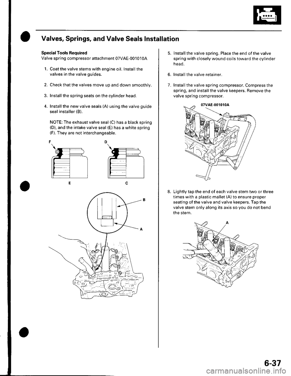
Install the new valve seals (A) using the valve guide
seal installer (B).
NOTE: The exhaust valve seal (C) has a black spring(D), and the intake valve seal (E) has a white spring(F). They are not interchangeable.
6.
lnstallthe valve spring. Place the end ofthe valve
spring with closely wound coils toward the cylinder
n eao.
Install the valve retainer.
Installthe valve spring compressor, Compress the
spring, and install the valve keepers. Remove the
valve spring compressor.
Lightly tap the end of each valve stem two or three
times with a plastic mallet (A) to ensure proper
seating of the valve and valve keepers. Tap the
valve stem only along its axis so you do not bend
the stem.
7.
6-37
Page 172 of 1139
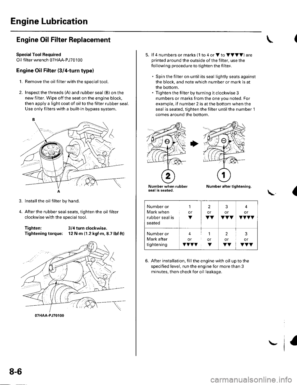
Engine Lubrication
Engine Oil Filter Replacement
Special Tool Fequired
Oil filter wrench 07HAA-PJ70100
Engine Oil Filter (3/4-turn type)
1. Remove the oil filterwiththesDecial tool.
2. Inspect the threads {A) and rubber seal (B) on the
new filter. Wipe off the seat on the engine block,
then apply a light coat of oil to the filter rubber seal.
Use only filters with a built-in bypass system.
Installthe oilfilter by hand.
After the rubber seal seats, tighten the oil filter
clockwise with the special tool.
Tighten: 3/4 turn clockwise.
Tightening torque: 12 N.m (r.2 kgf.m,8.7 lbf.ft)
07HAA-PJ70100
8-6
\,
5. lf 4 numbers or marks (1 to 4 or V to VVVV) are
printed around the outside of the filter, use the
following procedure to tighten the filter.
. Spin the filter on until its seal lightly seats against
the block, and note which number or mark is at
the bottom.. Tighten the filter by turning it clockwise 3
numbers or marks from the one you noted. For
example, if number 2 is at the bottom when the
seal is seated, tighten the filter until the number 1
comes around the bottom.
Number when rubberseal is seated.Number after tightening.
(\..
6. After installation, fill the enginewith oil uptothe
specified level, run the engine for more than 3
minutes, then check for oil leakage.
Number or
Mark when
rubber seal is
1
or
V
2
or
VV
3
or
VVV
4
or
VVVV
Number or
Mark after
tightening
41
or or
vvvv. v
2
or
VV
3
or
VVV
Page 574 of 1139
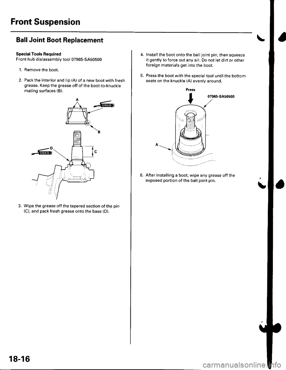
Front Suspension
Ball Joint Boot Replacement
Special Tools Required
Front hub dis/assembly tool 07965-5450500
1. Remove the boot.
2. Pack the interior and lip (A) of a new boot with fresh
grease. Keep the grease off of the boot-to-knuckle
mating surfaces (B).
-6r
rffi
€l
--B
Wipe the grease off the tapered section of the pin
(C), and pack fresh grease onto the base (D).
tI
18-16
Inst€ll the boot onto the ball joint pin, then squeeze
it gently to force out any air. Do not let dlrt or other
foreign materials get into the boot.
Press the boot with the special tool until the bottom
seats on the knuckle (A) evenly around.
pross
07965-SA50500
6.After installing a boot, wipe any grease off the
exposed portion of the ball joint pin.
i
Page 673 of 1139
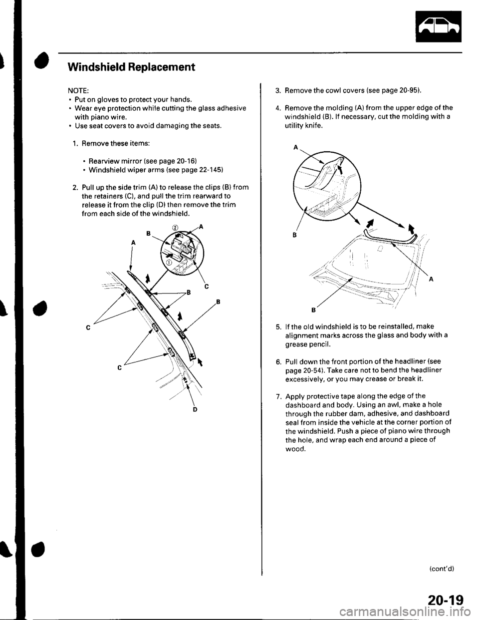
Windshield Replacement
NOTE:. Put on gloves to protect your hands,. Wear eye protection while cutting the glass adhesive
with piano wire.. Use seat covers to avoid damaging the seats.
1. Remove these items:
. Rearview mirror (see page 20-16). Windshield wiper arms (see page 22-145)
2. Pull up the side trim (A) to release the clips (B) from
the retainers (C), and pull the trim rearward to
release it from the cliD (D) then remove the trim
from each side of the windshield.
4.
Remove the cowl covers (see page 20-95).
Remove the molding (A) from the upper edge of the
windshield (B). lf necessary, cut the molding with a
utility knife.
lf the old windshield is to be reinstalled, make
alignment marks across the glass and body with a
grease pencil.
Pull down the front portion of the headliner (see
page 20-54). Take care not to bend the headliner
excessively, or you may crease or break it.
Apply protective tape along the edge of the
dashboard and body. Using an awl, make a hole
through the rubber dam, adhesive. and dashboard
seal from inside the vehicle at the corner ponion ot
the windshield. Push a piece of piano wire through
the hole, and wrap each end around a piece of
wood.
(cont'd)
7.
20-19
Page 705 of 1139
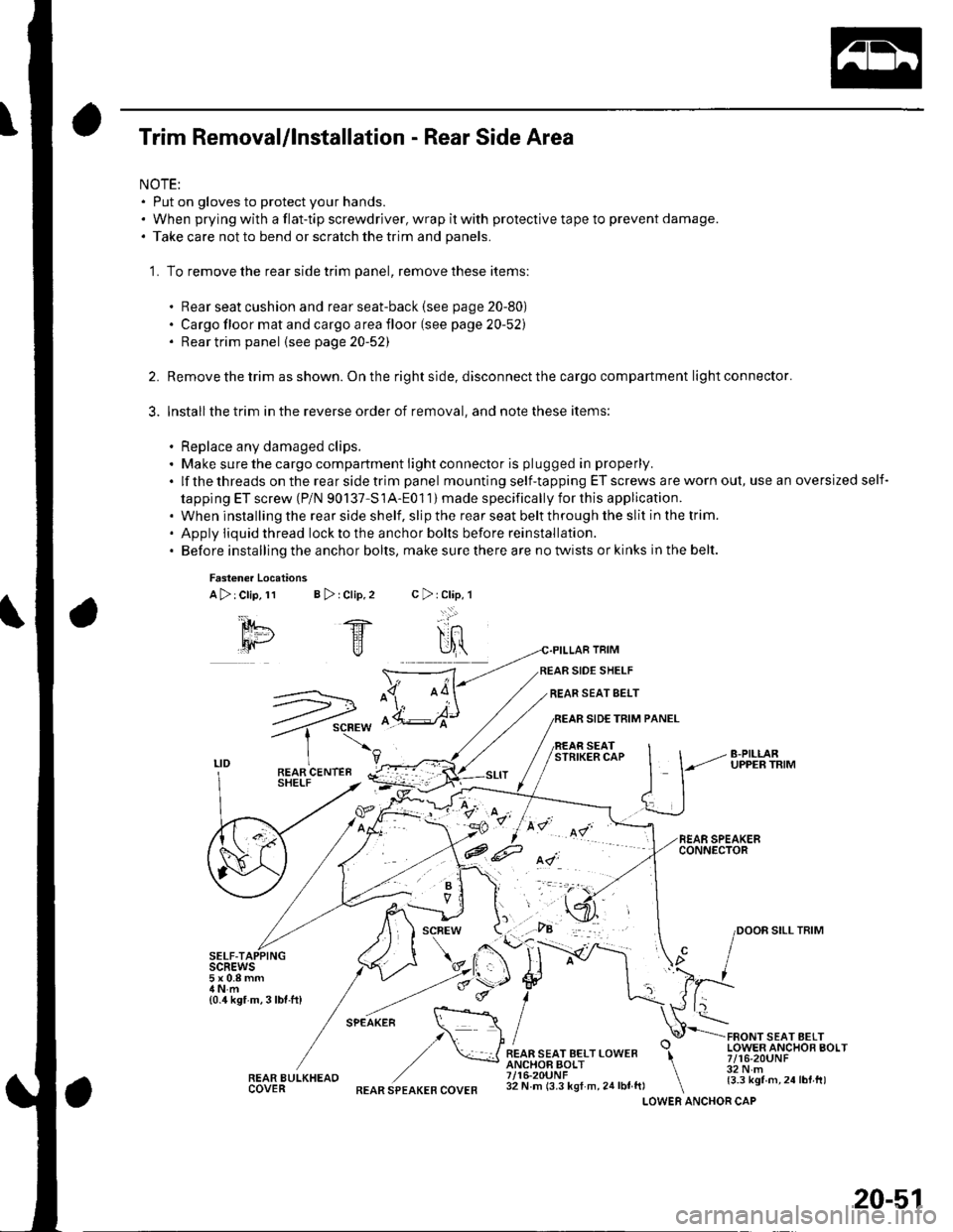
Trim Removal/lnstallation - Rear Side Area
NOTE:. Put on gloves to protect your hands.. When prying with a flat-tip screwdriver, wrap it with protective tape to prevent damage.. Take care not to bend or scratch the trim and panels.
'1. To remove the rear side trim panel, remove these items:
. Rear seat cushion and rear seat-back (see page 20-80). Cargo floor mat and cargo area floor (see page 20-52). Rear trim panel {see page20-52)
Remove the trim as shown. On the right side, disconnect the cargo compartment light connector.
Installthe trim in the reverse order of removal, and note these items:
. Replace any damaged clips.. Make sure the cargo compartment light connector is plugged in properly.
.lfthethreadsontherearsidetrimpanel mounting self-tapping ET screws are worn out, use an oversized self-
tapping ET screw (P/N 90137-S1A-Eo1 1) made specifically for this application.. When installing the rear side shelf, slip the rear seat belt through the slit in the trim.' Apply iiquid thread lockto the anchor bolts before reinstallation.. Before installing the anchor bolts, make sure there are no twists or kinks in the belt.
2.
3.
Fasten€r Locations
A>:Clip,11 B > rClip,2
SELF-TAIscREws5x0.8mm
{0.4 kgf m,3lbf.ft)
REAR BULKHEAOCOVER
TRIM
SIDE SHELF
REAR SEAT SELT
SIDE TRIM PANEL
SEATSTRIKER CAP
FRONT SEAT AELTLOWER ANCHOR BOLT7/16-20UNF32 N.m{3.3 kgf m,24lbt.tt)
c>rClap,l
-..:.:'
SILL TRIM
.F.-*-.n. \::: :\,/ I
,/ \*JREAR SEAT BELT LOWER \ANCHOF BOLT \7/16-20UNF \32 N m (3.3 kgf m, 24 lbf ft, \LOWERREAR SPEAKER COVERANCHOR CAP
20-51
Page 709 of 1139
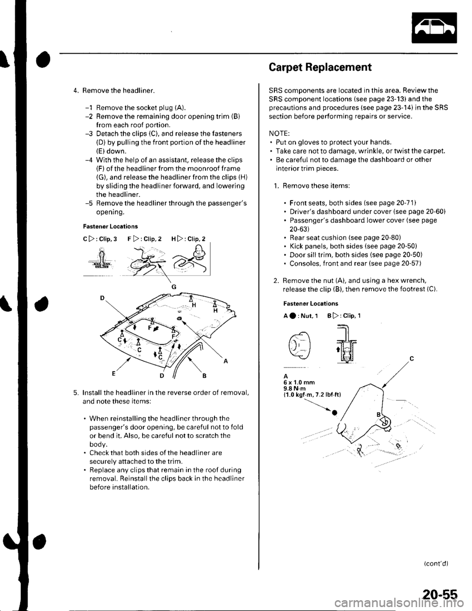
4. Remove the headliner.
-1 Remove the socket plug (A).
-2 Remove the remaining door opening trim {B}
from each roof portion.
-3 Detach the clips (C), and release the fasteners
(D) by pulling the front portion ofthe headliner
(E) down.-4 With the help of an assislant, release the clips(F) of the headliner from the moonroof frame
(G), and release the headliner from the clips (H)
by sliding the headliner forward, and lowering
the headliner.-5 Remove the headliner through the passenger's
opening.
Fastener Locations
C>:Clip,3
ao
5.Install the headliner in the reverse order of removal,
and note these items:
. When reinstalling the headliner through the
passenger's door opening, be careful not to fold
or bend it, Also, be careful not to scratch the
DOOy.. Check that both sides of the headliner are
securely attached to the trim.. Replace any clips that remain in the roof during
removal. Reinstallthe clips back in the headliner
before installation.
F>:Clip,2 H>:Clip,2
Carpet Replacement
SRS components are located in this area. Reviewthe
SRS component locations (see page 23-13) and the
precautions and procedures (see page 23-14) in the SRS
section before performing repairs or service.
NOTE:. Put on gloves to protect your hands.. Take care not to damage, wrinkle. or twist the carpet.. Be careful not to damage the dashboard or other
interior trim pieces.
1. Remove these items:
. Front seats, both sides (see page 20-111. Driver's dashboard under cover (see page 20-60). Passenger's dashboard Iower cover (see page
20-631. Rear seat cushion (see page 20-80). Kick panels, both sides (see page 20-50). Door silltrim, both sides (see page 20-50). Consoles, front and rear (see page 20-57)
2. Remove the nut (A), and using a hex wrench,
release the clip (B), then remove the footrest (C).
Fastener Locations
Aa:Nut,1 B):Clip,'l
--'1 I
-- -JrL
tj I ;tt4f=\-/ l[il
A6x1.0mm9.8Nm11.0 kgf m,7.2 lbf.ft)
-o
(cont'd)
20-55
Page 726 of 1139
Seats
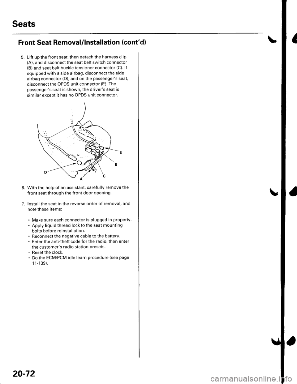
Front Seat Removal/lnstallation (cont'dl
Lift up the front seat, then detach the harness clip(A). and disconnect the seat belt switch connector(B) and seat belt buckle tensioner connector (C). lf
equipped with a side airbag, disconnect the side
airbag connector (D), and on the passenger's seat,
disconnect the OPDS unit connector (E). The
passenger's seat is shown, the driver's seat is
similar except it has no OPDS unit connector.
With the help of an assistant, carefully remove the
front seat th rough the front door opening.
Installthe seat in the reverse order of removal, and
note these rtems:
. l\4ake sure each connector is plugged in properly.
. Apply liquid thread lock to the seat mounting
bolts before reinstallatlon.. Reconnect the negative cable to the battery.. Enter the anti-theft code for the radio, then enter
the customer's radio station presets.
. Reset the clock.. Do the ECM/PCM idle learn procedure (see page
1 1-139).
6.
7.
20-72