piston HONDA CIVIC 2003 7.G Workshop Manual
[x] Cancel search | Manufacturer: HONDA, Model Year: 2003, Model line: CIVIC, Model: HONDA CIVIC 2003 7.GPages: 1139, PDF Size: 28.19 MB
Page 16 of 1139
nqtne
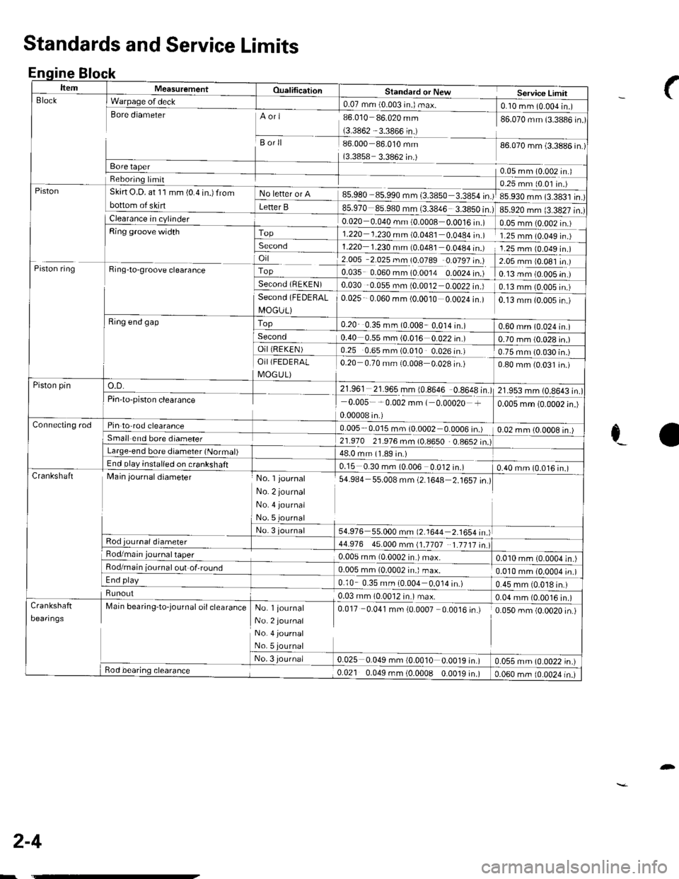
ItemMeasurementOualificationStandard or NewService LimirBlock
Piston
I Warpage of deck0.07 mm (0.003 in.) max.foro.. (ulur^^-"1tsore diameterAori
Borll
(3.3858 3.3862 in.)
85.980 85.990 mm (3.3850 3.3854 in.)
l-il?0 €s.980 r"i33846
86.010 86.020 mm
(3.3862 3.3866 in.)
86.000 86.010 mm
86.070 mm (3.3886 in.)
86.070 mm (3.3886 in.)
0.05 mm (0.002 In.J
85.920 mm (3.3827 in.)
0.25 mm (0 0l in.)
85.930 mm (3.383'l in.)
Reboring lrmit
Skirt O.D. at 11 mm (0.4 in.) from
bottom of skirtF" btt"' "' A
Letter B
0.020 0.040 mm (0 0008 0.0016 in.)0.05 mm {0.002 in.)Top1.220 1.230 mm (0.0481 0.0484 in.)1.25 mm 10.049 rn )Second1.220 1.230 mm (0.0481 0 0a84In.)1.25 mm 10.049 in.)
Piston ring
lFis,.€-"'"
",";"*
L-Ring end gap
o.D.
i 2.005 2.025 mm (0.0789 0.0797 in.)
fo.o:s o.oto.rn lo.oora o.ooza i.'.f
EO3t 0 056 rn. {OJ01r OOO2 i")
?.09rrl9.091lt )
0.13 mm (0.005 in )
0.13 mm (0.005 in.)Second (FEDEHAL
I\4OGUL)
Top
0.025 0.060 mm (0.0010 0.0024 in.)0.13 mm (0.005 in )
0.20 0.35 mm (0.008 0.014 in.)0.60 mm (0.024 in.)Second0.40 0.55 mm {0.016 0.022 in.)0.70 mm (0.028 in.)OiI (REKEN)
21.961 21.965 mm {0.8646 0.8648 in.)
0.25 0.65 mm (0.010 0.026 in.)
0 20 0.70 mm i0.008 0.028 in.)
0.75 mm (0.030 in.)OiI(FEDERAL
I\4OG U L)0.80 mm 10.031 in.)
Piston pin21.953 mm l0 8643 inPin'to-piston clearance0.005-*0.002 mm ( 0.00020 +
0.00008 in.)
0.005 mm (0.0002 in.)
Connecting rodPin to-rod clearance0.005 0.015 mm (0.0002 0.0006 in.)0.02 mm lO 0OO8 in ISmall end bore diameler21.970 21.976 mm (0.8650 0.8652 in.)Large-end bore diameter (Normal)48.0 mm (1.89 in.)End play inslalled on crankshaft0.15 0.30 mm (0.006 0.012 in.)0.40 mm (0.016 in.)CrankshaftMain journal diameter
Rod journal diameter
No. l journal
No. 2 journal
No. 4 journal
No. 5 journal
No. 3 journal
s4.e84 s5.008 mm (2.1648=16illl
54.976 55.000 mm (2.1644 2-1654in)
44.976 45.000 mm (1.1707 1.1717 in.lRod/main0.005 mm 10.0002 in.) max.0.010 mm (0.0004 in.)Rod/main iournal out of,round0.005 mm (0.0002 in.) max.0.010 mm (0.0004 in.)End play0.10 0.35 mm (0.004 0.0'14 in.)0.45 mm 10.018 in.)Runout..-'.:�--'+0.03 mm (0.0012 in.) max.0.04 mm {0.0016 in.)
Deaflngs
Marn oear,n9-toJournat ott ctearanceNo. l journal
No. 2 journal
No. 4 journal
No.5
No. 3 journa/
0.017 0.041 mm (0.0007 0.0016 in.)
q0rr034, -rn {O'o010 0-o01r|"tl
0.050 mm (0.0020 in.)
0.055 mm (0.0022 in.)Bod bearing clearance0.021 0.049 mm (0.0008 0.0019 in.)0.060 mm (0.0024 in.)
Standards and Service Limits
Enqine Block
_f
c_a
2-4
-
Page 22 of 1139
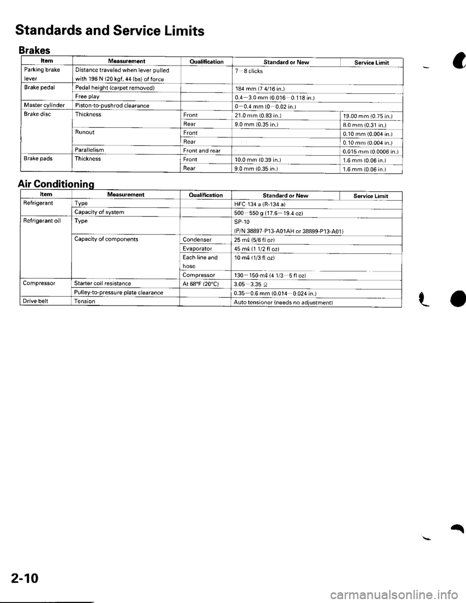
ItemM€asurementOualificationStandard or NewService LimitParking brake
lever
Distance traveled when lever pulled
with 196 N (20 kgf, 44 lbs) ol force
7 8 clicks
Brake pedalPedal height (carpet removed)184 mm (7 4/16 in.)
Free play0.4 3.0 mm (0 016 0 '118 in.)Master cylinderPiston-to-pushrod clearance0 0.4 mm (0 0.02 in.)Erake discThicknessFront21.0 mm (0.83 in.)19.00 mm (0.75 in.)
Rear9.0 mm {0.35 in.)8-0 mm (0.31 in.iRunoutFront0.10 mm (0.004 in.)
Rear0.10 mm (0.004 in.)ParallelismFront and rear0.015 mm (0.0006 in.)Brake padsThicknessFront10.0 mm (0.39 in.)1.6 mm (0.06 in.)
llear9.0 mm {0.35 in.)1.6 mm (0.06 in.)
Standards and Service Limits
Brakes
a
e-o
Air Gonditionin
ItemMoasurementOualilicationStandard or New Service LimitRefrige.antTvpeHFC 134 a (B-134 a)
Capacity of system500 550 g 117.6 19.4 oz)Refrigerant oilTypeSP 1O
(P/N 38897-P13-A01AH or 38899-P13-A01 )Capacity ofcomponentsCondenser25 m0, 15/6 fl ozl
Evaporator45 mA 11 1/2 fl ozt
Each line and
hose
10 m0 (1/3 fl or)
Compressor130 150 m014 1/3 5floz)CompressorStarter coil resistanceAt 68"F (20"C)3.05 3.35 0Pulley-to-pressure plate clearance0.35 0.6 mm (0.014 0.024 in.)Drive beltAuto tensioner lneeds no adjustment)
2-10
q
Page 28 of 1139
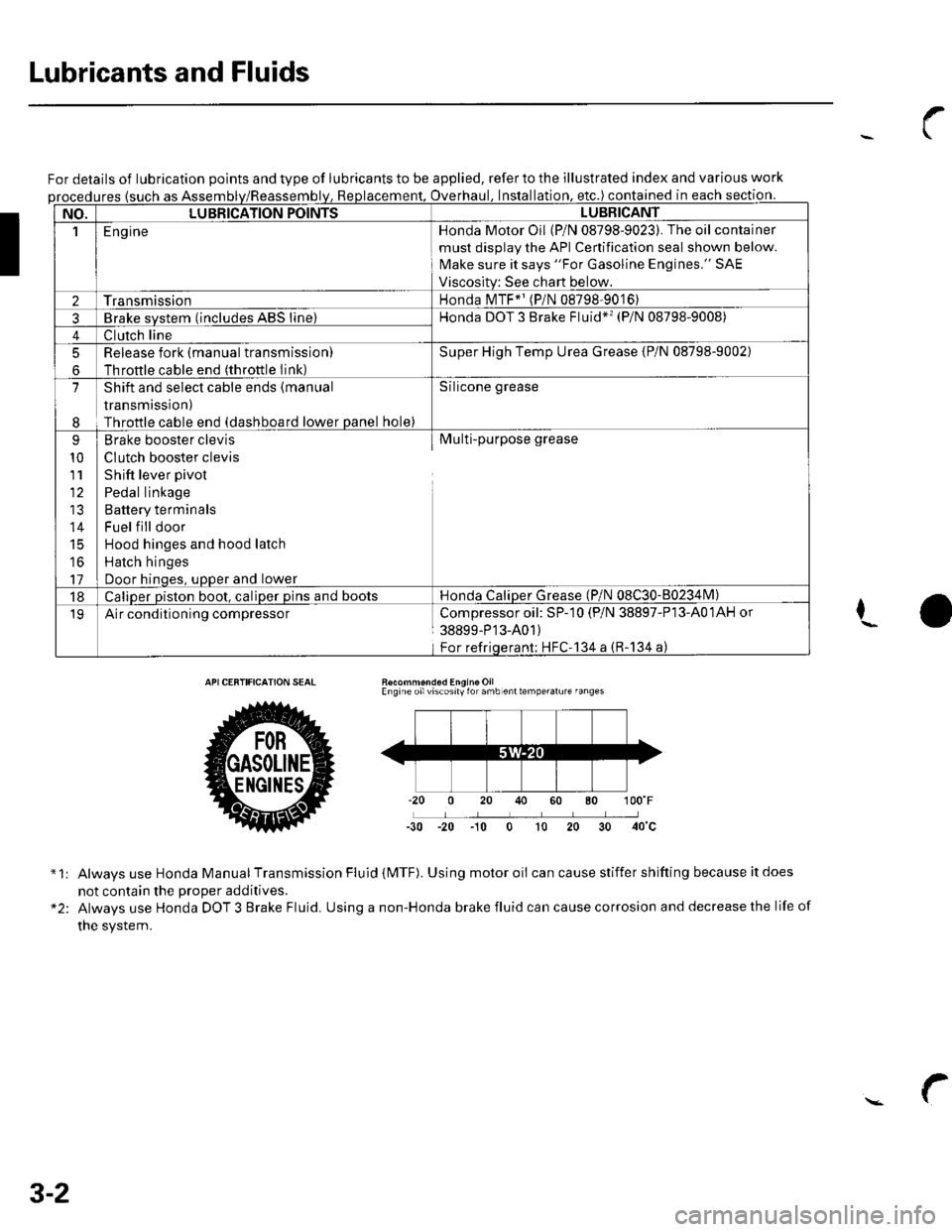
Lubricants and Fluids
For details of lubrication points and type of lubricants to be applied, refer to the illustrated index and various work
ures {such as Assemoverhaul. lnstallation. etc.) contained in each section.
NO.LUBBICATION POINTSLUBBICANT
1E ng ineHonda Motor Oil (P/N 08798-9023). The oil container
must disolav the API Cenification seal shown below.
Make sure it says "For Gasoline Engines." SAE
Viscositv: See chart below.
2TransmissionHonda MTF*' (P/N 08798-9016)
3Brake svstem (includes ABS line)Honda DOT 3 Brake Fluid*'� (P/N 08798-9008)
4Clutch line
5
6
Release fork (manual transmissionl
Throftle cable end (throttle Iink)
Super High Temp Urea Grease {P/N 08798-9002)
7
I
Shift and select cable ends (manual
transmission)
Throttle cable end (dashboard lower panel hole)
Silicone grease
9
10
111'
14
16
17
Brake booster clevis
CIutch booster clevis
Shift lever pivot
Pedal linkage
Battery terminals
Fuel f ill door
Hood hinges and hood latch
Hatch hinges
Door hinoes, uoDer and lower
Multi-purpose grease
18Caliper piston boot, caliper pins and bootsHonda CaliDer Grease (P/N 08C30-80234lvl)
19Air conditioning compressorCompressoroil: SP-10 (P/N 38897-P13-A01AH or
38899-P'13-A01)
For refriqerant; HFC'134 a (R-134 a)
I
Recommond6d Engine OilEngine oilviscosily for amb enttemperalure fanges
-30 -20 -10 0 t0 20
*1:
"2:
Always use Honda Manual Transmission Fluid (MTF). Using motor oii can cause stiffer shifting because it does
not contain the Drooer additives.
Always use Honda DOT 3 Brake Fluid. Using a non-Honda brake fluid can cause corrosion and decrease the life of
the system.
3-2
Page 101 of 1139
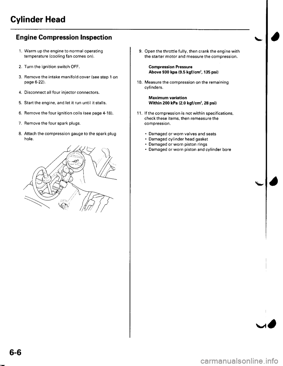
Cylinder Head
Engine Compression Inspection
1. Warm up the engine to normal operating
temperature (cooling fan comes on).
2. Turn the ignition switch OFF.
3. Remove the intake manifold cover (see step 1 onpage 6-22).
4, Disconnect all four injector connectors.
5. Start the engine, and let it run until it stalls.
6. Remove the iour ignition coils (see page 4-18).
7. Remove the four spark plugs.
8. Attach the compression gauge to the spark plug
note.
6-6
V,
\
9.
10.
Open the throttle fully, then crank the engine with
the starter motor and measure the compression.
Compression Pressure
Above 930 kpa (9.5 kgf/cm', 135 psi)
Measure the compression on the remaining
cylinders,
Maximum vadation
Within 200 kPa (2.0 kgf/cm', 28 psi)
lf the compression is not within specifications,
check these items, then remeasure the
compressron.
. Damaged orworn valves and seats. Damaged cylinder head gasket. Damaged or worn piston rings. Damaged orworn piston and cylinder bore
11.
\-
Page 102 of 1139
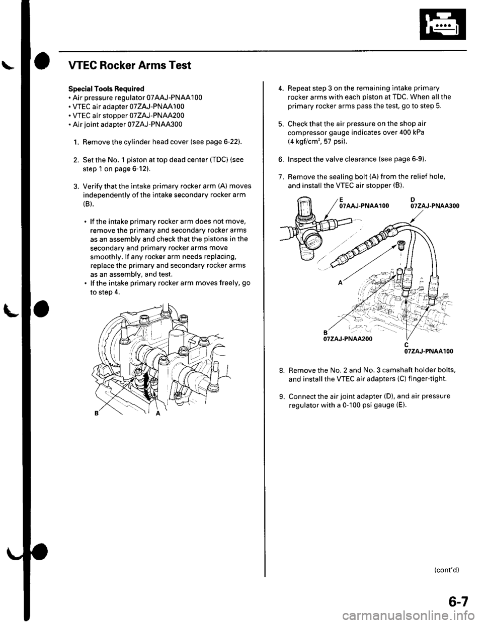
WEC Rocker Arms Test
Special Tools Required. Air pressure regulator 07AAJ-PNAA100. VTEC air adaoter 07ZAJ-PNAA100. WEC air stoDoer 07ZAJ-PNAA200. Air joint adapter 07ZAJ-PNAA300
1. Remove the cylinder head cover (see page 6-22).
2. Set the No. 1 piston at top dead center (TDC) (see
step 1 on page 6-12).
3. Verify that the intake primary rocker arm (A) moves
independently of the intake secondary rocker arm
(B).
. lf the intake primary rockerarm does not move,
remove the primary and secondary rocker arms
as an assembly and check that the pistons in the
secondary and primary rocker arms move
smoothly. lf any rocker arm needs replacing,
replace the primary and secondary rocker arms
as an assemblv, and test.. lfthe intake primary rocker arm moves freely, go
to step 4.
6.
Repeat step 3 on the remaining intake primary
rocker arms with each piston at TDC. When all the
primary rocker arms pass the test, go to step 5.
Check that the air pressure on the shop air
compressor gauge indicates over 400 kPa
(4 kgflcm', 57 psi).
Inspect the valve clearance (see page 6-9).
Remove the sealing bolt (A)from the relief hole,
and install the VTEC air stopper (B).7.
OTAAJ.PNAAlOODOTZAJ-PNAA3OO
Remove the No. 2 and No. 3 camshaft holder bolts,
and installthe VTEC air adapters (C) finger-tight.
Connect the air joint adapter (D), and air pressure
regulator with a 0-100 psi gauge (E).
(cont'd)
OTZAJ.PNAAlOO
6-7
Page 103 of 1139
Cylinder Head
WEC Rocker Arms Test (cont'dl
'10. Loosen the valve on the regulator, and apply thespecified air pressure.
Specified air pressure:
290 kPa 13.0 kgt/cm', 42 psi)
NOTE: lf the synchronizing piston does not moveafter applying air pressure; move the primary orsecondary rocker arm up and down manually byrotating the crankshaft clockwise.
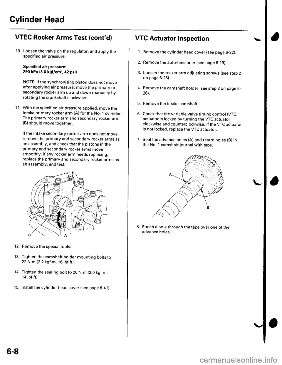
11. With the specified air pressure applied, move theintake primary rocker arm (A)forthe No, 1 cylinder.The primary rocker arm and secondary rocker arm(B) should move together.
lf the intake secondary rocker arm does not move,
remove the primary and secondary rocker arms asan assembly, and check that the pistons in theprimary and secondary rocker arms move
smoothly. lf any rocker arm needs replacing,
replace the primary and secondary rocker arms asan assembly, and test.
Remove the special tools.
Tighten the camshaft holder mounting bolts lo22N m 12.2 kgf.m, 16 lbf.ft).
Tighten the sealing boltto 20 N.m (2.0 kgf.m,
14 tbf.ft).
Installthe cylinder head cover (see page 6-41).
12.
13.
14.
t5.
6-8
VTG Actuator Inspection
'11. Remove the cylinder head cover (see page 6-22lr.
2. Remove the auto-tensioner (see page 6-19).
3. Loosen the rocker arm adjusting screws lsee step 2on page 6-26).
4. Remove the camshaft holder (see step 3 on page 6-
26t.
5. Remove the intake camshaft.
6, Check that the variable valve timing control (VTC)
actuator is locked by turning the VTC actuator
clockwise and counterclockwise. lf the VTC actuatoris not locked, replace the VTC actuator.
7. Seal the advance holes (A)and retard holes (B) in
the No. 1 camshaft journal with tape.
Punch a hole through the tape over one of theadvance holes.
Page 104 of 1139
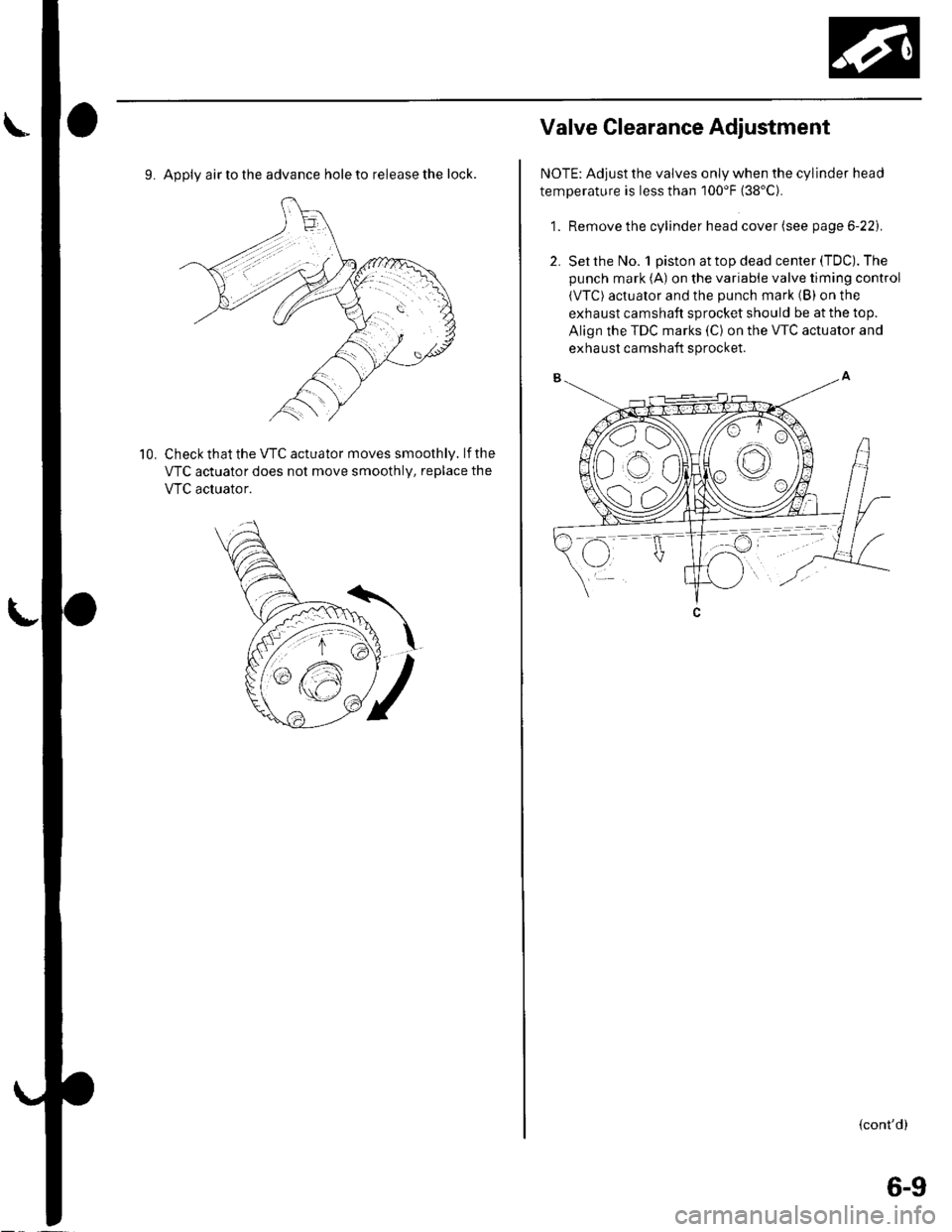
9. Apply air to the advance hole to release the lock.
Check that the VTC actuator moves smoothly. lf the
VTC actuator does not move smoothly, replace the
VTC acluator.
10.
Valve Glearance Adiustment
NOTE: Adjust the valves only when the cylinder head
temperature is less than 100'F (38'C).
1. Remove the cylinder head cover (see page 6-22).
2. Set the No. 1 piston at top dead center (TDC). The
punch mark (A) on the variable valve timing control
(VTC) actuator and the punch mark (B) on the
exhaust camshaft sprocket should be at the top.
Align the TDC marks (C) on the VTC actuator and
exhaust camshaft sprocket.
{cont'd)
6-9
Page 123 of 1139
Cylinder Head
1.
2.
Rocker Arms and Shafts Inspection
Remove the rocker arm assembly (see page 6-26).
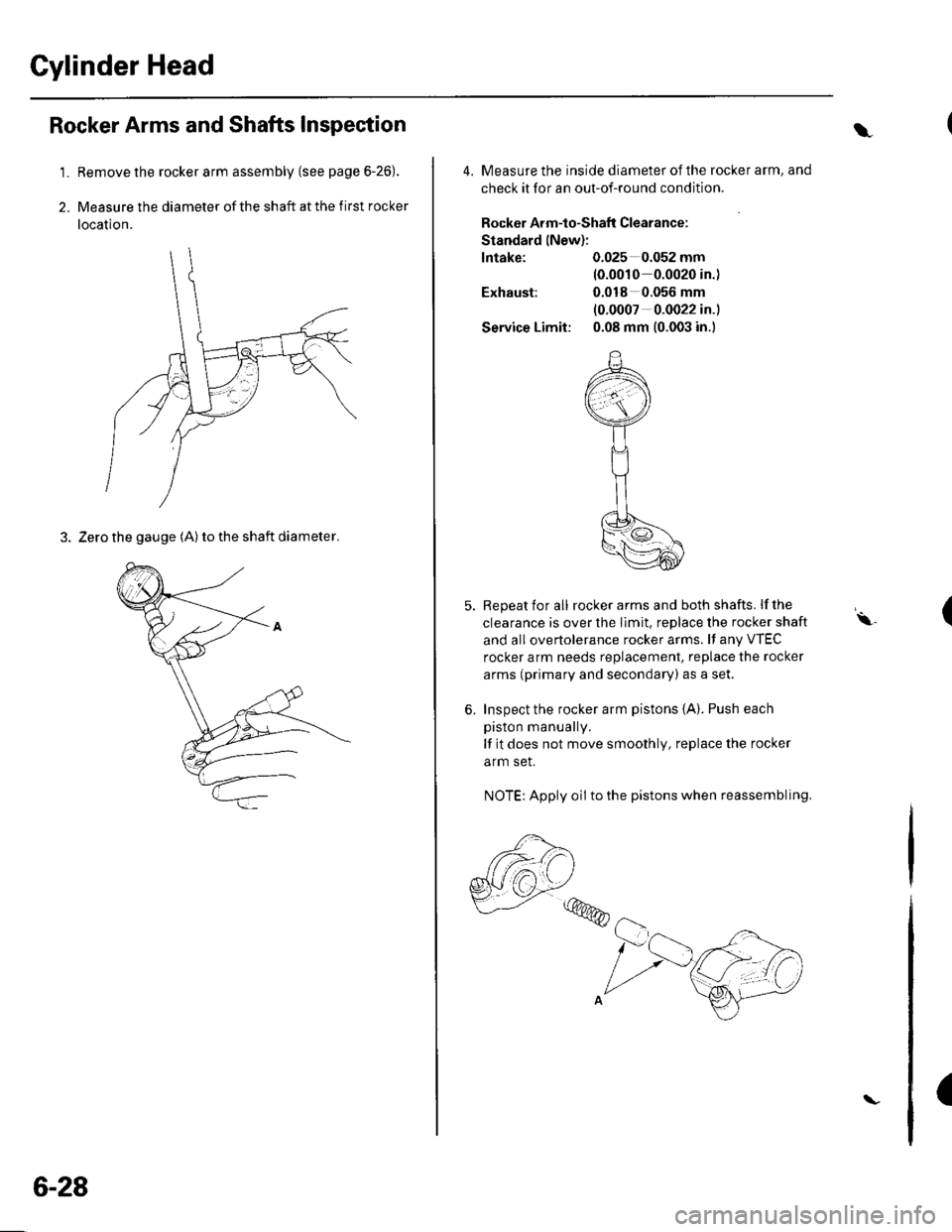
Measure the diameter of the shaft at the first rocker
location.
3. Zero the gauge (A) to the shaft diameter.
6-28
\
4. Measure the inside diameter ofthe rocker arm, and
check it for an out-of-round condition.
Rocker Arm-to-Shaflt Clearance:
Standard lNew):
lntake: 0.025 0.052 mm(0.0010 0.0020 in.)
Exhaust: 0.018 0.056 mm
(0.0007 0.0022 in.)
Service Limit: 0.08 mm (0.003 in.)
5. Repeat for all rockerarms and both shafts. lfthe
clearance is over the Ilmit. replace the rocker shaft
and all overtolerance rocker arms. lf any VTEC
rocker arm needs replacement, replace the rocker
arms (primary and secondary) as a set.
6. Inspect the rocker arm pistons {A}. Push each
piston manually.
lf it does not move smoothly, replace the rocker
arm set.
NOTE: Apply oil to the pistons when reassembling.
,,,@@
(\.
(
Page 139 of 1139
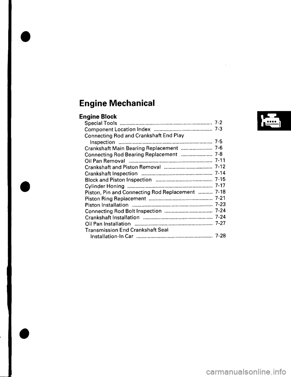
Engine Mechanical
Engine Block
Soecial Tools ............. 7 -2
Comoonent Location Index ......................................... 7-3
Connecting Rod and Crankshaft End Play
InsDection .............. 7-5
Crankshaft Main Bearing Replacement ...................... 7-6
Connecting Rod Bearing Replacement ...................... 7-8
Oil Pan Removal ....................... .......... 7-11
Crankshaft and Piston Removal ........ 7-12
Crankshaft Inspection ........................ 7-14
Block and Piston Insoection ........................................ 7-15
Cyfinder Honing ............ .".................... 7 -'17
Piston, Pin and Connecting Rod Replacement .......... 7-18
Piston Ring Replacement ................... 7 -21
Piston lnstallation .................... ........... 7-23
Connecting Rod Bolt Inspection .......' 7 -24
Crankshaft lnstallation .....................'. 7-24
Oil Pan lnstallation .................. ........... 7 -27
Transmission End Crankshaft Seal
lnstallation-ln Car ................... ........' 7 -28
Page 142 of 1139
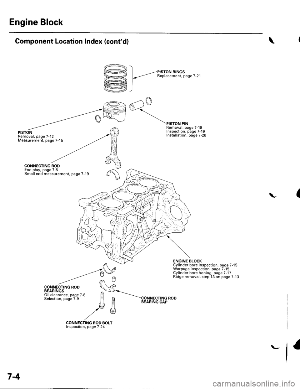
Engine Block
Component Location Index (cont'd)
/^., \
D->< | _,-ersroru nrrucs
Y1 l-"t Benlacement. Page 7-21
rkrej, I
ffil
rG AalQ
[=l^oJ
\
PISTONRemoval, page 7-'12Measurement, page 7-15
PISTON PINRemoval, page 7-18Inspection, page 7-19Installation, page 7,20
f,
6
CONNECTING RODEnd play, page 7-5Small end measurement, page 7-19
CONNECTING ROD
ENGINE BLOCKCylinder bore inspection, page 7-'15Warpage inspection, page 7-15Cylinder bore honing, page 1-11Ridge removai, step 13 on page 7-13
(\
CONNECTING ROD BOLTlnspectaon, page 7 24
7-4