piston HONDA CIVIC 2003 7.G Owner's Manual
[x] Cancel search | Manufacturer: HONDA, Model Year: 2003, Model line: CIVIC, Model: HONDA CIVIC 2003 7.GPages: 1139, PDF Size: 28.19 MB
Page 175 of 1139
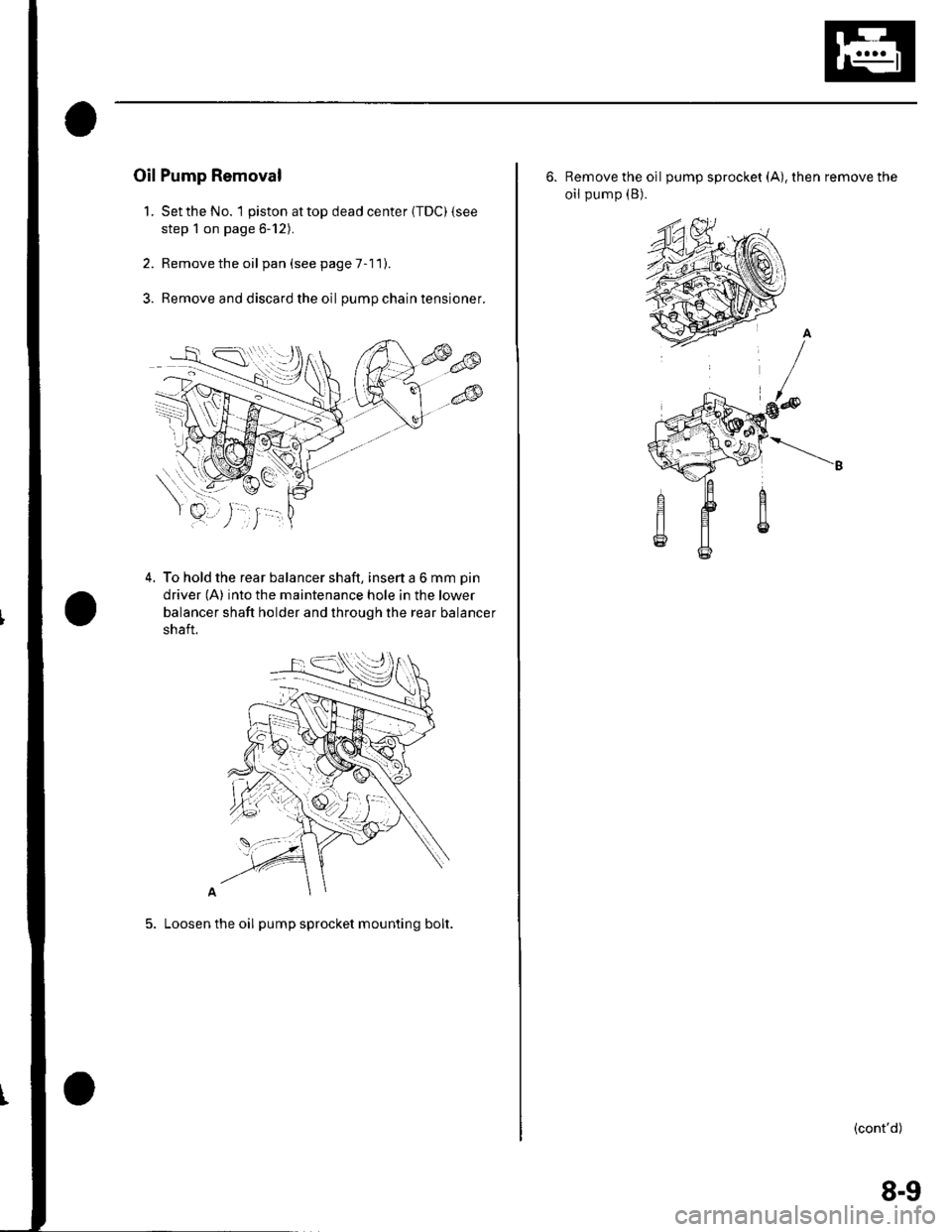
Oil Pump Removal
1. Setthe No. 1 piston attop dead center {TDC) {see
step 1 on page 6-12).
2. Remove the oil pan(seepageT-11).
3. Remove and discard the oil pumpchaintensioner.
4. To hold the rear balancer shaft, insert a 6 mm pin
driver (A) into the maintenance hole in the lower
balancer shaft holder and through the rear balancer
shaft.
5. Loosen the oil pump sprocket mounting bolt.
6. Remove the oil pump sprocket (A), then remove the
oil pump (B).
(cont'd)
8-9
Page 180 of 1139
Engine Lubrication
Oil Pump Overhaul (cont'd)
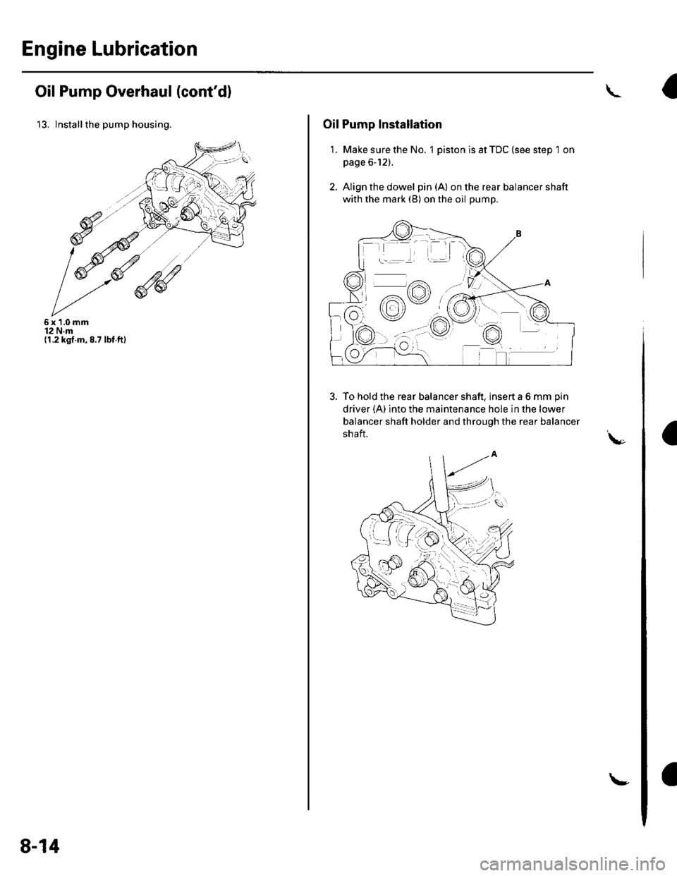
13. lnstallthe pump housing.
6x1,0mm12 N.m(1.2 kgt.m,8.7 lbf.ft)
8-14
!
Oil Pump Installation
1. Make sure the No. 1 piston is at TDC (see step 1 on
page 6-12).
2. Align the dowel pin{A} on the rear balancer shaft
with the mark (B) on the oil pump.
To hold the rear balancer shaft, insert a 6 mm pin
driver {A) into the maintenance hole in the lower
balancer shaft holder and through the rear balancer
shaft.\,-
9%ttrc
+:.:4.4 / t \
o/.-lY\
:aa:'
-rr
dv
f,o-;
Page 401 of 1139
Clutch
Clutch Pedal, Clutch
Adjustment
NOTE:. To check the clutch pedal position switch(see page 4-45).. To check the clutch interlock switch (see page 4-6).. Remove the driver's side floor mat before adjusting
the clutch pedal.. The clutch is self-adjusting to compensate for wear.. lf there is no clearance betweenthe mastercylinderpiston and push rod, the release bearing will be held
against the diaphragm spring. which can result in
clutch slippage or other clutch problems.
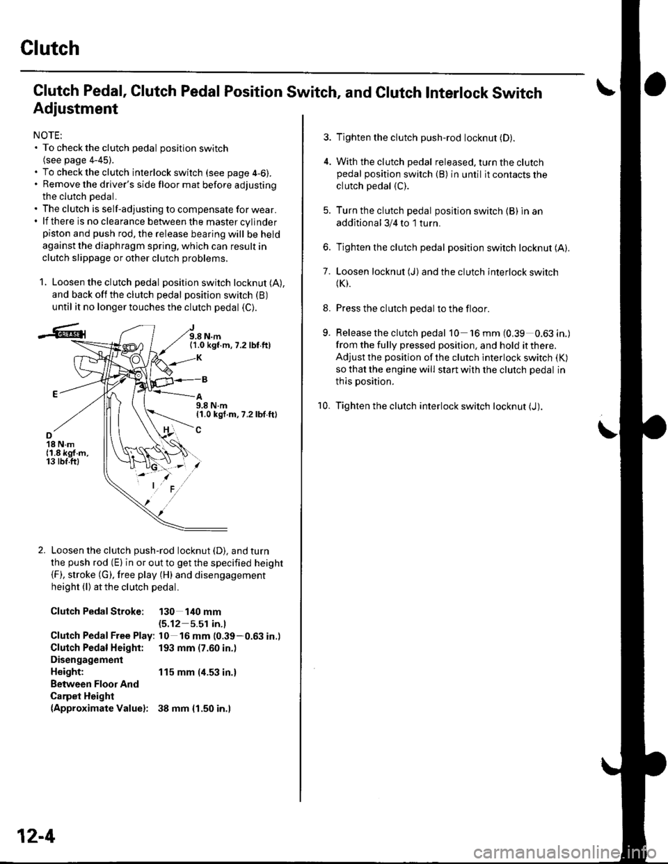
1. Loosen the clutch pedal position switch locknut (A),
and back off the clutch pedal position switch (B)
until it no longer touches the clutch pedal (C).
J9.8 N.m(1.0 kgf.m,7.2 lbf.ft)
A9.8 N.m11.0 kgf.m, 7.2 lbf.ft)
o18 N.m{1.8 kgf.m,13 tbf.ftl
Loosen the clutch push-rod locknut (D). and turn
the push rod (E) in or out to get the specified height(F), stroke (G). free play (H) and disengagement
height (l) atthe clutch pedal.
Clutch PedalStroke: 130 140 mm(5.12 5.51 in.l
Clutch Pedal Free Play: l0 16 mm (0.39-0.63 in.)
Clutch Pedal Height: 193 mm (7.60 in.)
Disengagement
Height: 115 mm (4.53 in.)
Between Floor And
Carpet Height(Approximate Valuel: 38 mm {1.50 in.l
12-4
Pedal Position Switch, and Clutch Interlock Switch
3. Tighten the clutch push-rod locknut (D).
4. With the clutch pedal released. turn the clutchpedal position switch (B) in until it contacts the
clutch pedal (C).
5. Turn the clutch pedal position switch {B) in an
additional 3/4 to 1 turn.
6. Tighten the clutch pedal position switch locknut (A).
7. Loosen locknut (J)and the clutch interlock switch(K).
8. Press the clutch pedal to the floor.
9. Release the clutch pedal 10 'l6mm(0,39 0.63in.)
from the fully pressed position, and hold it there.
Adjust the position of the clutch interlock switch (K)
so that the engine will start with the clutch pedal in
thls position.
10. Tighten the clutch interlock switch locknut (J).
Page 599 of 1139
Gonventional Brake Components
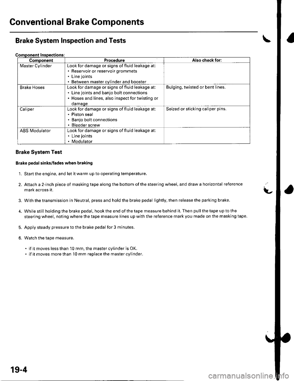
ComponentProcedureAlso check for:
l\4aster CylinderLook for damage or signs of fluid leakage at;. Reservoir or reservoir grommets
. Line joints
. Between master cvlinder and booster
Brake HosesLook for damage or signs of fluid leakage at:. Line joints and banjo bolt connections. Hoses and lines. also inspect for twisting or
damaqe
Bulging, twisted or bent lines.
CaliperLook for damage or signs of fluid leakage at:. Piston seal. Banjo bolt connections. Bleeder screw
Seized or sticking caliper pins.
ABS l\ilodulatorLook for damage or signs of fluid leakage at:. Line joints
. Modulator
Brake System Inspection and Tests
Brake System Test
Brake pedal sinks/fades when braking
1. Start the engine, and let it warm up to operating temperature.
2. Attach a 2-inch pieceof masking tape along the bottom of the steering wheel, and draw a horizontal reference
mark across it.
With the transmission in Neutral, press and hold the brake pedal lightly, then release the parking brake.
While still holding the brake pedal, hook the end of the tape measure behind it. Then pull the tape up to the
steering wheel, noting where the tape measure lines up with the reference mark you made on the masking tape.
Apply steady pressure to the brake pedal for 3 minutes.
Watch the tape measure.
. if it moves less than 10 mm, the master cylinder is OK.
. if it moves more than 10 mm replace the master cylinder.
t-
3.
5.
6.
19-4
Page 607 of 1139
Conventional Brake Gomponents
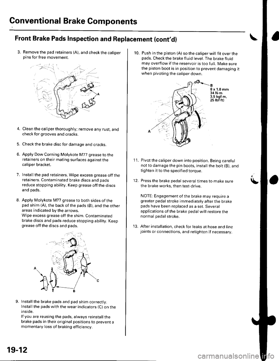
Front Brake Pads Inspection and Replacement (cont'dl
3. Remove the pad retainers (A), and check the caliperpins for free movement.
/:-."
t-... .,.';-iri.: '1=' r
.. a.-
4. Clean the caliper thoroughly; remove any rust, andcheck for grooves and cracks.
5. Checkthe brake disc for damage and cracks.
6. Apply Dow Corning Molykote M77 grease to theretainers on their mating surfaces against thecaliper bracket.
7. Installthe pad retainers. Wipe excess grease offtheretainers. Contaminated brake discs and pads
reduce stopping ability. Keep grease off the discsand pads.
8. Apply Molykote l\477 grease to both sides of thepad shim {A), the back ofthe pads (B), and the other
areas indicated by the arrows.
Wipe excess grease off the shim. Contaminated
brake discs and pads reduce stopping ability. Keepgrease off the discs and pads.
Installthe brake pads and pad shim correctly.Install the pads with the wear indicators (C) on theinside.
lf you are reusing the pads, always reinstall thebrake pads in their original positions to prevent amomentary loss of braking efficiency.
, a .).
19-12
10. Push in the piston (A) so the caliper will fitoverthepads. Check the brake fluid level. The brake fluid
may overflow if the reservoir is too full. lvlake surethe piston boot is in position to prevent damaging itwhen pivoting the caliper down
8x1.0mm34 N.m3.5 kgt m.25 tbf.ft)
11. Pivot the caliper down into position. Being carefulnot to damage the pin boots, install the bolt (B), and
tighten it to the specified torque.
12. Press the brake pedal several timestomakesure
the brake works, then test drive.
NOTE: Engagement of the brake may require agreater pedal stroke immediately after the brakepads have been replaced as a set. Several
applications of lhe brake pedal will restore thenormal pedal stroke.
13. After installation, check for leaks at hose and linejoants or connections, and retighten if necessary.
\
Page 609 of 1139
Conventional Brake Components
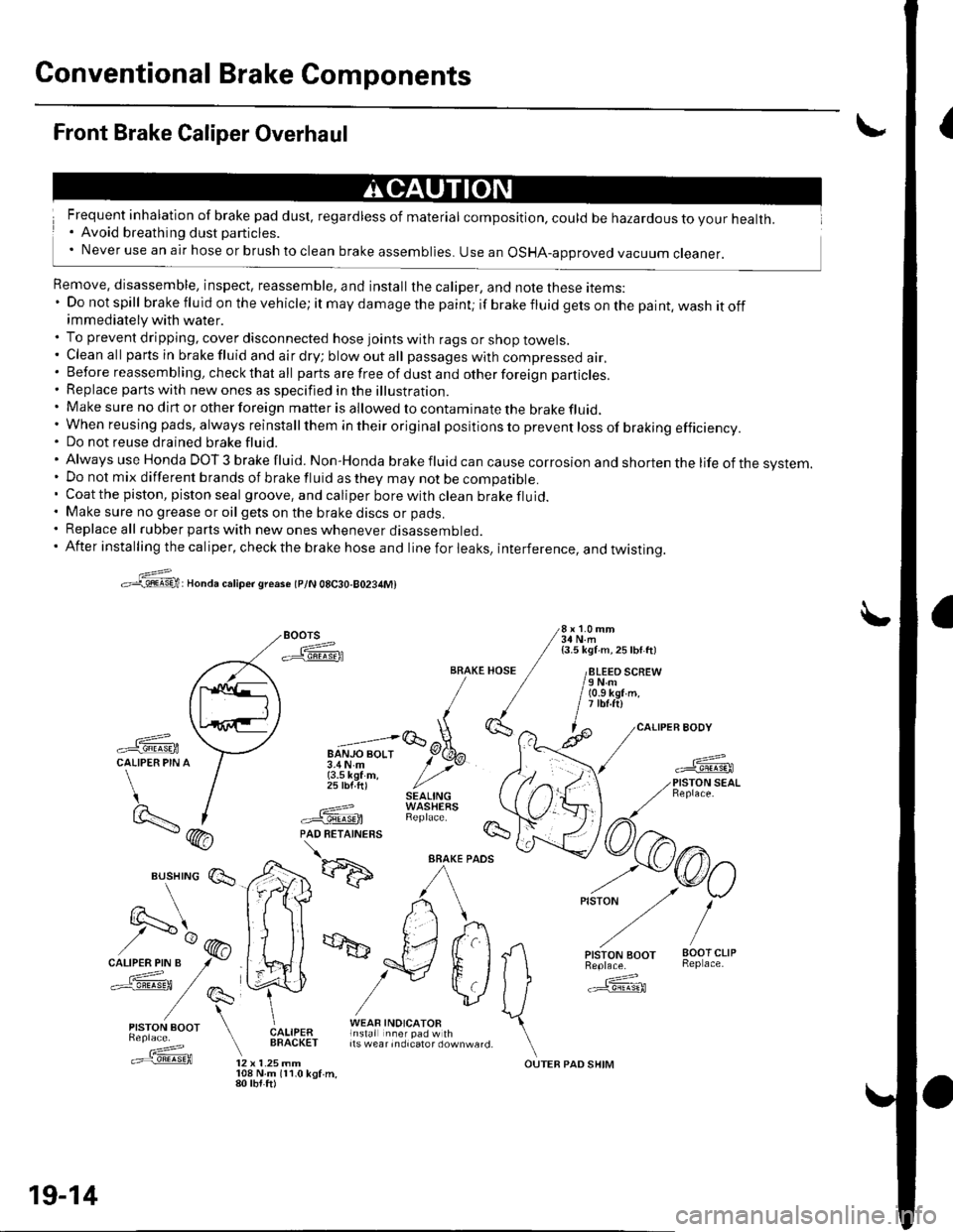
{Front Brake Caliper Overhaul
Frequent inhalation of brake pad dust, regardless of material composition, could be hazardous to your health.. Avoid breathing dust particles.' Never use an air hose or brush to clean brake assemblies. use an osHA-approved vacuum cleaner.
Remove, disassemble, inspect, reassemble, and install the caliper, and note these items:' Do not spill brake fluid on the vehicle; it may damage the paint; if brakefluidgetsonthepaint,washitoffimmediately with water.. To prevent dripping, cover disconnected hose joints with rags or shop towels.. Cleanall partsinbrakefluidandairdry;blowoutall passageswith compressed air.. Before reassembling, check that all parts are free of dust and other foreign particles.. Replace parts with new ones as specified in the illustration.. Make sure no dirt or other foreign matter is allowed to contaminate the brake fluid,' When reusing pads, always reinstallthem in their original pos itio ns to prevent loss of braking efficiency.. Do not reuse drained brake fluid.'AlwaysuseHondaDOT3brakefluid.Non'Hondabrakefluidcancausecorrosionandshortenthelifeofthesvstem.
. Do not mix different brands of brake fluid as they may not be compatible.. Coatthe piston, piston seal groove, and caliper borewithclean brakefluid.. Make sure no grease or oil gets on the brake discs or pads.. Replace all rubber parts with new ones whenever disassembled.. After installing the caliper, check the brake hose and line for leaks, interference, and twistinq.
>:@:Honda caliper sreaso tplN 08C30-80234M)
Boors 3i,l'1.'"
-ffiFA / isli\ii ^ zsw ttt
/paq\tl ll /
,\L,.'iE/ [
-ffi \--l u";;;lqEtCALIPER PIN A / 3.4N.m y' >vr / {3.5 kef m, / ,,' / 25 lbf ft) //'t / SEAL|NG)- I ---=-? WASHEaS
BRAKE HOSE / /8LEEO SCREW/ / /eNm/ / / (o.s kgr'm./ / | itbt.ftl,1(}', ^ l^ /caLl
-ffi \:7 "=;lGoX-
*fL-f
/) I .===? WAStrtXS \t9..- | #.'@ RepracF /7\- (hA PAD RETATNERS !s- / \
*d':ffi
^/rkr) ,-o/
vlJ ffi
Es,lry:' E*,e,a ["fif:i#l1t*"_,,. \.==f@ tz x t.zsmm ourEB paD sHrM
19-14
108 N.m 111.0 kgf.m,80 tbt.ft)
Page 611 of 1139
Conventional Brake Components
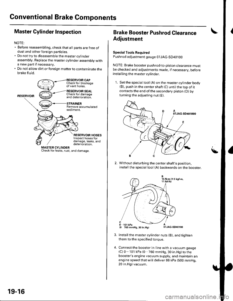
Master Cylinder Inspection
NOTE:. Before reassembling, check that al I parts are f ree ofdust and other foreign particles.. Do nottryto disassemblethe mastercylinder
assembly. Replace the master cylinder assembly witha new part if necessary.. Do not allow dirt or foreign matter to contaminate thebrake fluid.
RESERVOIB CAPI unecK Ior otocKageof vent holes.
RESERVOIR
,--l RESERvOIR SEALCheck lor damaoe
RESERVOIR HOSESInspect hoses fordamage, leaks, anddeterioration.
r',,.J\+
v
MASTER CYLINDERCheck for leaks, rust, and damage
and deterioration.
STRAINERRemove accumulatedseotment.
19-16
Brake Booster Pushrod Clearance
Adjustment
SpecialTools Required
Pushrod adjustment gauge 07JAG-SD40100
NOTE: Brake booster pushrod-to-piston clearance mustbe checked and adjustments made, if necessarV, beforeinstalling the master cylinder.
1. Setthespecial tool (A) onthe mastercylinder bodv(B), push in the center shaft (C) until the top of itcontacts the end of the secondary piston {D) byturning the adjusting nut (E).
Without disturbing the center shaft's position,
installthe specialtool (A) backwards on the booster.
Install the master cylinder nuts (B), and tighten
them to the specified torque.
Connecl the booster in line with a vacuum gauge
{C) 0-101 kPa {0'-760 mmHg, 30 in.Hg) to thebooster's engine vacuum supply, and maintain anengine speed that will deliver 66 kPa (500 mmHg,20 in.Hg) vacuum.
15 N m {r.511 tbf.ftl
Page 612 of 1139
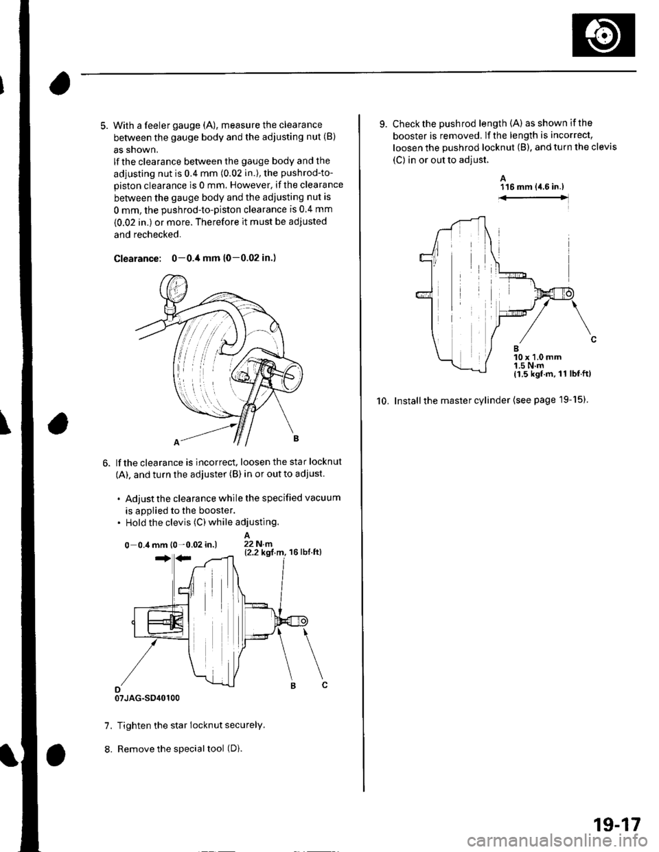
5. With a feeler gauge (A), measure the clearance
between the gauge body and the adjusting nut (B)
as snown,
lf the clearance between the gauge body and the
adjusting nut is 0.4 mm (0.02 in.), the pushrod-to-
piston clearance is 0 mm. However. if the clearance
between the gauge body and the adjusting nut is
0 mm, the pushrod-to-piston clearance is 0 4 mm
{0.02 in.) or more. Therefore it must be adjusted
and rechecked.
Clearance: 0-0./t mm (0-0.02 in.)
lf the clearance is incorrect, loosen the star locknut
(A). and turn the adjuster (B) in or out to adjust.
. Adjust the clearance while the specified vacuum
is appiied to the booster.. Hold the clevis (C) while adjusting.
A0 0.4 mm l0 -0.02 in.) 22N.n
07JAG-SO40100
7. Tighten the star locknut securely.
8. Remove the special tool (D).
9. Check the pushrod length (A) asshownifthe
booster is removed, lf the length is incorrect,
loosen the pushrod locknut (B), and turn the clevis
(C) in or out to adjust.
A116 mm {4.6 in.)
10. Installthe master cylinder (see page l9-15)
10 x 1.0 mm1.5 N'm11.5 kgf.m,11 lbf.ftl
19-17
Page 616 of 1139
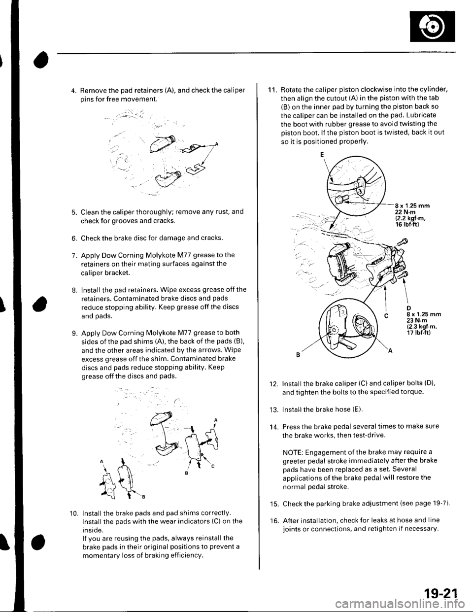
4. Remove the pad retainers (A). and check the caliper
pins for free movement.
:.i _ _l
7.
8.
5. Clean the caliper thoroughly; remove any rust. and
check for grooves and cracks.
6, Check the brake disc for damage and cracks.
Apply Dow Corning Molykote M77 grease to the
retainers on their mating surfaces against the
caliper bracket,
Installthe pad retainers. Wipe excess grease offthe
retainers. Contaminated brake discs and pads
reduce stopping ability. Keep grease off the discs
and pads.
Apply Dow Corning Molykote lvl77 grease to both
sides of the pad shims {A), the back of the pads (B),
and the other areas indicated by the arrows. Wipe
excess grease off the shim. Contaminated brake
discs and pads reduce stopping ability. Keep
grease off the discs and pads.
9.
..-.
10. Installthe brake pads and pad shims correctly.
Installthe pads wirh the wear indicators {C) on the
inside.
lf you are reusing the pads, always reinstall the
brake pads in their original positions to prevent a
momentary loss of braking efficiency.
11. Rotate the caliper piston clockwise into the cylinder,
then align the cutout (A) in the piston with the tab
{B) on the inner pad by turning the piston back so
the caliper can be installed on the pad. Lubricate
the boot with rubber grease to avoid twisting the
Diston boot. lf the piston boot is twisted, back it out
so it is positioned properly.
8 x 1.25 mm22 N.ml2.2 kgt m,16 rbl.ttl
.ar
D8 x 1.25 mm23Nm{2.3 kgf.m,17 rbf.ft)
13.
14.
Installthe brake caliper (C) and caliper bolts (D).
and tighten the bolts to the specified torque.
Installthe brake hose (E).
Press the brake pedal several times to make sure
the brake works, then test-drive.
NOTE: Engagement of the brake may require a
greeter pedal stroke immediately after the brake
pads have been replaced as a set. Several
applications of the brake pedal will restore the
normal pedal stroke,
15. Check the parking brake adjustment {see page 19-7).
16. After installation, check for leaks at hose and line
joints or connections, and retighten if necessarY.
19-21
Page 618 of 1139
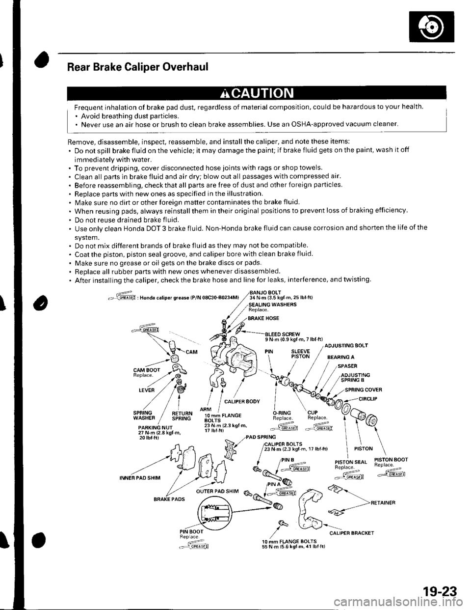
Rear Brake Caliper Overhaul
Frequent inhalation of brake pad dust, regardless of material composition, could be hazardous to your health.
' Avoid breathing dust particles.
. Never use an air hose or brush to clean brake assemblies. Use an OSHA-approved vacuum cleaner'
Remove, disassemble, inspect, reassemble, and installthe caliper, and note these items:
. Donotspill brake fluid on the vehicle; it may damage the paint; if brake f luid gets on the paint, wash it off
immediately with water.. To prevent dripping. cover disconnected hose joints with rags or shop towels.
. Cleanall partsinbrakefluidandairdry;blowoutall passageswith compressed air'
. Before reassembling, check that all parts are free of dust and other foreign particles
. Replace pans with new ones as specified in the illustration.. Make sure no dirt or other foreign matter contaminates the brake fluid.
. When reusing pads, always reinstallthem in their original positions to prevent loss of b ra king efficie ncy.
. Do not reuse drained brake fluid.
. Use only clean Honda DOT 3 brake fluid. Non-Honda brake fluid can cause corrosion and shorten the life of the
system.. Do not mix different brands ot brake fluid as they may not be compatible.
. Coatthe piston, piston seal groove, and caliper bore with clean brake fluid.
. Make sure no grease or oil gets on the brake discs or pads.
. Replaceall rubber parts with new ones whenever disassembled.
. After installing the caliper, check the brake hose and line for leaks, interference. and twisting.
oG , nonau."rip6r qreas€ lP/N 08c30-aoa4Ml34 N.m (3.5 kgf m,25lbtft)BOLT
WASHERS
BRAKE HOSE
a
l,i,,'IltE" / !!;,ff
olT-J,.o"c.O.RING CUPBeplace. Beplace.
.ARKING NUr lii.'i rz.r rgr.. Gd ffi27Nm{2.8kgtm,
\-"o, V((rA ",1 ;[.,.JF /;;;;---
t H\a \l / t,i*t'*"
?,,.t/*"^.,,.:,"", /"V4#
ADJUSTING BOLT
,/
27Nm{2.8kgf.m,20 tbf.ftr PAD SPRING
A,n Na 7lfl,lif,loffi ',,0,n, ,,:,o" \
--t)(*ff l^7k ''"'t!1'ry#'
INNEBPA'SHIM
/ .r.:._U i*E'( ":;*" *dF ,.2>a>-
fr.x{_>@ fftt **-->**^'"
,,.-"iV ,/q &'"o.,"."""o"^.,
: 10 MM FLANGE BOLTS.:r=,9!q!q}l 55 N m (5.6 lgf-m, 4r lbt ft)
19-23