Indicator HONDA CIVIC 2003 7.G Owners Manual
[x] Cancel search | Manufacturer: HONDA, Model Year: 2003, Model line: CIVIC, Model: HONDA CIVIC 2003 7.GPages: 1139, PDF Size: 28.19 MB
Page 1020 of 1139
sRs
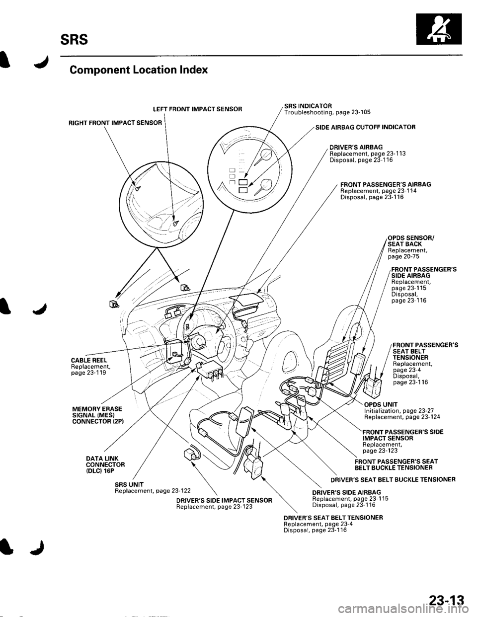
Component Location Index
LEFT FRONT IMPACT SENSOB
RIGHT FRONT IMPACT SENSOR
CABLE REELBeplacement,page 23-119
SIDE AIRBAG CUTOFF INDICATOR
DRIVER'S AIRBAGReplacement, page 23-1 13Disposal, page 23 1'16
SRS INOICATORTroubleshooting, page 23-105
FRONT PASSENGER'S AIRBAGReplacement, page 23-1 14Disposal, page 23'116
SENSOR/SEAT BACKReplacement,page 20-75
FRONT PASSENGER'SSIDE AIRBAGReplacement,page 23'1'15Disposal,page 23'116
FRONT PASSENGER'SSEAT BELTTENSIONERBeplacement,page 23-4Disposal,page 23-'116
MEMORY ERASESIGNAL (MES}CONNECTOR I2PI
DATA LINKCONNECTOR(DLCI 16P
OPDS UNITInitialization, page 23-27Replacement, page 23-124
PASSENGER'S SIOEIMPACT SENSORReplacement,page 23-123
FRONT PASSENGER'S SEATBELT BUCKLE TENSIONER
DRIVER'S SEAT BELT TENSIONERReplacement, page 23 4Disposal, page 23-116
23-13
Page 1030 of 1139
General Troubleshooting Information
DTC (Diagnostic Trouble Codesl
The self-diagnostic function of the SRS system allows it
to locate the causes of system problems and then store
this information in memory. For easier troubleshooting,
this data can be retrieved via a data link circuit.
. When you turn the ignition switch ON (ll), the SRS
indicator will come on. lf it goes off after 6 seconds,
the system is normal.. lf there is an abnormality, the svstem locates and
defines the problem, stores this information in
memory, and turns the SRS indicator on. The data
will remain in the memory even when the ignition
switch is turned off or if the battery is disconnected.. When you connect the Honda PG lM Tester to the 16P
data link connector (DLC)to short the SCS terminal,
and turn the ignition switch ON (ll). the SRS indicator
will indicate the diagnostic trouble code (DTC) by the
number of blinks.. When you connect the Honda PGM Tester to the 16P
data link Connector (DLC), you can retrieve the DTC in
the Honda Systems "SRS" menu.. After reading and recording the DTC, proceed with
the troubleshooting procedure for th is code.
Precautions. Use only a digital multimeter to check the system. lf
it's not a Honda multimeter, make sure its output is
10 mA (0.01A) or less when switched to the smallest
value in the ohmmeter range, A tester with a higher
output could damage the airbag circuit or cause
accidental airbag deployment and possible injury.. Whenever the ignition switch is ON (ll), or has been
turned OFF for less than 3 minutes, be careful not to
bump the SRS uniU the airbags could accidentally
deploy and cause damage or injuries.. Before you remove the SRS harness, disconnect the
driver's airbag connector. the front passenger's
airbag connector, both side airbag connectors, both
seat belt buckle tensioner connectors, and both seat
belt tensioner connectors.. Make sure the battery is sufficiently charged. lf the
battery is dead or low, measuring values won't be
correct.. Do not touch a tester probe to the terminals in the
SRS unit or harness connectors, and do not connect
the terminals with a jumper wire. Use only the
backprobe set and the Honda PGM Tester. Backprobe
spring loaded lock type connectors correctly.
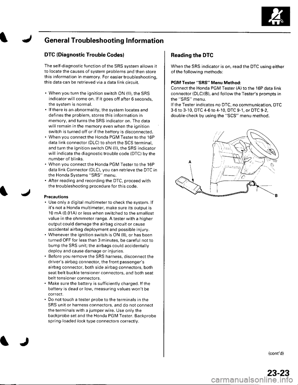
Reading the DTC
When the SRS indicator is on, read the DTC using either
of the following methods:
PGM Tester "SRS" Menu Method:
Connect the Honda PGM Tester {A) to the 16P data link
connector {DLC)(B), and follow the Tester's Drompts in
the "SRS" menu.
lf the Tester indicates no DTC, no communication. DTC
3-6 to 3-'10, DTC 4-6 to 4-10, DTC 9-1, or DTC 9-2,
double-check by using the "SCS" menu method.
(cont'd)
23-23
Page 1031 of 1139
sRs
General Troubleshooting Information (cont'd)
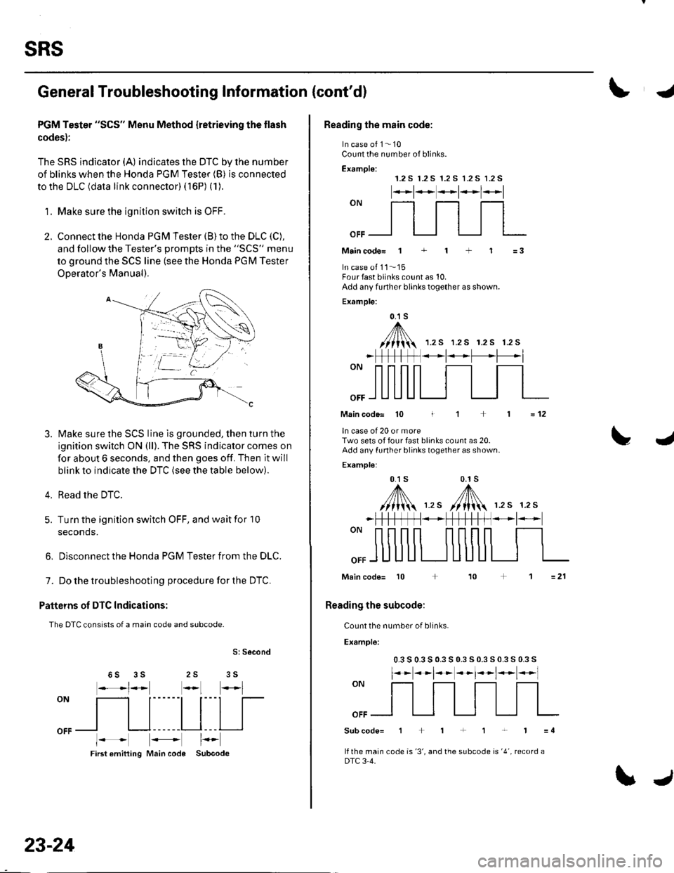
PGM Tester "SCS" Menu Method {retrieving the flash
codes):
The SRS indicator (A) indicates the DTC by lhe number
of blinks when the Honda PGM Tester (B) is connected
to the DLC (data link connector) ( 16P) (1).
'1. Make sure the ionition switch is OFF.
2. Connect the Honda PGN4 Tester (B) to the DLC (C),
and follow the Tester's oromDts in the "SCS" menu
to ground the SCS line (see the Honda PGM Tester
ODerator's Manual).
Make sure the SCS line is grounded, then turn the
ignition switch ON (ll). The SRS indicator comes on
for about 6 seconds, and then goes off. Then it will
blink to indicate the DTC (see the table below).
Read the DTC.
Turn the ignition switch OFF, and wait for 10
seconds.
3.
4.
5.
6, Disconnect the Honda PGM Tester from the DLC.
7. Do the troubleshooting procedure for the DTC.
Patteins of DTC Indications:
The DTC consists of a main code and subcode.
S: Second
25 356S
oN
[ltl|[
oFFl I l------Ll---l I
First emitting Main code Subcode
23-24
\J
Reading the main code:
In case of 1- 10Count the number of blinks.
Examplo:1.2 S r.2 S 1.2 S 1.2 S 1.2 S
*t**t*l*l
""_f]_flfl
Maincodo= 1 + 1 + 1 =3
In case ot 11..'15Four fast blinks count as 10.Add any funher blinks together as shown.
Example:
0.1 s
,A/// t\\//lii 1.rs r.2s r.2s 1.2s
_ | *t* -L'--*l
Main code= 10 I
ln case of 20 or moreTwo sets of four fast blinks count as 20.Add any funher blinks together as shown.
Examplo:
0.1 s 0.1s
,y'fl\,,. /[N 12s 12s
=12
L4
""ffi
*FtftffN*+fH-t-ff *l-
Main code= 10 + 10
Reading the subcode:
Count the number of blinks.
Example:
0.3 s 0.3 s 0.3 s 0.3 s 0.3 s 0.3 s 0.3 s
l**t**t*t*t*l
""ffi
Subcode=1+1+1r'1=4
lf the main code is '3', and the subcode is '4', record aDTC 3 4.
Page 1032 of 1139
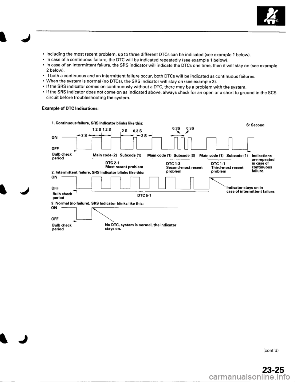
Including the most recent problem, up to three different DTCS can be indicated (see example 1 below).ln case of a continuous failure, the DTC will be indicated repeatedly {see example 1 below).In case of an intermittent failure, the SRS indicator will indicate the DTCS one time, then it will stay on (see example2 below).
lf both a continuous and an intermittent failure occur, both DTCS will be indicated as continuous failures.When the system is normal (no DTCS), the SRS indicator will stay on (see example 3).lf the SRS indicator comes on continuously without a DTC, there mav be a problem with the svstem.lf the SRS indicator does not come on as indicated above, always check for an open or a short to ground in the SCScircuit before troubleshooting the system.
Example of DTC Indications:
1. Continuous failure, SRS Indic6tor blink$ like this:
1.2 S 1,2 SS: Second0.3s 0.3s
ON
OFF
Bulb checkperiodMain code (21 Subcode l1)
DTC 2-lMost recent p.oblem
2. Intermittent failure, SRS lndicator blinks like this:ON
Main code l1lSubcode (3) Main code {11 Subcode {'l)Indicationsare lepeatedtn cese otcontinuousfailure.
lndicator stays on incase of i nterm ittent failu re.
(cont'd)
DTC 1-3DTC 1-1Sscond-mostrecent Third-mostrocentproblem problem
OFF
Bulb checkperiodDTC 5-1
3. Normal (no failure|, SRS Indicator blinks like this:ON
OFF
Bulb chockperiodNo DTC, systom is normal, the indicatorstays on.
0.3 s
23-25
Page 1033 of 1139
sRs
General Troubleshooting Information (cont'dl
Erasing the DTG Memory
Specisl Tool Required
SCS service connector 07PAz-0010100
To erase the DTC(S)from the SRS unit, use a Honda
PGM Tester {see lhe Honda PGfM Tester SRS Vehicle
System Supplement) or the following procedure.
1. Make sure the ignition switch is OFF.
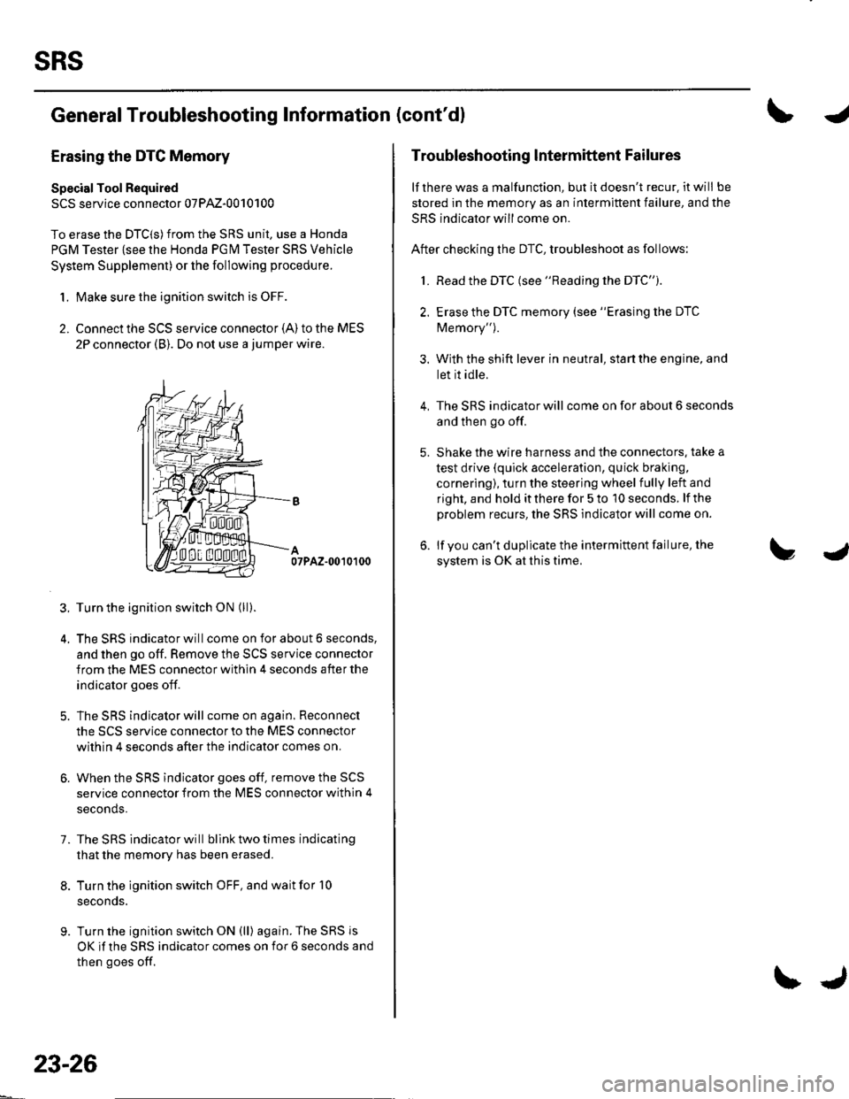
2. Connect the SCS service connector {A) to the MES
2P connector (B). Do not use a jumper wire.
07PAZ-0010100
3. Turn the ignition switch ON (ll).
4. The SRS indicator will come on for about 6 seconds,
and then go off. Remove the SCS service connector
from the MES connector within 4 seconds after the
indicator goes off.
5. The SRS indicator will come on again. Reconnect
the SCS service connector to the MES connector
within 4 seconds after the indicator comes on.
6. When the SRS indicator goes off, remove the SCS
service connector from the MES connector within 4
seconds.
7. The SRS indicator will bllnk two times indicating
that the memory has been erased.
8. Turn the ignition switch OFF, and wait for '10
seconds.
9. Turn the ignition switch ON (ll) again. The SRS js
OK if the SRS indicator comes on for 6 seconds and
then goes off.
23-26
\J
Troubleshooting lntermittent Failures
lf there was a malfunction, but it doesn't recur. it will be
stored in the memory as an intermittent failure, and the
SRS indicator will come on.
After checking the DTC, troubleshoot as follows:
1. Read the DTC (see "Reading the DTC").
2. Erase the DTC memory (see "Erasing the DTC
Memory").
3. With the shift lever in neutral, start the engine, and
let it idle.
The SRS indicator will come on for about 6 seconds
and then go off.
Shake the wire harness and the connectors. take a
test drive (quick acceleration, quick braking,
cornering), turn the steering wheel fully left and
right, and hold it there for 5 to '10 seconds. lf the
problem recurs, the SRS indicator will come on.
lf you can't duplicate the intermittent failure, the
system is OK at this time.
4.
Page 1034 of 1139
I
Initializing the OPDS {Occupant Position Detection System} Unit
Special Tool Required
SCS service connector 07PAz-00'1 01 00
When a seat-back cover, seat-back cushion, and/or OPDS unit is replaced, initialize the OPDS by following theprocedure below.
NOTE: Make sure the front passenger's seat is dry. Set the seat-back in the normal position, and make sure there isnothing on the seat.
'1. l\4ake sure the ignition switch is OFF.
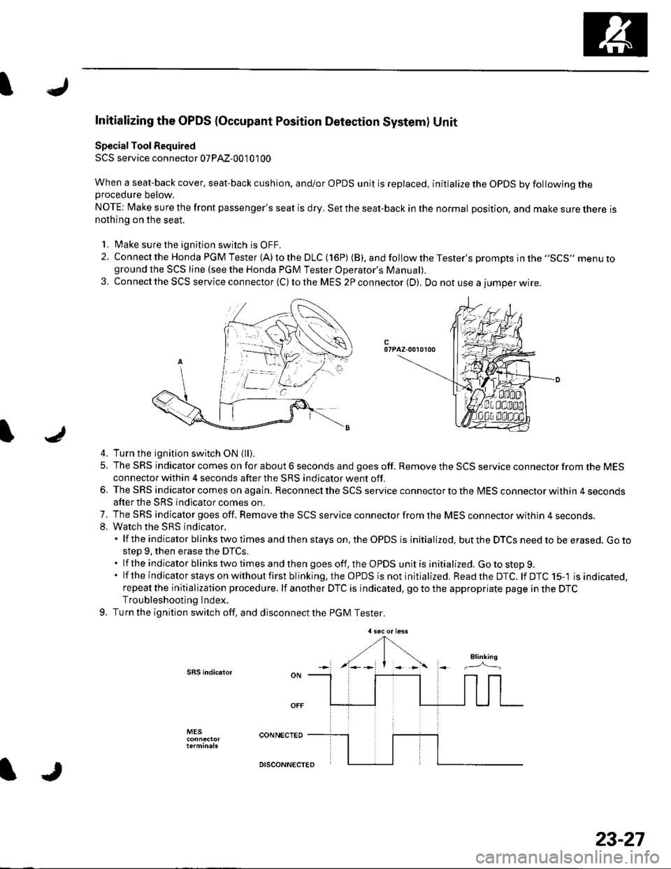
2. Connect the Honda PGM Tester (A) to the DLC (16P) (B), andfollowtheTester's prompts jn the ,,SCS,, menu toground the SCS line (see the Honda PGM Tester Operator's ManuaD.
3. Connect the SCS service connector (C) to the MES 2P connector (D). Do not use a iumoer wire.
c07PAZ-00r0100
4. Turn the ignition switch ON {ll).
5. The SRS indicator comes on for about 6 seconds and goes off. Remove the SCS service connector from the MESconnector within 4 seconds after the SRS indicator went off.
6. The SRS indicator comes on again. Reconnect the SCS service connector to the MES connector within 4 secondsafter the SRS indicator comes on.
7. The SRS indicator goes off. Remove the SCS service connector from the MES connector withln 4 seconds.8. Watch the sRS indicator.'lftheindicatorblinkstwotimesandthenstayson,theOPDSisinitialized.buttheDTCSneedtobeerased.Goto
step 9, then erase the DTCS..lftheindicatorblinkstwotimesandthengoesoff,theOPDSunitisinitialized.Gotostep9.
' lf the indicator stays on without first blinking.the OPDS is not initialized. Readthe DTC. lf DTC 15-'l is indicated,repeat the initialization procedure. lf another DTC is indicated, go to the appropriate page in the DTCTroubleshooting Index.
9. Turn the ignition switch off, and disconnect the PGM Tester.
SBS indic.ror
MES
IJ
DISCONNECTED
23-27
Page 1036 of 1139
IJ
lr
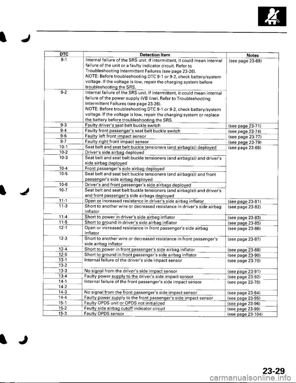
DTCDetection ltemNotes9-1Internal failure of the SRS unit. lf intermittent, it could mean internalfailure of the unit or a faulty indicator circuit. Refer toTroubleshooting Intermittent Failures (see page 23-26).
NOTE: Before troubleshooting DTC 9-1 or 9-2, check battery/systemvoltage. lf the voltage is low, repair the charging system beforetroubleshooting the SRS.
(see page 23-69)
9-2Internal failure of the SRS unit. lf intermittent, it could mean internalfailu re of the power supply (VB line). Refer to TroubleshootingIntermittent Failures (see page 23-26).
NOTE: Before troubleshooting DTC 9-1 or 9-2, check battery/systemvoltage. lf the voltage is low, repair the charging system or replacethe b€ttery before troubleshooting the SRS.
9-3Faulty driver's seat belt buckle switch(see Daqe 23-71)9-4
9-6
FaultLtglt passenger's seat belt buckle switch
Faulty Ieft front imDact sensorlgqgfage 23-74)
{see Daqe 23-77)9-7Faulty right front impact sensor(see paqe 23-79)10-1Seat belt and seat belt buckle tensioners (and airbag(s)) deployedDriver's side airbag deployed
Seat belt and seat belt buckle tensioners (and airbag(s)) and driver'sside airbag deployed
Front passenqer's side airbao deDloved
(see page 23-69)10-2
r0-3
'10-4
'10-5Seat belt and seat belt buckle tensioners (and airbag(s)) and frontpassenqer's side airbaq deDloved
10-6Driver's and front passenqer's side al10-7Seat belt and seat belt buckle tensioners (and airbag(s)) and driver'sand front passenger's side airbags deployed
1 1-1Open or increased resistance in driver's side airbao inflator(see paqe 23-81)Short to another wire or decreased resistance in driver's side airbaoinflator
(see page 23-82)
11-4Short to power in driver's side airbaq inflator(see oaqe 23-83)I t-5Short to ground in driver's side airbaq inflator{see paqe 23-85)Open or increased resistance in front passenger's side airbaginflator
(see page 23-86)
Short to another wire or decreased resistance in front passenger's
side airbag inflator
(see page 23-87)
12-4Short to power in front passenqer's side airbaq inflator{see Daqe zJ-uu}I z-5Short to ground in front passenger's side airbaq inflator(see oaqe 23-90)13-1Internal failure of the driver's side impact sensor(see page 23-70)
No signal from the driver's side impact sensor(see paqe 23-91)13-4
14-1-7ii,
Faulty power supply to the df,rglllug t Opact s9I99LInternal failure ofthe front passenger's side impact sensor
(see page 23-92)(see page 23-70)
14-3No signal from the front passenger's side impact sensor(see paqe 23-94)14-4Faulty power supply to the front passenqer's side impact sensor(see page 23-95)15-1Faultv OPDS unit or OPDS not initialized(see paqe 23-96115-2Faulty side airbag cutoff indicator circuit(see Daqe 23-99)15-3Faulty OPDS sensor(see oaoe 23-104)
IJ
23-29
Page 1037 of 1139
SRS
SymptomDiagnostic procedureAlso check for
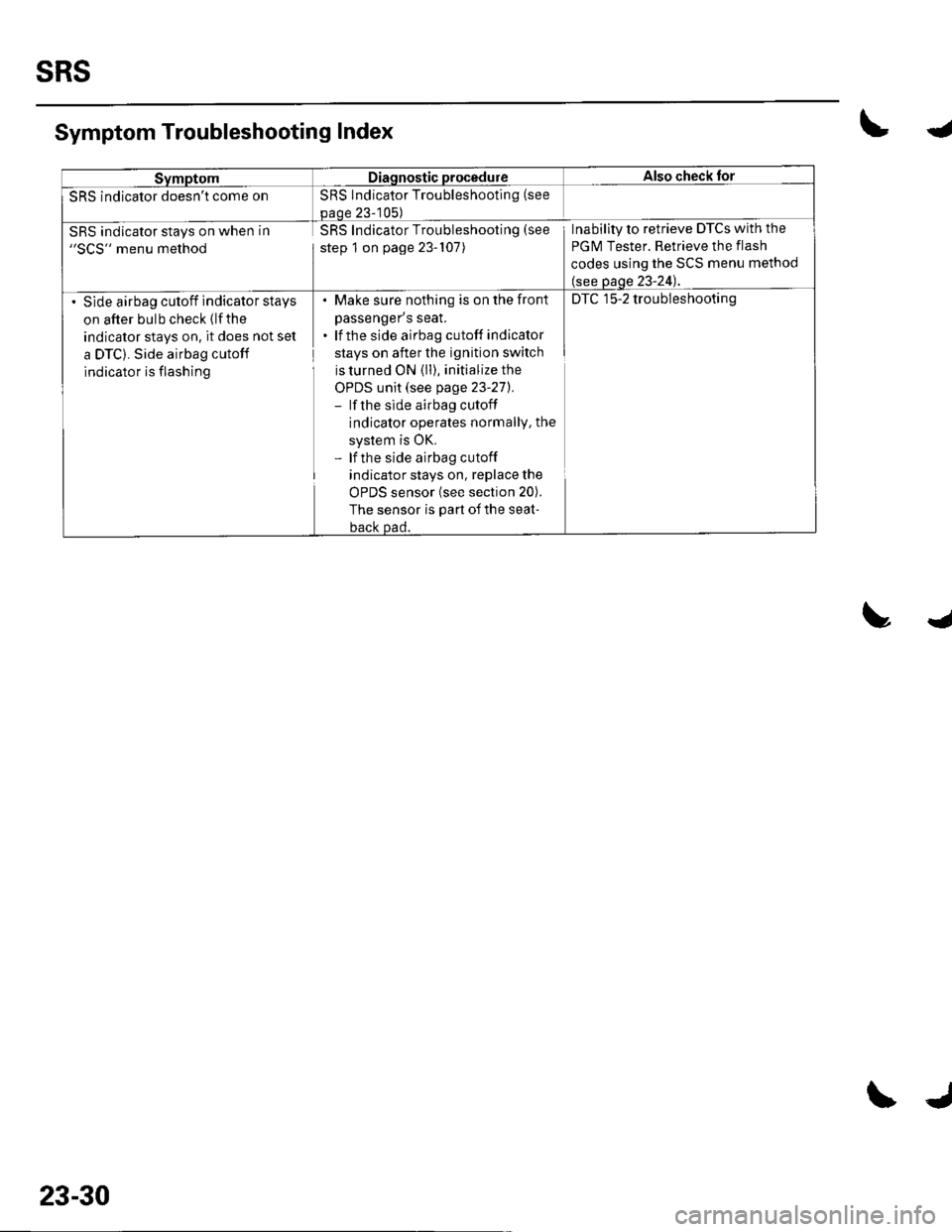
SRS indicator doesn't come onSRS Indicator Troubleshooting (see
paoe 23-105)
SRS indicator stays on when in"SCS" menu method
SRS Indicator Troubleshooting (see
step 1 on page 23-107)
Inability to retrieve DTCs with the
PGM Tester. Retrieve the flash
codes using the SCS menu method
(see page 23-24).
Slde airbag cutoff indicator stays
on after bulb check (lfthe
indicator stays on, it does not set
a DTC). Side airbag cutoff
indicator is flashing
. Make sure nothing is on the fronl
passenger's seat.. lf the side airbag cutoff indicator
stays on after the ignition switch
is turned ON (ll), initialize the
OPDS unit (see page 23-271.- lf the side airbag cutoff
indicator operates normallY, the
system is OK.- lf the side airbag cutoff
indicator stays on, replace the
uFU5 SenSOr {See SeCrOn ZUl.
The sensor is part of the seat-
back Dad.
DTC 15-2 troubleshooting
Symptom Troubleshooting Index\4
trJ
23-30
\J
Page 1038 of 1139
ISystem Description
SRS Components
Airbags
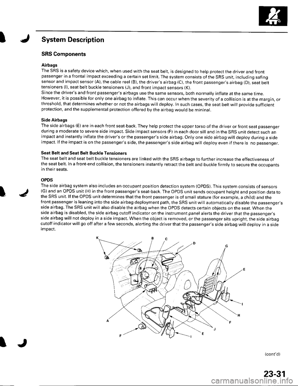
The SRS is a safety device which, when used with the seat belt, is designed to help protect the driver and frontpassenger in a frontal impact exceeding a certain set limit. The system consists ofthe SRS unit, including safingsensor and impact sensor (A), the cable reel (B), the driver's airbag (C), the front passenger,s airbag (D). seat belttensioners (l), seat belt buckle tensioners (J), and front impact sensors (K).
Since the driver's and front passenger's airbags use the same sensors, both normally inflate at the same ttme.However, it is possible for only one airbag to inflate. This can occur when the severity of a collision is at the margin, orthreshold, that determines whether or not the airbags will deploy. In such cases, the seat belt will provide sufficientprotection, and the supplemental protection offered by the airbag would be mininal.
Side Airbags
The side airbags (E) are in each front seat-back. They help protect the upper torso of the driver or front seat passenger
during a moderate to severe side impact. Side impact sensors (F) in each door sill and in the SRS unit detect such animpact and instantly inflate the driver's or the passenger's side airbag. Only one side airbag will deploy during a sideimpacl. lf the impact is on the passenger's side, the passenger's side airbag will deploy even if there is no passenger.
Seat Belt and Seat Belt Buckle Tensioners
The seat belt and seat belt buckle tensioners are linked with the SRS airbags to further increase the effectiveness ofthe seat belt. ln a front-end collision, the tensioners instantly retract the belt and buckle firmly to secure the occupantsin their seats.
OPDS
The side airbag system also includes an occupant position detection system (OpDS). This system consists of sensors(G)and an OPDS unit (H) in the front passenger's seat-back. The OPDS unit sends occupant heighl and position data tothe SRS unit. lf the OPDS unit determines that the front passenger is of small stature (for example, a child) and thefront passenger is leaning into the side airbag deployment path, the SRS unit will automatically disable the passenger'sside airbag. The SRS unit will also disable the airbag when the OPDS detects certain obiects on the seat. When theside airbag is disabled, the side airbag cutoff indicator on the instrument panel alerts the driver that the passenger'sside airbag will not deploy in a side impact. When the object is removed, or the passenger sits upright, the side airbagcutoff indicator will go off after a few seconds, alerting the driver that the passenger's side airbag will deploy in a sideimDact.
(cont'd)
I
23-31
Page 1040 of 1139
Self-diagnosis System
A self-diagnosis circuit is built into the SRS uniU when the ignition switch is turned ON (ll), the SRS indicator comes onand goes off after about 6 seconds if the SRS is operating normally.
lf the indicator does not come on, or does not go off after 6 seconds. or if il comes on while driving, it indicates anabnormality in the SRS. The SRS must be inspected and repaired as soon as possible.
For better serviceability, the SRS unit memory stores a DTC that relates to the cause of the malfunction, and the unit isconnected to the data link circuit. This information can be read with the Honda PGM Tester when it is connected to thedata link connector (DLc) (see page 23-23).
23-33