Start HONDA CIVIC 2003 7.G Workshop Manual
[x] Cancel search | Manufacturer: HONDA, Model Year: 2003, Model line: CIVIC, Model: HONDA CIVIC 2003 7.GPages: 1139, PDF Size: 28.19 MB
Page 626 of 1139
ABS Components
General Troubleshooting Information (cont'd)
How to Troubleshoot ABS DTCs
The troubleshooting flowchart procedures assume that
the cause of the oroblem is still Dresent and the ABS
indicator is still on. Following the flowchart when the
ABS indicator does not come on can result in incorrect
diagnosis.
The connector illustrations show the female terminal
connectors with a single outline and the male terminal
connectors with a double outline.
1. Ouestion the customer about the conditions when
the problem occured, and try to reproduce the
same conditions for troubleshooting. Find out
when the ABS indicator came on, such as during
ABS control, after ABS control, when the vehicle
was at a certain speed, etc.
2. When the ABS indicator does not come on during
the test-drive, but troubleshooting is done based on
the DTC, check for loose connectors. poor terminal
contact, etc., before you start troubleshooting.
3. After troubleshooting, clear the DTC,disconnect the
Honda PGM Tester. and test-drive the vehicle.
Make sure the ABS indicator does not come on.
How to Retrieve ABS DTCs
Honda PGM Tester Method:
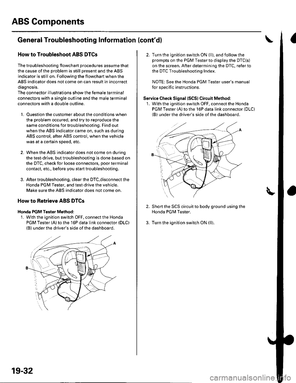
1, Wjth the ignition switch OFF, connect the Honda
PGM Tester (A) to the 16P data link connector (DLC)
(B) under the driver's side of the dashboard.
19-32
2. Turn the ignition switch ON (ll), and follow the
prompts on the PGM Tester to display the DTC{S)
on the screen. After determining the DTC, refer to
the DTC Troubleshooting Index.
NOTE: See the Honda PGM Tester user's manual
for specific instructions.
Service Check Signal (SCS) Circuit Method:
1. With the ignition switch OFF, connect the Honda
PGM Tester (A) to the 16P data link connector (DLC)
(BI under the driver's side of the dashboard.
2. Short the SCS circuit to body ground using the
Honda PGM Tester.
3. Turn the ignition switch ON (ll).
Page 634 of 1139
ABS Components
System Description (cont'd)
ABS Modulator
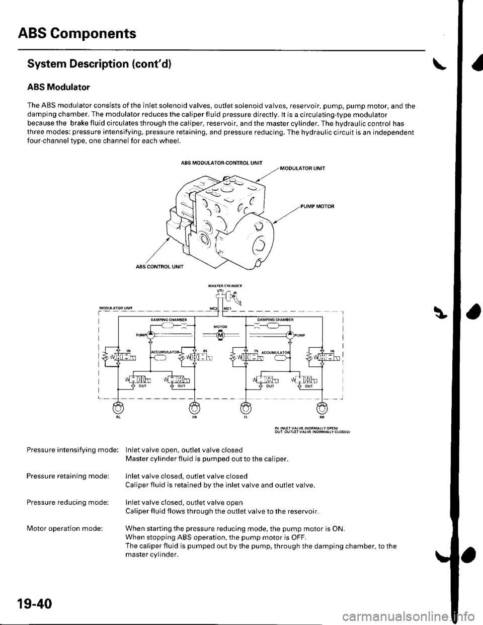
The ABS modulator consists of the inlet solenoid valves, outlet solenoid valves, reservoir, pump, pump motor, and the
damping chamber. The modulator reduces the caliper fluid pressure directly. lt is a circulating-type modulator
becausethe brakefluidcirculatesthroughthecaliper,reservoir,andthemastercylinder.Thehydrauliccontrol has
three modes: pressure intensifying, pressure retaining, and pressure reducing. The hydraulic circuit is an independent
four-channeltype, one channel for each wheel.
Pressure intensifying mode: Inletvalve open, outlel valve closed
Master cylinder fluid is pumped out to the caliper.
Pressure retaining mode: lnlet valve closed, outlet valve closed
Caliper fluid is retained by the inlet valve and outlet valve.
Pressure reducing mode: Inlet valve closed, outlet valve open
Caliper fluid flows through the outlet valve to the reservoir.
lvlotor operation mode: When starting the pressure reducing mode, the pump motor is ON.
When stopping ABS operation, the pump motor is OFF.
The caliper fluid is pumped out by the pump, through the damping chamber, to the
master cvlinder.
19-40
Page 635 of 1139
t
Wheel Sensors
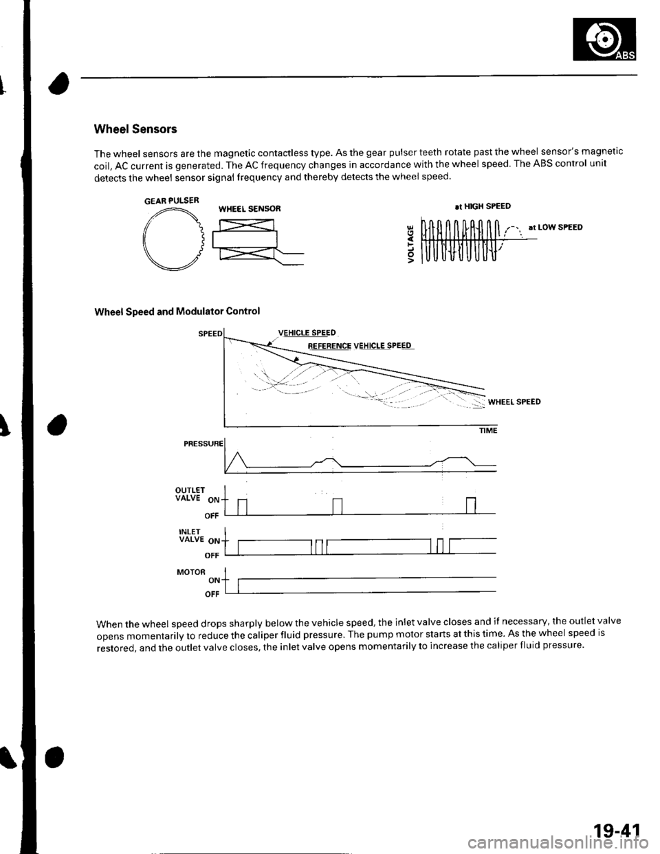
The wheel sensors are the magnetic contactless type. As the gear pulser teeth rotate past the wheel sensor's magnetic
coil, AC current is generated. The AC frequency changes in accordance with the wheel speed. The ABS control unit
detects the wheel sensor signal frequency and thereby detects the wheel speed.
!t LOW SPEED
Wheel Speed and Modulator Control
8E!EEETqE VEJ!q!ESPEEq
5
PRESSURE
OUTLETVALVE 9p
OFF
INLETVALVE oN
OFF
MoroR I-,. ltlOFF
When the wheel speed drops sharply below the vehicle speed, the inlet valve closes and il necessary, the outlet valve
opens momentarily to reduce the caliper fluid pressure. The pump motor starts at this time. As the wheel speed is
restored, and the outlet valve closes, the inlet valve opens momentarily to increase the caliper fluid pressure.
GEAR PULSERWHEEL S€NSOR.r HIGX SPEED
19-41
Page 652 of 1139
ABS Gomponents
ABS Modulator-Control Unit Removal and Installation {cont'dl
3. Disconnectthe six brake lines.
4. Remove the two I mm nuts.
5. Remove the ABS modulator-control unit (C).
Installation
'1. InstalltheABS modulatorcontrol unit, then tighten the two 8 mm nuts.
2. Align the connecting surface ofthe ABS control unit 3'lP connector.
3. PushinthelockoftheABScontrol unit 31P connector until you hear it click into place. then connect the connector.
4. Connect the six brake Iines.
5. Bleed the brake system, starting with the front wheels.
6. Connect the PGM Tester, and do the solenoid function test for each wheel.
7. Bleed the brake system again, staning with the front wheels.
8. Start the engine, and check that the ABS indicator and brake system indicator go off.
9. Disconnect the Honda PGM Tester. Test-drive the vehicle, and check that the ABS indicator and brake qvqtem
indicator do not come on.
19-58
Page 664 of 1139
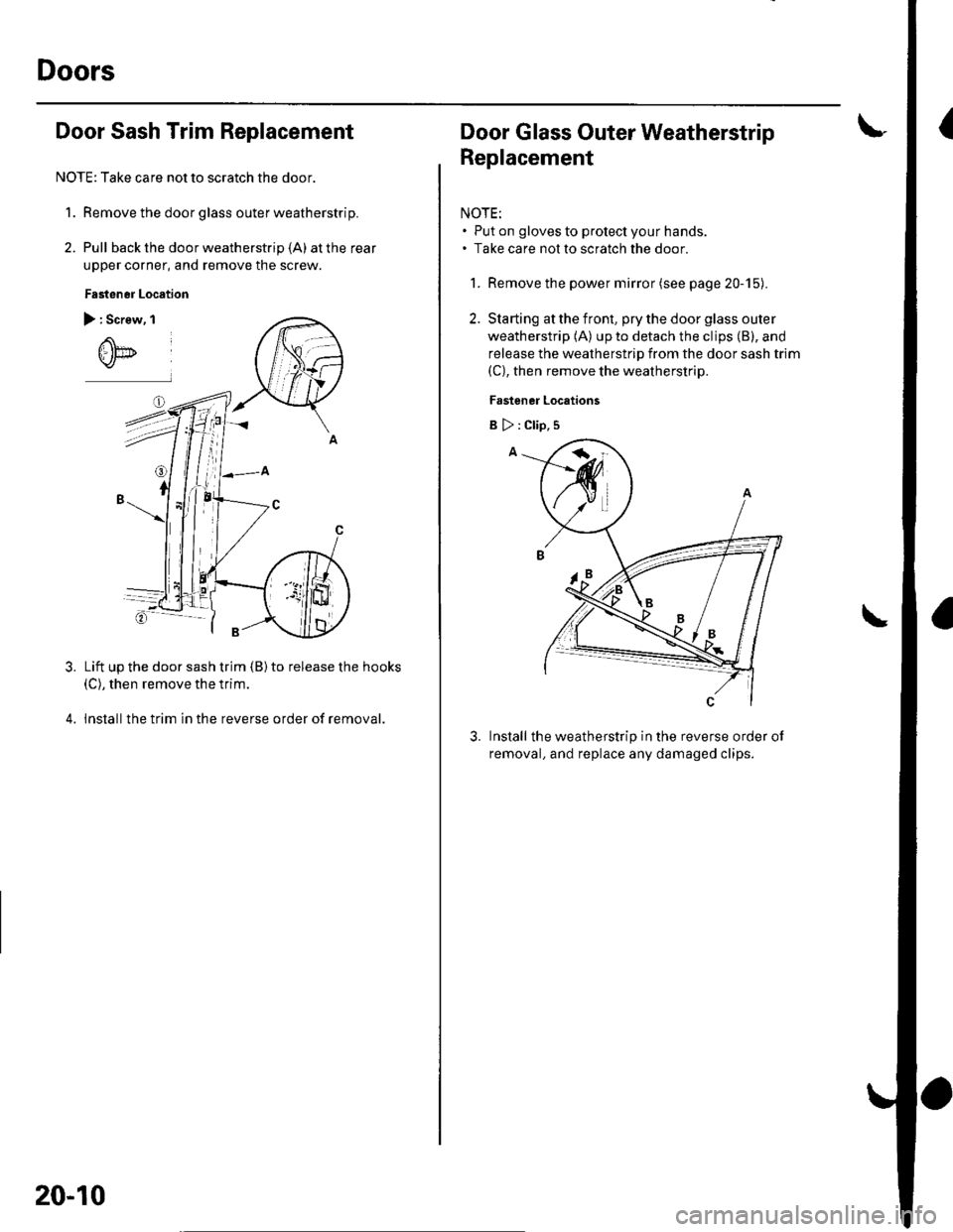
Doors
IDoor Sash Trim Replacement
NOTE: Take care not to scratch the door.
1. Remove the door glass outer weatherstrip.
2. Pull back the door weatherstrip (A) at the rear
upper corner, and remove the screw.
Fasten6r Location
) : Screw, I
Lift up the door sash trim {B) to release the hooks(C), then remove the trim.
lnstallthe trim in the reverse order of removal.
3.
20-10
Door Glass Outer Weatherstrip
Replacement
NOTE:. Put on gloves to protect your hands.. Take care not to scratch the door
1. Remove the power mirror (see page 20-15).
2. Starting at the front, pry the door glass outer
weatherstrip (A) up to detach the clips (B), and
release the weatherstrip from the door sash trim(C), then remove the weatherstrip.
Fastener Locations
Install the weatherstrip in the reverse order ot
removal, and replace any damaged clips.
3.
B>:Clip,s
Page 696 of 1139
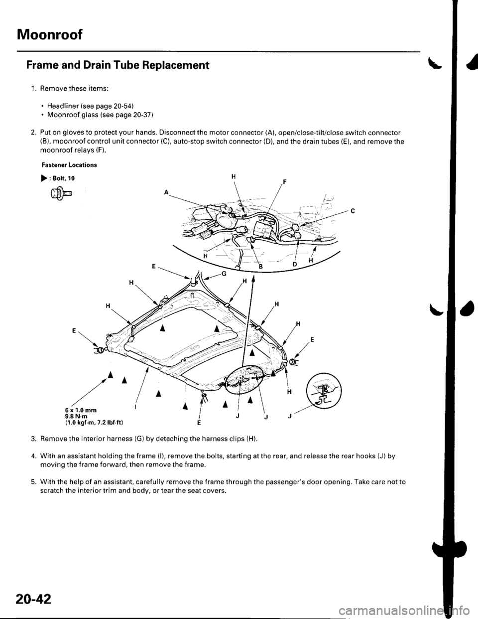
Moonroof
1.
Frame and Drain Tube Replacement
Remove these items:
. Headliner (see page 20-54). Moonroof glass (see page 20-37)
Put on gloves to protect you r hands. Disconnect the motor connector (A), open/close-tilt/close switch connector
{B), moonroof control unit connector {C), auto-stop switch connector (D), and the drain tubes (Ei, and remove the
moonroof relays (F).
Fastenor Locations
> : Bolt, 10
{um
/^
6x1.0mm9.8 N.m(1.0 kgf.m,7.2lbf ft)
4.
5.
2.
irl
@
Remove the interior harness (G) by detaching the harness clips (H).
With an assistant holding the frame (l). remove the bolts, starting at the rear, and release the rear hooks (J) by
moving the f rame forward, then remove the frame.
With the help of an assistant, carefully remove the frame through the passenger's door opening. Take care not to
scratch the interior trim and body, or tear the seat covers.
20-42
Page 711 of 1139
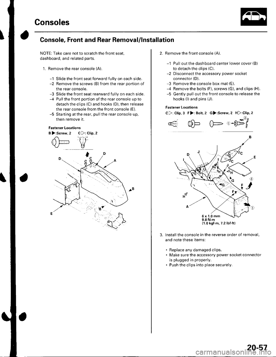
Consoles
Console, Front and Rear Removal/lnstallation
NOTE: Take care not to scratch the front seal,
dashboard, and related parts.
1. Remove the rear console (A).
-1 Slide the front seat forward fully on each side.-2 Remove the screws {B)from the rear portion of
the rear console,-3 Slide the front seat rearward fully on each side.-4 Pullthe front portion of the rear console up to
detach the clips (C) and hooks (D), then release
the rear console from the front console (E).
-5 Starting atthe rear, pullthe rear console up,
then remove it.
Fastener Locations
B >:Screw, 2 C >: Clip, 2
2. Remove the front console (A).
-1 Pull out the dashboard center lower cover {B)
to detach the clips (C).
-2 Dlsconnect the accessory power socket
connector (D).
3 Remove the console box mat (E).
-4 Remove the bolts (F), screws (G), and clips (H).
-5 Gently pull out the front console to release the
hooks (l)and pins (J).
Fastener Locations
C>:Clip,3 F>i Bolt,2 G>:Screw.2 H):Clip,2
..4- 4!-- fF- ,-('E9'/*'*q'J-L}*J\./-d
98Nm(1.0 kgt.m,7.2lbf.ft)
Install the console in the reverse order of removal,
and note these ltems:
. Replace any damaged clips.. Make sure the accessory power socket connector
is plugged in properly.
. Push the clips into place securely.
6x1.0mm
20-57
Page 844 of 1139
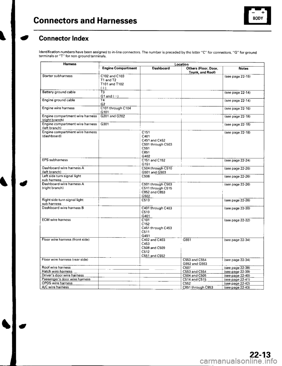
Gonnectors and Harnesses
aGonnector Index
ldentification numbers have been assigned to in-line connectors. The number is preceded by the letter "C" for connectors, "G" for groundterminals or "T" for non ground terminals.
HamessLocationEngine CompartmentDashboardOthers {Floor, Door,Trunk. and Roo{lNot€s
Starter subharnessC102 and C103T1 and T2T101 and T102
(see page 22-15)
Battery ground cableT3G'l and ( -{see page 22-l!)
Engine ground cableT4{see page 22-14)
Engine wire harnessCl0l through C104G 101(see page 22 16)
Engine compartment wire harness{rioht branchiG201 and G202(see page 22 18)
Engine compartment wire harness(left brench)G301(see page 22 18)
Engine compartment wire harness(dashboard)c401C451 and C452C501 through C503c551c851G402
(see page 22-18)
EPS subharnessC151 and C152G'151\see page 22 241
Dashboard wire harness Alleft branch)C504 through C510G501 and G503(see page 22-26)
Left side turn signal lightc506(see page 22-26)
Dashboard wire harness A(right branch)C50l through C503C5ll through C515C852 and C853G502
(see page 22-26)
Right side turn si9nal lightsub harnesslsee page 22-26)
Dashboard wire harness BC40l through C403c510G40l
(see page 22-30)
ECM wire harnessc101cl52C451 through C453c511G451
{see page 22-32}
Floorwire harness (front side)C402 and C403 G551c453C508 and C509c512C551 an.l C55?
(see page 22'34)
Floor wire harness (rear side)C553 and C554(see page 22-34)
Roo{ wire harnessc507(see paqe 22-38)Hatch wire harnessC553 and C554(s6e paqe 22'39)Driver's door wire harnessC504 and C505(see paqe 22-40)Passenqer's door wi.e harness514 and C515(see oaoe 22-41Te harness)552(see oaqe 22-42i/C wire harnessc851 rhrouoh c853(see paqe 22.43i
22-13
Page 846 of 1139
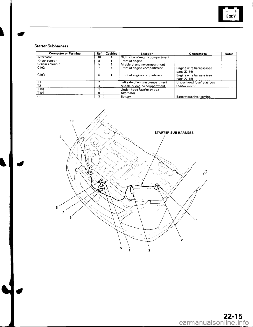
Connector or TerminalRetCavitiesLocationConnoc,ts toNotesAlternatorKnock sensorStarter solenoidc102
c103
10857
6
4116
1
Right side of eng;ne compartmentFront of engineMiddle of engine compartmentFront of engine compartment
Front of engane compartment
Engine wire harness (seepage 22 16)Engine wire harness (seeoaae 22-16)T1r224L€tt side of engine compartmentMiddle or enoine comDanmentUnder hood fuse/relay boxStaner motorT101r1021IUnder-hood fuse/relay boxAlternatorBattervBatterv positive terminal
Starter Subharness
STARTER SUB HARNESS
22-15
Page 847 of 1139
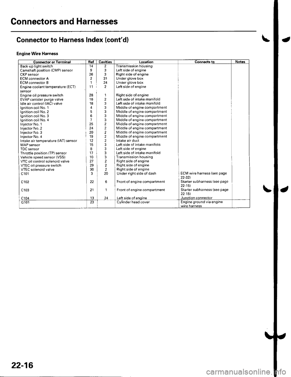
Connectors and Harnesses
Engine Wire Harness
Camshaft position (CMP) sensorLllr sensorEC[,4 connector AECI/l connector BEngine coolant temperature (ECT)
sensorEngine oil pressure switchEVAP canister purge valveldle air control (lAC)valve
lgnition coil No. llgnition coil No. 2lgnition coil No. 3lgnition coil No. 4Iniector No. 1Inlector No.2Iniector No.3Iniector No. 4Intake air temperature {lAT) sensor
TDC sensorThrottle position (TP) sensorVehicle speed sensor (VSSI
VTC oil control solenoid valveVTEC oil pressure switchVTEC solenoid valvec 101
c102
233
242
Transmission housingLeft side of engineRight side ofengineUnder glove boxUnder glove boxLeft side of engine
Bight side oI engineLeft side of intake manifoldLeft side of intake manifoldMiddle of engine compartmentMiddle of engine compartmentMiddle of engine compartmentMiddle of engine compartmentMiddle of engine compartmentMiddle of engine compartmentMiddle of engine compartmentMiddle of engine companment
28
1845672524201912
811102729303
22
12333332222233
322220
Left side of intake manifoldLeft side of engineLeft side of intake manifoldTransmission housingRight side o{ engineRight side of engineRight side of engineUnder right side of dash
Front of engine companment
Front of engine compartment
ECM wire harness {see page22-321Starter subharness (see page22-15)Starter subharness (see page22 151
Connector to Harness Index (cont'dl
22-16