Start HONDA CIVIC 2003 7.G Workshop Manual
[x] Cancel search | Manufacturer: HONDA, Model Year: 2003, Model line: CIVIC, Model: HONDA CIVIC 2003 7.GPages: 1139, PDF Size: 28.19 MB
Page 875 of 1139
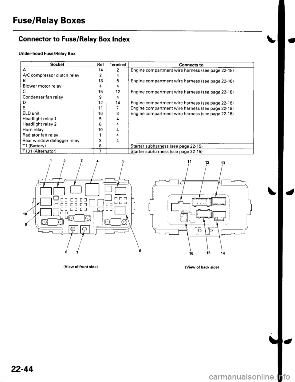
Fuse/Relay Boxes
Connector to Fuse/Relay Box Index
Under-hood Fuse/Relay Box
lview of tront sidel
- a-------) | | T---r .-:-tt || tL__.1 | I
------tttL""tt tt ttL lL ltl'".-
{View of back side)
SocketRefTerminalConnects to
Ay'C compressor clutch relay
B
Blower motor relay
c
Condenser fan relay
D
E
ELD unit
Headlight relay 1
Headlight relay 2
Horn relay
Radiator fan relay
Rear window defoqqer relay
14
2
15
91'
11
to
5
6
10'l
J
2
4
5
4
4
14
7
3
4
4
4
4
Engine compartment wire harness (see page 22-18)
Engine compartment wire harness (see page 22-18)
Engine compartment wire harness (see page 22-18)
Engine compartment wire harness (see page 22-18)
Engine compartment wire harness (see page 22-18)
Engine compartment wire harness {see page 22-18)
T1 (Batterv)8Starter subharness (see oaqe 22-15)
T101 (Alternator)7Starter subharness {see oaoe 22-'15}
""""-l- tr -l T _l T Il
I tTt Tr,/^-------lFrr^l -/1-l sz- l:!)L' lrt
22-44
Page 876 of 1139
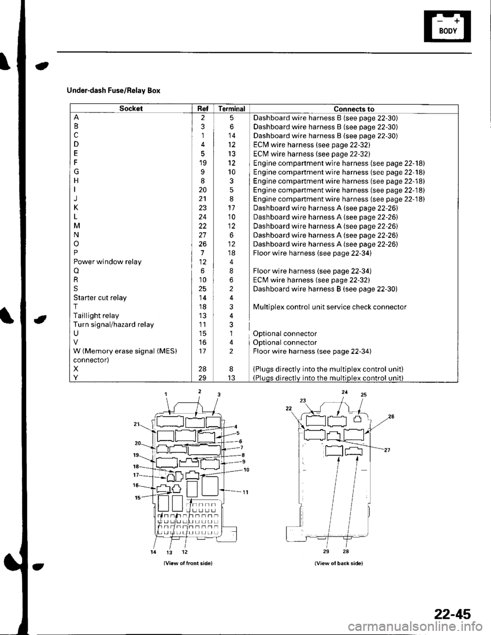
Under-dash Fuse/Relay Box
SocketRefTerminal Connects to
B
c
D
E
F
G
H
J
K
M
N
o
P
Power window relay
o
R
S
Starter cut relay
T
Taillight relay
Turn signal/hazard relay
U
W (Memory erase signal (MES)
connector)
X
Y
2
3
1
5
19
9
I
20
24
22
27
26
7
6
10
25
14
18
11
l5
to
17
28
5
6
14
13
12
10
3
:
11'10
1:
.o^
;;
4
8
2
i
nl
al
lt
2
Dashboard wire harness B {see page 22-30)
Dashboard wire harness B {see page 22-30)
Dashboard wire harness B (see page 22-30)
ECM wire harness (see page 22-32)
ECI\4 wire harness (see page 22-32)
Engine compartment wire harness (see page 22-'l8l
Engine compartment wire harness (se e page 22-181
Engine compartment wire harness (see page 22-18)
Engine compartment wire harness (se e page 22-18)
Engine compartment wire harness (see page 22-18)
Dashboard wire harness A (see page 22-26)
Dashboard wire harness A (see page 22-26)
Dashboard wire harness A (see page 22-26)
Dashboard wire harness A (see page 22-26)
Dashboard wire harness A (see page 22-26)
Floor wire harness (see page 22-34)
Floor wire harness (see page 22-34)
ECM wire harness (see page 22-32)
Dashboard wire harness B (see page 22-30)
Multiplex control unit service check connector
Optional connector
Optional connector
Floor wire harness (see page 22-34)
{Plugs directly into the multiplex control(Pluqs directlv into the multiDlex control
unat)
unrl)
I
13
tn--rlI U LI L.] L.Jh--n-UL]L]UL]
I] L] L] LI L]
!3 12
22-45
Page 882 of 1139
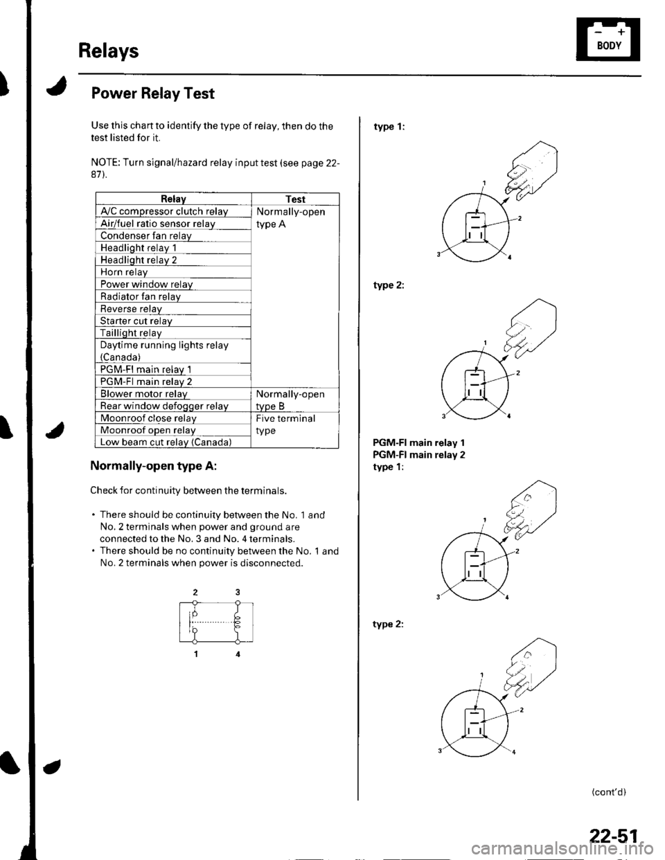
Relays
Power Relay Test
Use this chan to identify the type of relay, then do the
test listed for it.
NOTE: Turn signal/hazard relay input test (see page 22-
87).
RelayTest
A'lC comoressor clutch relavNormally-open
type AAirlfuel ratio sensor relav
Condenser fan relay
Headlioht relav 1
Headliqht relav 2
Horn relav
Power window relay
Radiator Ian relay
Reverse relav
Starter cut relav
Tailliqht relaV
Daytime running lights relay
{Canada )
PGM-FI main relav 1
PGM-Fl main relav 2
Blower motor relavNormally-open
tvpe BRear window defoqoer relav
Moonroof close relayFive terminal
typeMoonroof oDen relav
Low beam cut relav {Canada)
Normally-open type A:
Check for continuitv between the terminals.
. There should be continuity between the No. 1 and
No,2 terminals when power and ground are
connected to the No. 3 and No. 4 terminals.. There should be no continuity between the No. 1 and
No.2 terminals when power is disconnected.
type 1:
type 2:
PGM-FI main relay 1
PGM-FI main relay 2
type 1:
type 2:
(cont'd)
22-51
Page 884 of 1139
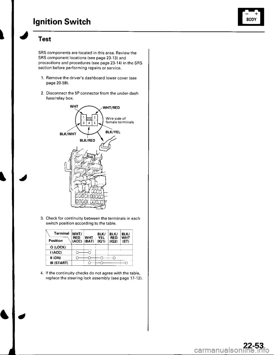
lgnition Switch
Test
SRS components are located in this area. Review the
SRS component locations (see page 23-13) andprecautions and procedures {see page 23-'l4) in the SRS
section before performing repairs or service.
1, Remove the driver's dashboard lower cover {seepage 20-59).
2. Disconnect the 5P connector from the under-dash
fuse/relay box.
WHT/RED
Wire side offemale terminals
BLK/WHTBLK/YEL
BLK/RED
Check for continuity between the terminals in each
switch position according to the table.
Terminal
p.J,i""-\
WHT/RED(ACC)
BLK/WHT YEL(BAT) flGl)
BLK/REDtrc2t
BLK/WHT(sr)
o (LocK)
| (ACC)o---o
[ (oN)
III (START)
c)-_H
o_H
lf the continuity checks do not agree with the table,
replace the steering lock assembly (see page'17-121.
22-53
Page 887 of 1139
Gauges
Self-diagnostic Procedure
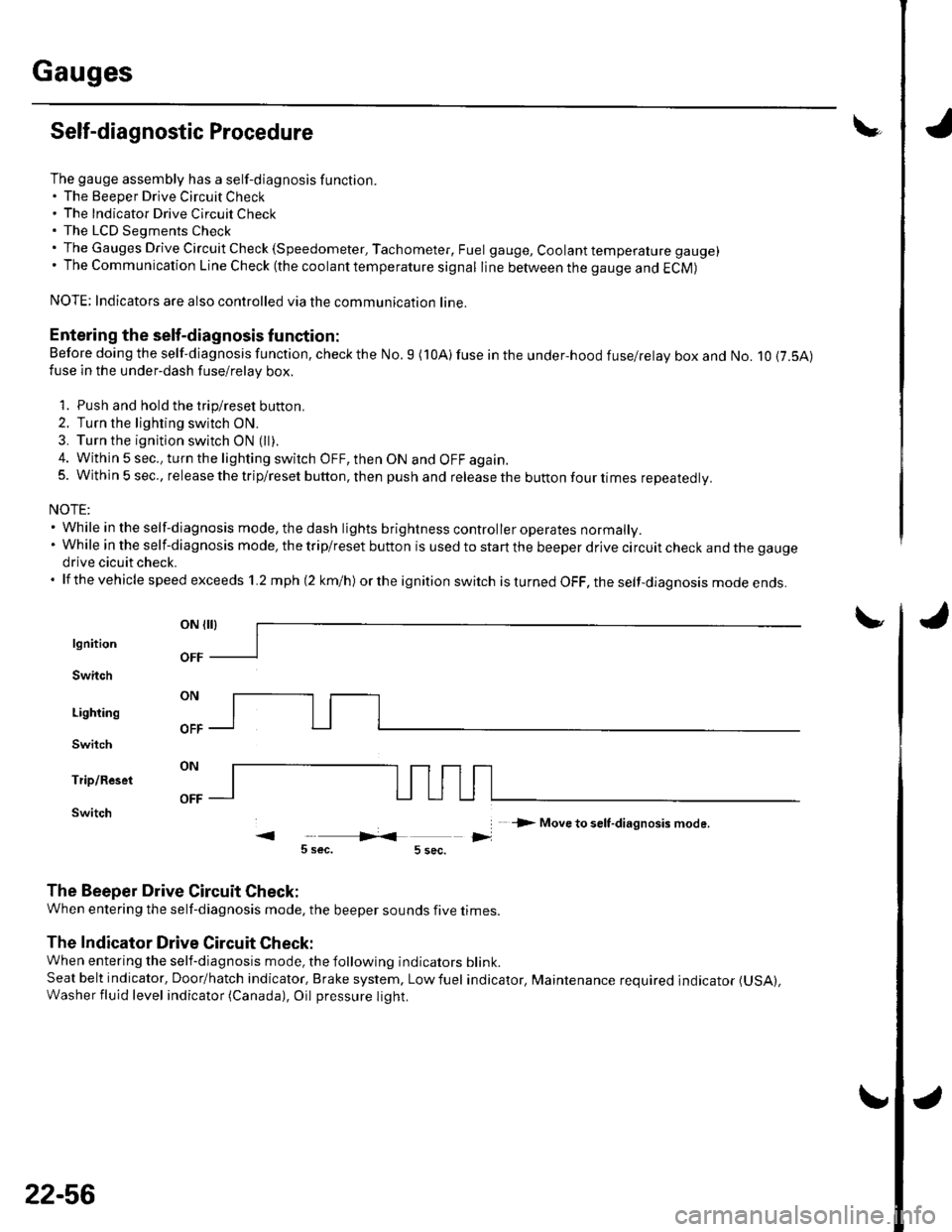
The gauge assembly has a self-diagnosis function.. The Beeper Drive Circuit Check. The Indicator Drive Circuit ChecL. The LCD Segments Check. The Gauges Drive Circuit Check (Speedometer, Tachometer, Fuel gauge, Coolant temperature gauge). The Communication Line Check (the coolanttemperature signal line between the gauge and ECM)
NOTE: Indicators are also controlled via the communication line.
Entering the self-diagnosis f unction:
Before doing the self-diagnosis function, check the No. 9 (10A) fuse in the under-hood fuse/relay box and No. 10 {7.5A)fuse in the under'dash fuse/relay box.
1. Push and hold the trip/reset button.
2. Turn the lighting switch ON.
3. Turn the ignition switch ON (ll).
4. Within 5 sec., turn the lighting switch OFF, then ON and OFF again.5. Within 5 sec., release the trip/reset button, then push and release the button four times reDeatedlv.
NOTE:. While in the self-diagnosis mode, the dash lights brightness controller operates normally.'Whileintheself-diagnosismode,thetrip/resetbuttonisusedtostartthebeeperdrivecircuitcheckandthegauge
drive cicuit check.. lf the vehicle speed exceeds 1.2 mph 12 km/h) orthe ignition switch is tu rned OFF, the self,diag nosis mode ends.
oN flrl
lgnition
Switch
Lighting
Switch
Trip/Reset
Switch-> Move to selt-diagnosis mode.
5 sec.5 sec.
The Beeper Drive Circuit Check:
When entering the self-diagnosis mode, the beeper sounds five times
The Indicator Drive Circuit Check:
When entering the self-diagnosis mode, the following indicators blink.
Seat belt indicator, Door/hatch indicator, Brake system, Lowfuel indicator, Maintenance required indicator (USA),
Washer fluid level indicator (Canada), Oil pressure light.
v
OFF
22-56
Page 888 of 1139
\
The LCD Segment Check:
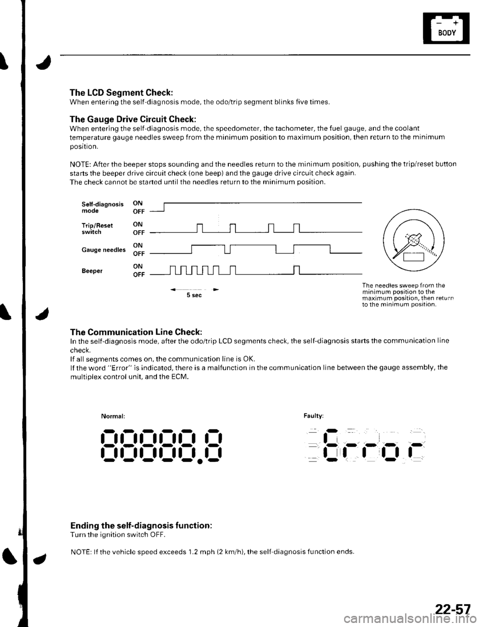
When entering the self-diagnosis mode, the odo/trip segment blinks five times.
The Gauge Drive Circuit Check:
When entering the self-diagnosis mode, the speedometer, the tachometer, the fuel gauge, and the coolant
temperature gauge needles sweep from the minimum position to maximum position, then return to the minimum
posrtron.
NOTE: After the beeper stops sounding and the needles return to the minimum position, pushing the trip/reset button
starts the beeper drive circuit check (one beep) and the gauge drive circuit check again.
The check cannot be started untilthe needles return to the minimum position.
Self-diagnosismode
Trip/Resetswitch
ON
OFF
ON r-r r-r r-r .-1 r-r r-r
;; lll u u l_l L__l I l-l
5 sec
Faulty:
The needles sweep from theminimum position to themaximum position, then returnto the minimum position-
Normal:
iD
tli-
flOi-
Ending the self-diagnosis function:
Turn the ignition switch OFF.
NOTEr lf the vehicle speed exceeds 1.2 mph {2 km/h), the self diagnosis fu nction ends.
:-l!:!!JlJ!J
,-
t,-- - ,- r- i-
| | | ttfi- r-
9l- r n =--llJL--oFF _---
cause needles Xl" f---U---------l [-----l
Beeper
The Communication Line Check:
In the self-diagnosis mode, after the odo/trip LCD segments check, the self-diagnosis starts the communication line
cnecK.
lf all segments comes on, the communication line is OK.
lf the word "Error" is indicated, there is a malfunction in the communication line between the gauge assembly. the
multiDlex control unit. and the ECM.
@,
22-57
Page 895 of 1139
Gauges
2.
3.
Gauge Assembly Replacement
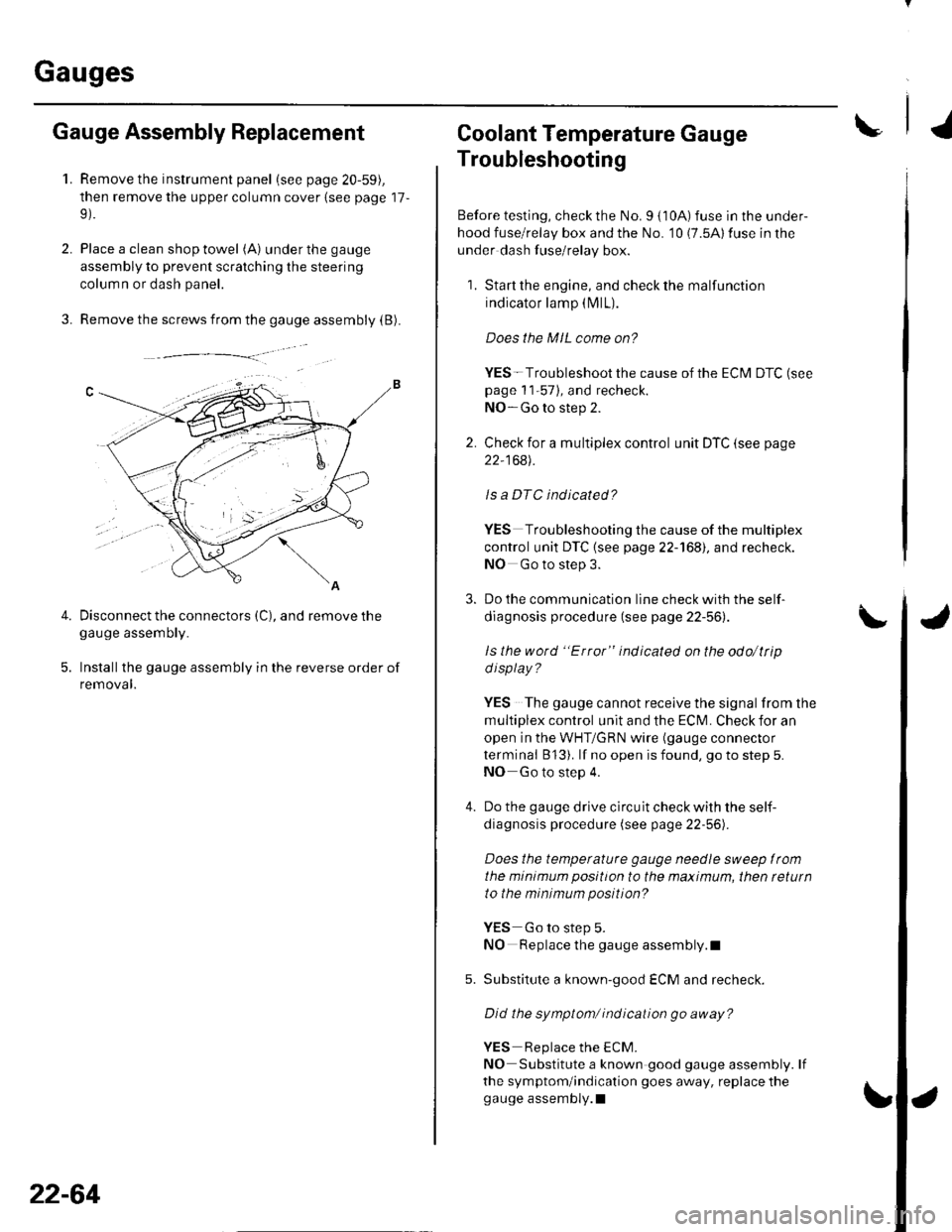
1.Remove the instrument panel (see page 20-59),
then remove the upper column cover {see page 17-
Place a clean shop towel (A) under the gauge
assembly to prevent scratching the steering
colum n or dash panel.
Remove the screws from the gauge assembly (B).
Disconnect the connectors (C), and remove thegauge assemDry.
Installthe gauge assembly in the reverse order of
removal.
Coolant Temperature Gauge
Troubleshooting
Before testing, check the No. I { 10A) fuse in the under-
hood fuse/relay box and the No. '10 (7.5A) fuse in the
under dash fuse/relay box.
1. Start the engine, and check the malfunction
indicator lamp (MlL).
Does the MIL come on?
YES- Troubleshoot the cause of the ECM DTC (see
page 1 1-57), and recheck.
NO-Go to step 2.
2. Check for a multiplex control unit DTC (see page
22,168).
ls a DTC ind icated?
YES Troubleshooting the cause of the multiplex
control unit DTC {see page 22-168), and recheck.
NO Go to step 3.
3. Do the communication line check with the self-
diagnosis procedure (see page 22-56).
ls the word "Error" indicated on the odo/ttip
d isplay ?
YES The gauge cannot receive the signal from the
multiplex control unit and the ECI\,4. Check for an
open in the WHT/GRN wire (gauge connector
terminal B 13). lf no open is found, go to step 5.
NO Go to step 4.
4. Do the gauge drive circuit check with the self-
diagnosis procedure (see page 22-56).
Does the temperature gauge needle sweep lrom
the minimum position to the maximum, then tetutn
to the minimum position?
YES Go to step 5.
NO Replace the gauge assembly.l
5. Substitute a known-good ECM and recheck.
Did the symptom/ ind ication go away?
YES Replace the ECM.
NO Substitute a known good gauge assembly. lf
the symptom/indication goes away, replace thegauge assembly.l
4.
22-64
Page 994 of 1139
System Description
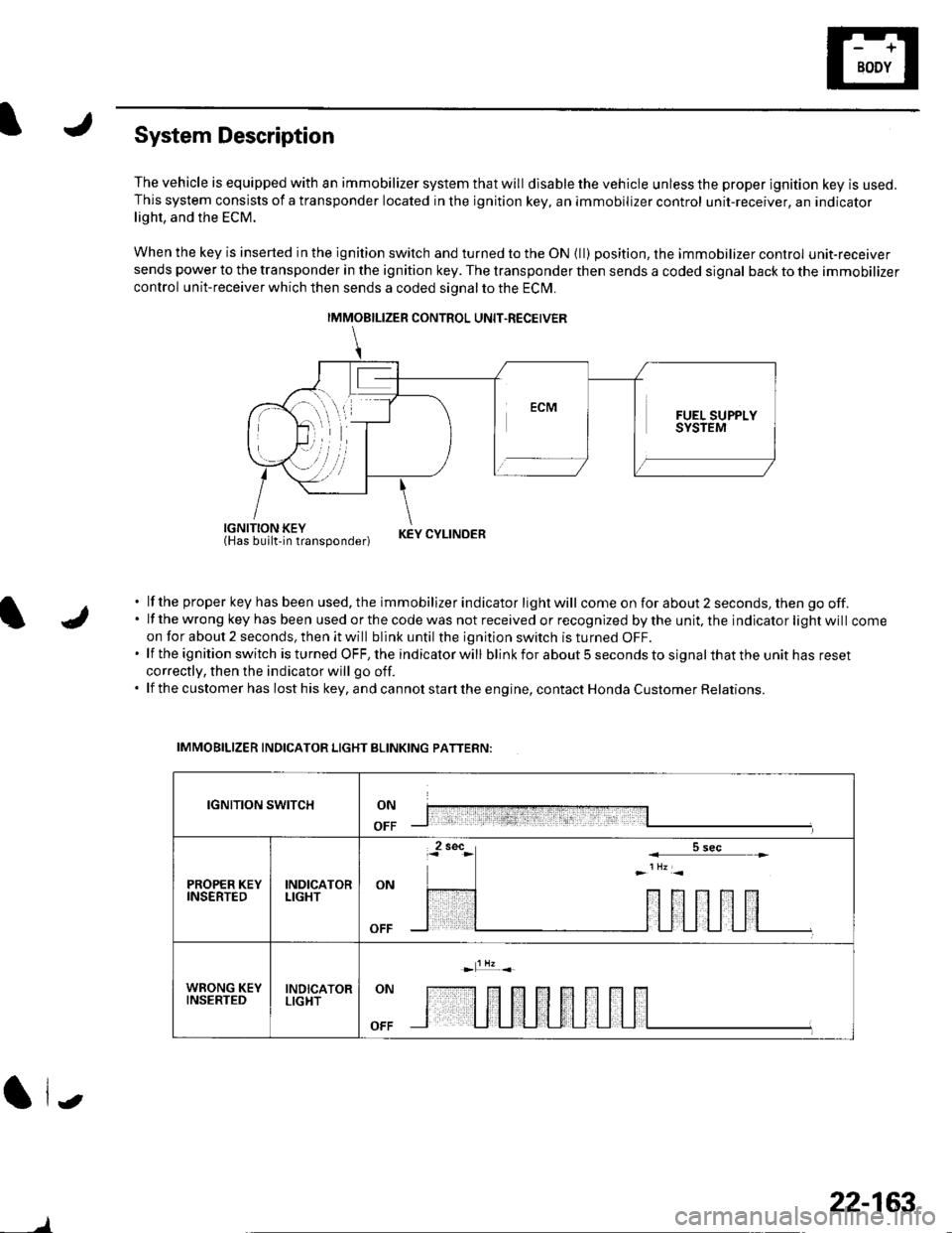
The vehicle is equipped with an immobilizer system that will disable the vehicle unless the proper ignition key is used.This system consists of a transponder located in the ignition key, an immobilizer control unit-receiver, an indicatorlight, and the ECM.
When the key is inserted in the ignition switch and turned to the ON {ll) position, the immobilizer control unit-receiversends power to the transponder in the ignition key. The transponder then sends a coded signal back to the immobilizer
control unit-receiver which then sends a coded signal to the ECI\4.
iEl'JUiliii'tlun"oona"|.r KEYCYLTNDER
lf the proper key has been used, the immobilizer indicator light will come on for about 2 seconds, then go off.lf the wrong key has been used or the code was not received or recognized by the unit, the indicator light will comeon for about 2 seconds, then it will blink until the ignition switch is turned OFF.lf the ignition switch is turned OFF, the indicator will blink for about 5 seconds to signal that the unit has reset
correctly, then the indicator will go off.
lf the customer has lost his key, and cannot start the engine, contact Honda Customer Relations.
IMMOBILIZER INDICATOR LIGHT BLINKING PATTERN:
IGNITION SWITCHON
OFF
PROPER KEYINSERTEDINDICATORLIGHTON
WRONG KEYINSERTEDINDICATORLIGHTON
OFF
(| i.,
IMMOBILIZER CONTROL UNIT.RECEIVER
)
22-163
Page 996 of 1139
)
I
Troubleshooting
Before troubleshooting the immobilizer system,
troubleshoot any EClvl Diagnostic Trouble Codes (DTCS)
(see page 11-3), and make sure the ECM has no
malfunction.
Note these items before trou bleshooting:
. Due to the action of the immobilizer system, the
engine takes slightly more time to start than on a
vehicle without an immobilizer system.. When the system is normal, and the proper key is
inserted, the indicator light comes on for 2 seconds,
then it will go off.. If the indicatorstartsto blink after 2 seconds, or if the
engine does not start. remove any other immobilizer
keys or large key fobs on the key ring, then repeat the
starting procedure.
lf the engine still does not start, continue with thisprocedure.
1. Turn the ignition switch ON {ll) with proper key.
2. Check to see if the immobilizer indicator light
comes on.
Does the indicator light blink?
YES Disconnect the 7P connector from the
immobilizer control unit-receiver, then go to step 9.
NO Check for these problems, then go to step 3.
. Blown No. 9 (10A)fuse in the under-hood
fuse/relay box.I. An open in the wire between the gauge assembly
and the immobilizer control unit-receiver.l. A faulty immobilizer indicator light,I. An open in the wire between the gauge assembly
and the under-hood fuse/relay box.l
Remove the driver's dashboard lower cover (see
page 20-59).
Remove the steering column lower cover (see page
11-9).
l
-_--t
22-165
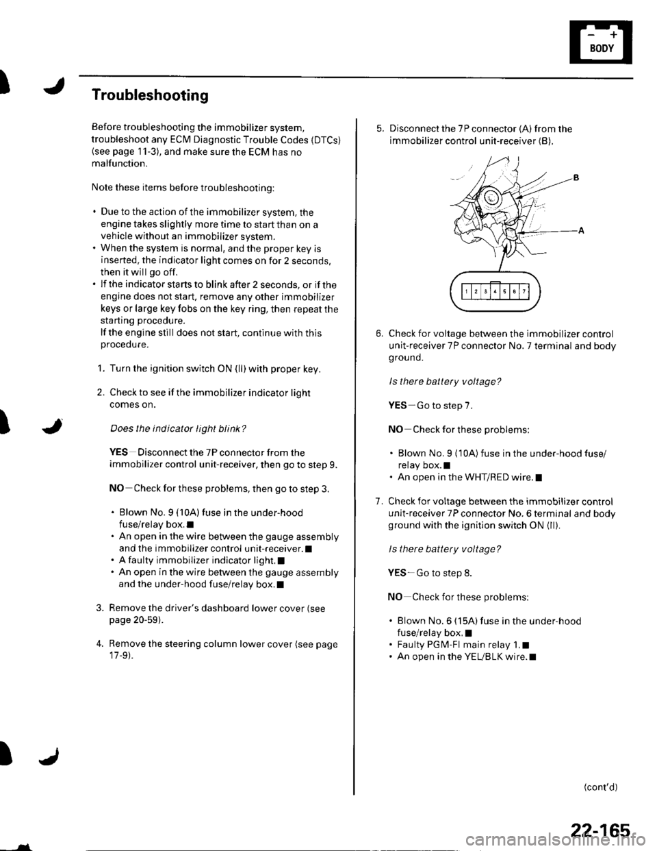
5. Disconnect the 7P connector (A)from the
immobilizer control unit-receiver (B),
Check for voltage between the immobilizer control
unit-receiver 7P connector No. 7 terminal and body
ground.
ls there battery voltage?
YES-Go to step 7.
NO Check for these problems;
. Blown No. 9 {10A)fuse in the under-hood fuse/
relay box.l. An open in the WHT/RED wire.l
Check for voltage between the immobilizer control
unit-receiver 7P connector No. 6 terminal and bodyground with the ignition switch ON {ll).
ls there battery voltage?
YES- Go to step 8.
NO Check for these problems:
. Blown No.6 (15A)fuse in the under-hood
fuse/relay box,I. Faulty PGM-Fl main relay 1,t. An open in the YEUBLK wire.l
1.
(cont'd)
Page 1033 of 1139
sRs
General Troubleshooting Information (cont'dl
Erasing the DTG Memory
Specisl Tool Required
SCS service connector 07PAz-0010100
To erase the DTC(S)from the SRS unit, use a Honda
PGM Tester {see lhe Honda PGfM Tester SRS Vehicle
System Supplement) or the following procedure.
1. Make sure the ignition switch is OFF.
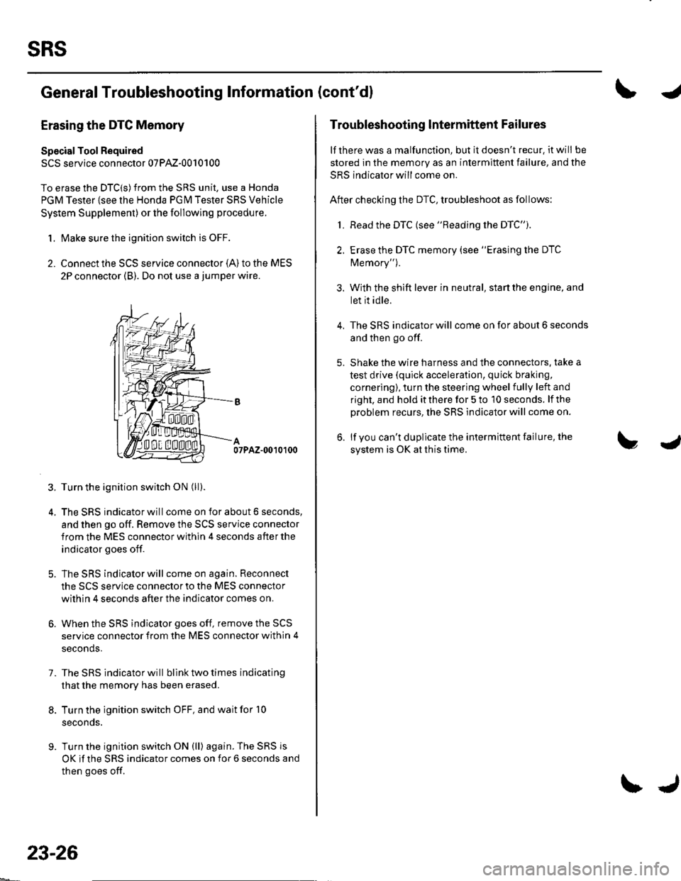
2. Connect the SCS service connector {A) to the MES
2P connector (B). Do not use a jumper wire.
07PAZ-0010100
3. Turn the ignition switch ON (ll).
4. The SRS indicator will come on for about 6 seconds,
and then go off. Remove the SCS service connector
from the MES connector within 4 seconds after the
indicator goes off.
5. The SRS indicator will come on again. Reconnect
the SCS service connector to the MES connector
within 4 seconds after the indicator comes on.
6. When the SRS indicator goes off, remove the SCS
service connector from the MES connector within 4
seconds.
7. The SRS indicator will bllnk two times indicating
that the memory has been erased.
8. Turn the ignition switch OFF, and wait for '10
seconds.
9. Turn the ignition switch ON (ll) again. The SRS js
OK if the SRS indicator comes on for 6 seconds and
then goes off.
23-26
\J
Troubleshooting lntermittent Failures
lf there was a malfunction, but it doesn't recur. it will be
stored in the memory as an intermittent failure, and the
SRS indicator will come on.
After checking the DTC, troubleshoot as follows:
1. Read the DTC (see "Reading the DTC").
2. Erase the DTC memory (see "Erasing the DTC
Memory").
3. With the shift lever in neutral, start the engine, and
let it idle.
The SRS indicator will come on for about 6 seconds
and then go off.
Shake the wire harness and the connectors. take a
test drive (quick acceleration, quick braking,
cornering), turn the steering wheel fully left and
right, and hold it there for 5 to '10 seconds. lf the
problem recurs, the SRS indicator will come on.
lf you can't duplicate the intermittent failure, the
system is OK at this time.
4.