HONDA CIVIC 2003 7.G Workshop Manual
CIVIC 2003 7.G
HONDA
HONDA
https://www.carmanualsonline.info/img/13/5744/w960_5744-0.png
HONDA CIVIC 2003 7.G Workshop Manual
Page 965 of 1139
Wipers/Washers
Component Location Index
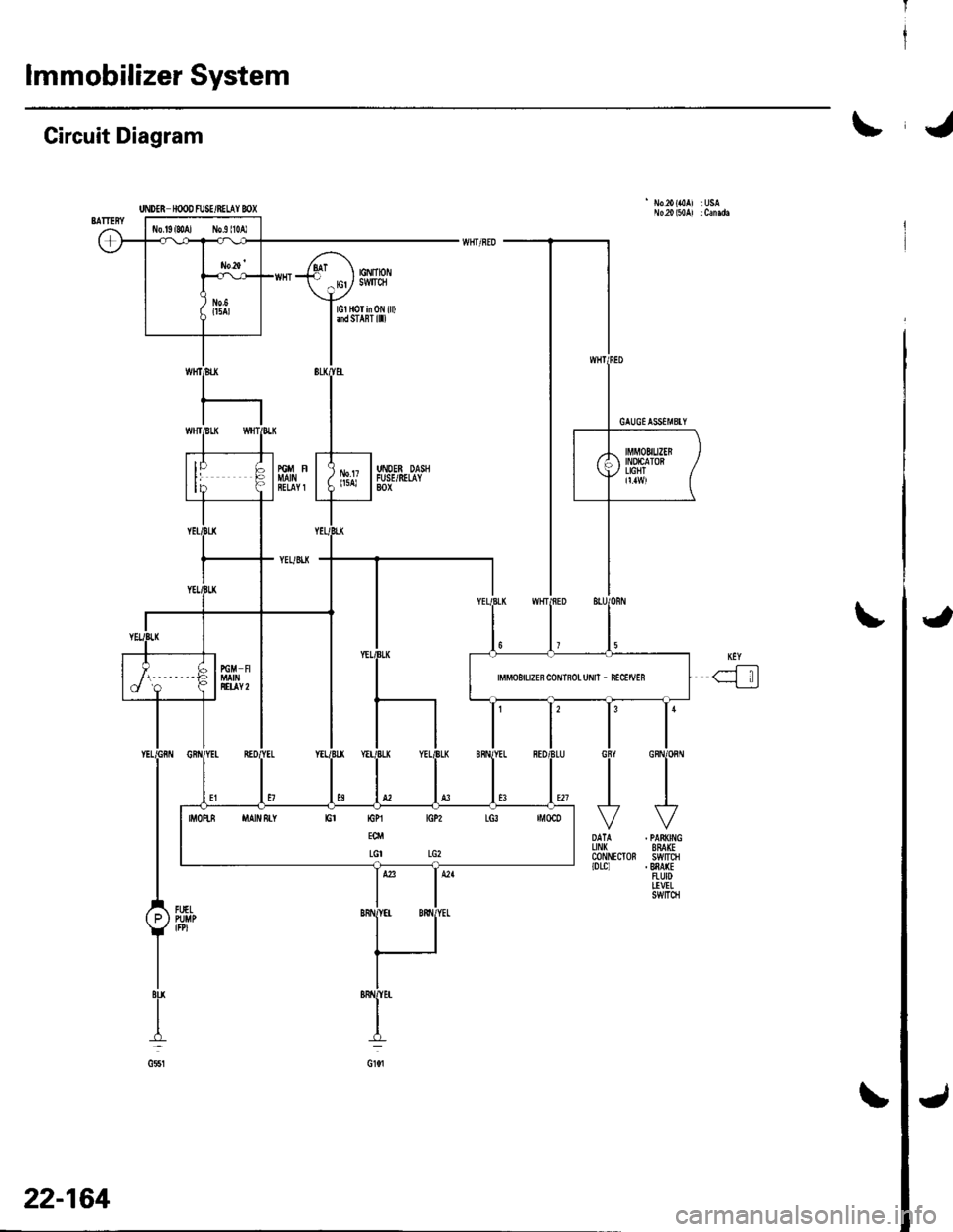
WINDSHIELD WIPER MOTORTest, page 22-'143Replacement, page 22-145
WINDSHIELD WIPER ARMS and LINKAGEReplacement, page 22-'145
WIPER/WASHER SWITCHTest, page 22-140Replacement,page 22 140
UNDER.DASHFUSE/RELAY BOX
INTERMITTENT WIPER CIRCUITlln the multiplex control unit)Input Test, page 22-138
22-134
Page 967 of 1139
Wipers/Washers
Circuit Diagram - Windshield
UNOEN HOOD FL]SE/8ELAY BOX IGNITIONSWITCN'7{ F;^--il I 6\
U-I^-- -':-;--u,Hr-
o,f-''*""
\1
L\'
MULTIPIIXcoiln0LUNIT
22-136
\,!
Page 968 of 1139
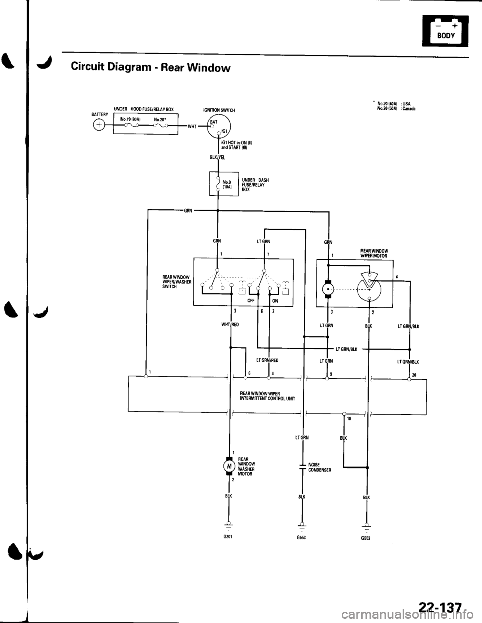
Circuit Diagram - Rear Window
UI\IOIF H@O FUSE/RELAY MX GNMOIIISW|ICH
- No2olaoAl :USA
BATTERY r----------------;i l No'g,soA, ro2o. | /,^1\(-;1_=l----_--_fww{"-' l
\+ylErHorb0Ni||l
I andsra8r 0
ffAn w$tDow wtPEEINTE$'ITTEI'IT C{)NNOL UI'/IT
f--------------- li
22-137
Page 980 of 1139
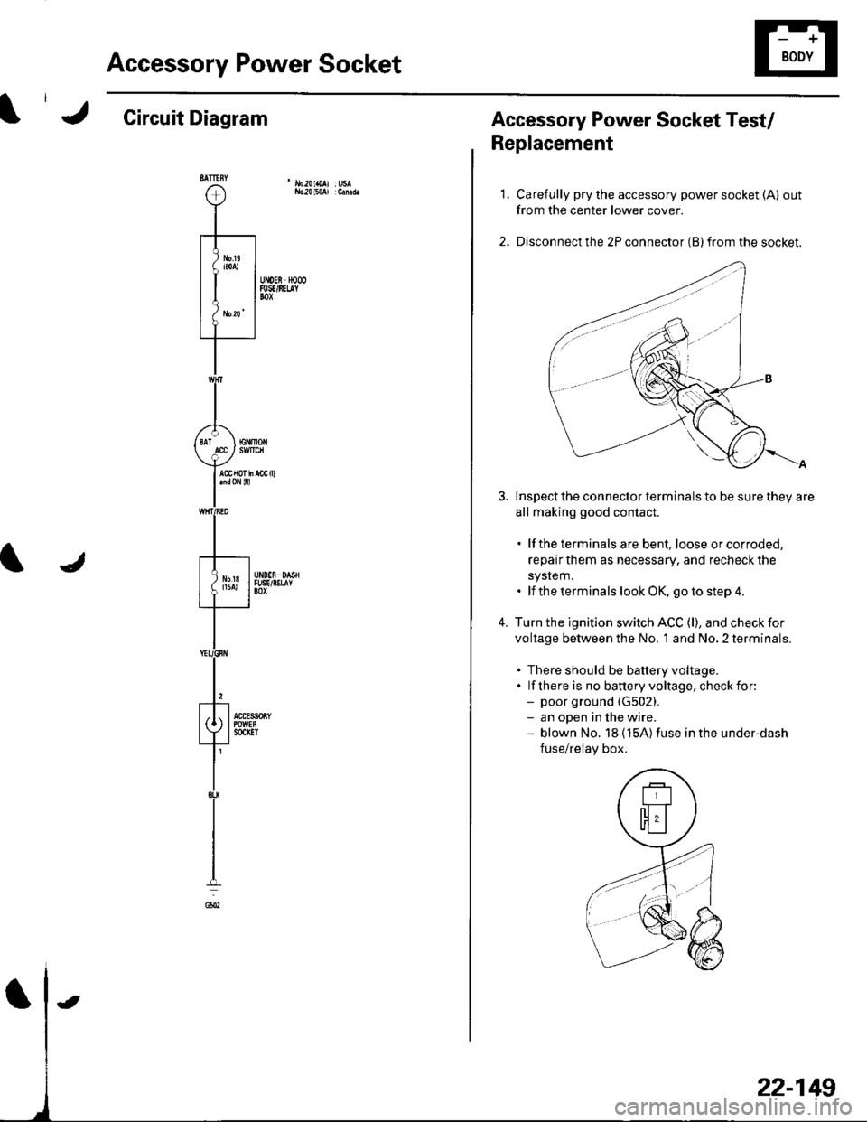
Accessory Power Socket
Circuit Diagram
22-149
Accessory Power Socket Test/
Replacement
1.
4.
Carefully pry the accessory power socket (A) out
from the center lower cover.
Disconnect the 2P connector (B) from the socket.
Inspect the connector terminals to be sure they are
all making good contact.
. lf the terminals are bent, loose orcorroded,
repairthem as necessary, and recheck the
system.. lf the terminals look OK, go to step 4.
Turn the ignition switch ACC (l), and check for
voltage between the No. 'l and No. 2 terminals.
. There should be battery voltage.. lf there is no banery voltage, checkfor:- poor ground {G502).- an open in the wire.- blown No. 18 (15A)fuse in the under-dash
fuse/relay box.
Page 982 of 1139
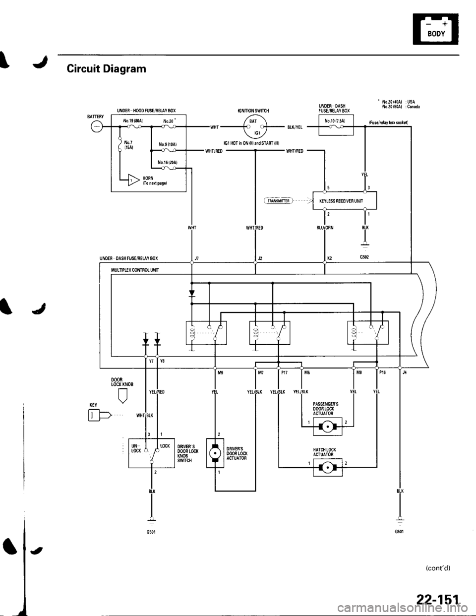
J\Circuit Diagram
UNOEE DASHfUSE/SELAYBOXUiDEN HooD FUSE/RETIY 8OX
UI'IDE8 DASH f USE/RETAY 80X
/ 8Ar \-) cl- lG1 ,/
lG1 HoT in 0N (lllaidSTAfft(llll
JI
000RLoc( KNOE
tl
xtY \"2
t'-F>Li___J-
(cont'd)
22-151
l3
IT
IBLK
I
G502
MULTIPUX CONTNo! Uflfi
PASSTNGtrS0008100(ACTUATOi
DBt!'t8'�S000R 100(ACTUATOB
t
Page 983 of 1139
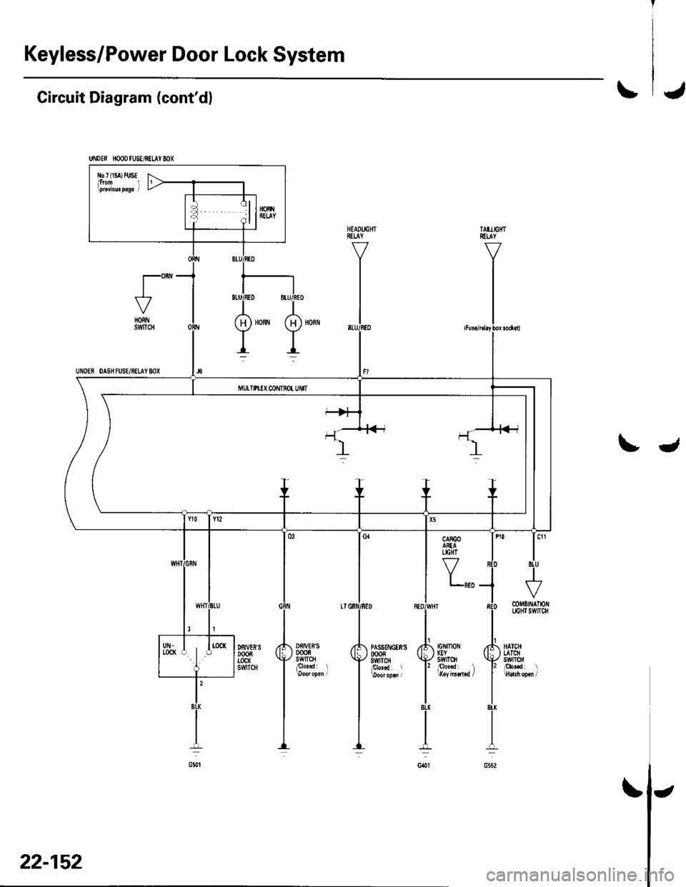
Keyless/Power Door Lock System
UNDEN HOOD FU8E/BELAY MX
l\b r t15a) FUSE
Circuit Diagram (cont'dl\J
t"-HORNSWTCH
UNDEN DAS}I FUSE/8ELAY 8OX
tJ
Y,,,
Df,IVEB'S0008swtrcHplo'.d l
DFIVES'SDOOBTOCK6WTCH
tG tltot IGYstvrTcH
mMErNAlloflLIGHI SWITCH
HATCHLATCHswlrol
22-152
\
Page 995 of 1139
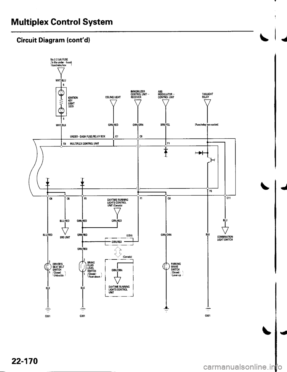
lmmobilizer System
J
I
UNDTR rcOD FUSE/RELAY 8OX
rGNtTt0i/swlrcH
lct HoT in 0N {ll).nd SIAnT l|l)
0R8 itAWStY tct tGPl tGPz LG3 |M0CD
EC
LGI LG2
t
' No20(LAl r USA
Circuit Diagram
FGN
8ELAY1
YEUBIJ(
t
DATA . PA8(II'IGLIN( SMIGCONNECIOR SWITCH{0Lcl .8nA{EFTUIDI!VELSWTfi
22-164
\J
Page 1000 of 1139
ICircuit Diagram
' I'10.20 {a0AJ :usAib.a)l50A) :C.nd.IGNITiON SWITCH
/ BAI \--_to oJ- BLI,'YEL tcl ./
J
G201
HAICIILATCHSWITCH
{cont'd)
UiIDM HOOD IUSE/NEUY BOX
MULTIPLEXc0NT80rtNsPECTror!CONNECIOF
UNDEf, DASHFUSE/NEUYBOX
22-169
Page 1001 of 1139
Multiplex Control System
J
J
Circuit Diagram (cont'd)
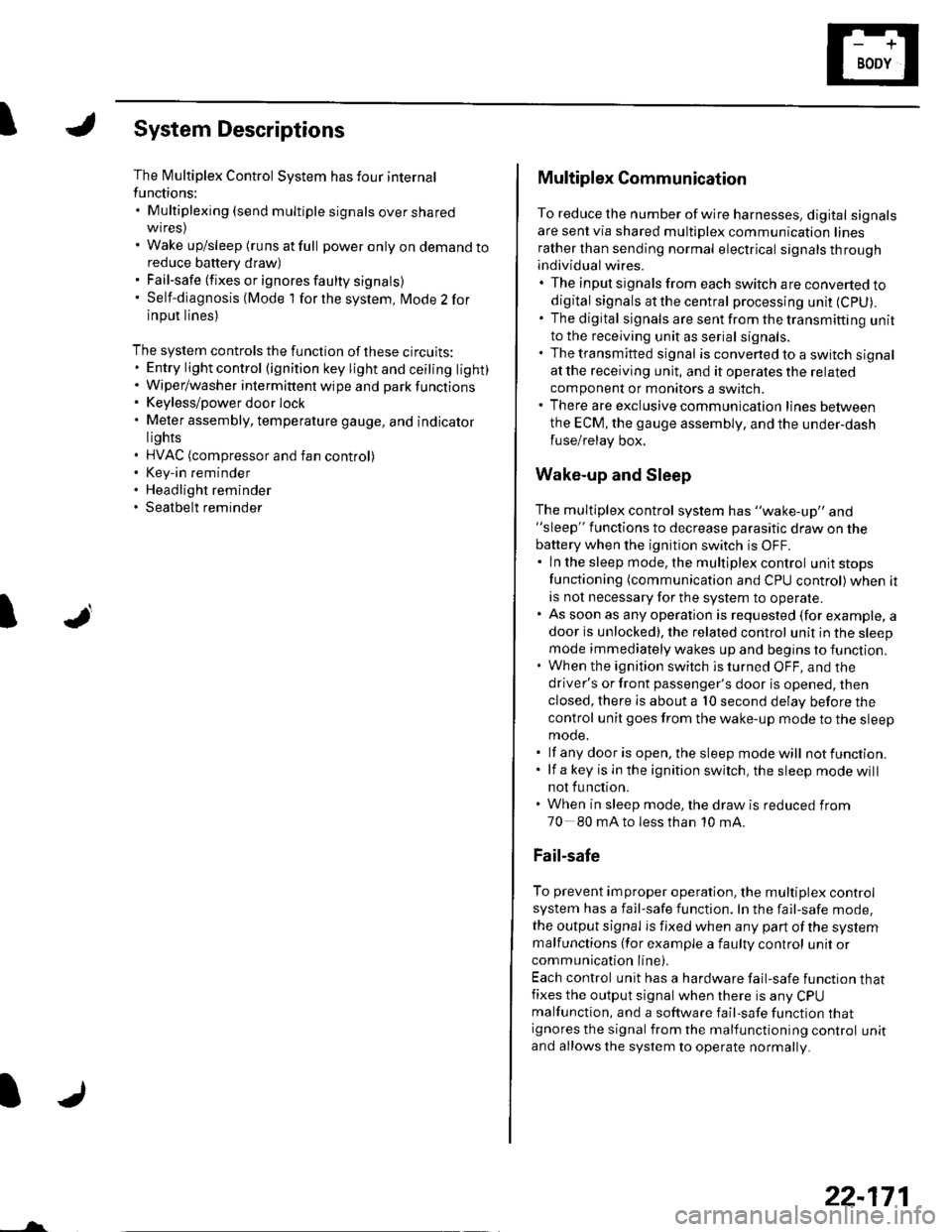
l'1o.3 l7.5AJ tUStlln$.uidt hoodritutefd4bor I
V
IwHTPLU
l0t--t---
lrfl |
lE lnv*-| > | ucHT
lA l'*'tYl
I'
CIILING LIGHT
I.l|MOBItEER@NTIOL UIIITRECEIVEE
VI
I
22-170
{
Page 1002 of 1139
ISystem Descriptions
The Multiplex Control System has four internal
functions:. Multiplexing (send multiple signals over sharedwtres). Wake up/sleep (runs at full power only on demand toreduce battery draw). Fail-safe (fixes or ignores faulty signals). Self-diagnosis (Mode 1 for the system, Mode 2 for
input lines)
The system controls the function of these circuits:. Entry lightcontrol (ignition key lightandceiting light). Wiper/washer intermittent wipe and park functions. Keyless/power door lock. Meter assembly, temperature gauge, and indicator
lights. HVAC (compressor and fan control). Key-in reminder. Headlight reminder. Seatbelt reminder
JI
/ar
22-171
Multiplex Communication
To reduce the number of wire harnesses, digital signals
are sent via shared multiplex communication linesrather than sending normal electrical signals throughindividual wires.. The input signals from each switch are converted todigital signals at the central processing unit (CpU).. The digital signalsaresentfromthetransmitting unitto the receiving unit as serial signals.. The transmitted signal is converted to a switch signalat the receiving unit, and it operates the related
component or monitors a swltch.. There are exclusive communicalion lines between
the ECM, the gauge assembly, and the under,dash
fuse/relay box.
Wake-up and Sleep
The multiplex control system has "wake-up" and"sleep" functions to decrease parasitic draw on the
battery when the ignition switch is OFF.. ln the sleep mode, the multiplex control unit stops
functioning (communication and CPU control) when it
is not necessary for the system to operate.. As soon as any operation is requested (for example, adoor is unlocked), the related control unit in the sleep
mode immediately wakes up and begins to function.. When the ignition switch is turned OFF, and the
driver's or front passenger's door is opened, then
closed, there is about a 10 second delay before the
control unit goes from the wake-up mode to the sleepmode.. lf any door is open, the sleep mode will not function.. lf a key is in the ignition switch, the sleep mode will
not function.. When in sleep mode, the draw is reduced from
70 80 mA to less than 10 mA.
Fail-safe
To prevent improper operation, the multiplex controlsystem has a fail-safe function. In the fail-safe mode,
the output signal js fixed when any part of the systemmalfunctions (for example a faulty control unit orcommunication line).
Each control unit has a hardware fail-safe function thatfixes the output signal when there is any CPUmalfunction, and a software fail-safe function thatignores the signal from the malfunctioning control unitand allows the system to operate normally.
![HONDA CIVIC 2003 7.G Workshop Manual Wipers/Washers
Circuit Diagram - Windshield
UNOEN HOOD FL]SE/8ELAY BOX IGNITIONSWITCN7{ F;^--il I 6\
U-I^-- -:-;--u,Hr-
o,f-*""
\1
L\
MULTIPIIXcoiln0LUNIT
22-136
\,! HONDA CIVIC 2003 7.G Workshop Manual Wipers/Washers
Circuit Diagram - Windshield
UNOEN HOOD FL]SE/8ELAY BOX IGNITIONSWITCN7{ F;^--il I 6\
U-I^-- -:-;--u,Hr-
o,f-*""
\1
L\
MULTIPIIXcoiln0LUNIT
22-136
\,!](/img/13/5744/w960_5744-966.png)
