Circuit HONDA CIVIC 2003 7.G Workshop Manual
[x] Cancel search | Manufacturer: HONDA, Model Year: 2003, Model line: CIVIC, Model: HONDA CIVIC 2003 7.GPages: 1139, PDF Size: 28.19 MB
Page 803 of 1139
Heating and Air Conditioning
Compressor Clutch Circuit
Troubleshooting (cont'dl
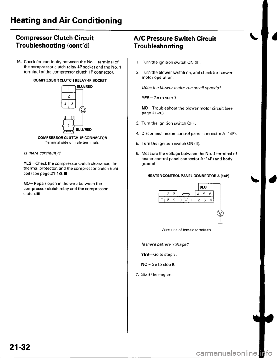
16. Check for continuity between the No. lterminal of
the compressor clutch relav 4P socket and the No. l
terminal of the compressor clutch 1P conneclor.
COMPRESSON CLUTCH RELAY 4P SOCKET
COMPRESSOR CLUTCH 1P CONNECTORTerminal side of male terminals
ls therc continuity?
YES-Check the compressor clutch clearance, the
thermal protector, and the compressor clutch field
coil (see page 21-48).I
NO-Repair open in the wire between the
compressor clutch relay and the compressor
clutch.l
21-32
A/C Pressure Switch Circuit
Troubleshooting
'1. Turn the ignition switch ON {ll).
2. Turn the blower switch on, and check for blower
motor operatron.
Does the blower motor run on all speeds?
YES Go to step 3.
NO Troubleshoot the blower motor circuit (see
page 21-20).
3. Turn the ignition switch OFF.
4. Disconnect heater control panel connectorA ('14P).
5. Turn the ignition switch ON (ll).
6. Measure the voltage between the No, 4 terminal of
heater control panel connector A {14P) and body
grou nd.
HEATER CONTROL PANEL CONNECTOR A (I4P}
1.
ls there battety voltage?
YES Go to step 7.
NO-Go to step 9.
Stan the engine.
Wire side of female termina's
Page 831 of 1139
\Body Electrical
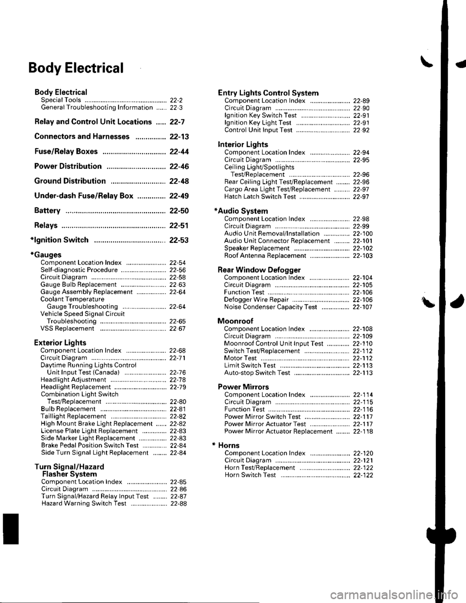
Body ElectricalSpecialToolsGeneral Troubleshooting tntorrnaiion.'......
Relay and Control Unit Locations .....
Connectors and Harnesses
Fuse/Relay Boxes ...............................
Power Distribution .............................
Ground Distribution ...........................
Under-dash Fuse/Relay Box ..............
Battery ..............
Relays ................
*lgnition Switch ..............
*Gauges
Component Location Index .......................Self-diagnostic Procedure ..........................Circuit DiagramGauge Bulb Replacement ..........................Gauge Assembly ReplacementCoolant Temperature
Gauge Troubleshooting .... ....................Vehicle Speed Signal CircuitTroubleshootingVSS Replacement
Exterior LightsComponent Location Index .......................Circuit DiagramDaytime Running Lights ControiUnit Input Test (Canada) ........................Headlight Ad,ustment .................. .. .....Headlighr Replacement ..............................Combination Light SwitchTest/ReplacementBulb ReplacementTaillight Replacement ..........................High Mount Brake Light Replacement ......License Plate Light Replacement ..............Side Marker Light Replacement ................Brake Pedal Position Switch Test ..............Side Turn Signal Light Replacement ........
Turn Signal/HazardFlasher SystemComponent Location Index .......................Circuit DiagramTurn Signal/Hazard Relay lnputTest ........Hazard Warning Switch Test
22,3
22-7
22-13
22-44
22-46
22-4A
22-49
22-50
22-51
22-53
22-5422-5622-5422 6322-64
22-64
22-6522 61
22-6822--71
22-7 622-7422-79
22-AO22-4122-8222-4222-4322-4322-4422-84
22-8�522 A622-8722-88
22-10422-105
22-10622-107
Entry Lights control systemComponent Location Index ....................... 22-89Circuit Diagram ......... 22 90lgnition Key Switch Test .....................,...... 22-9'llgnition Key Light Test ............................... 22-91Control Unit Input Test ..........,.................... 22 92
Interior LightsComponent Location Index ....................... 22-94Circuit Diagram ......... 22-95Ceiling LighVSpotlightsTesVReplacement ................................... 22-96Rear Ceiling Light TesVReplacem ent ........ 22-96Cargo Area Light Test/Replacem ent ......... 22-97Hatch Latch Switch Test ..,..,....................... 22-97
*Audio SystemComponent Location Index ....................... 22-98Circuit Diagram ......... 22,99Audio Unit Removal/lnstallation ............... 22-1OOAudio Unit Connector Replacement ......... 22-101Speaker Replacement ................................ 22-102Roof Antenna Rep1acement ....................-.. 22-103
Rear Window DefoggerComponent Location Index ...........Circuit Diasram .. ....... .. ..... ....... ...:::::.::.::.Function TestDefogger Wire Repair .................................Noise Condenser CapacityTest ................
MoonroofComponent Location Index ....................... 22-1OBCircuit Diagram ......... 22-109Moonroof Control Unit Input Test ............. 22-'l10Switch TesVReplacement ........,.....,........... 22-1 12Motor Test ................. 22-112Limit Swilch Test ...... 22-'l'13Auto-stop Switch Test ................................ 22-1 13
Power MirrorsComponent Location Index ....................... 22-114Circuit Diagram ......... 22-115Function Test ............. 22-116Power Mirror Switch Test .......................... 22-ll7Power Mirror Actuator Test ....................... 22-117Power Mirror Actuator Replacement ........ 22-11A
* HornsComponent Location Index ....................... 22-120Circuit Diagram ......... 22-121Horn TesVReplacement ...........................-. 22-122Horn Switch Test .,.... 22-122
\
Page 832 of 1139
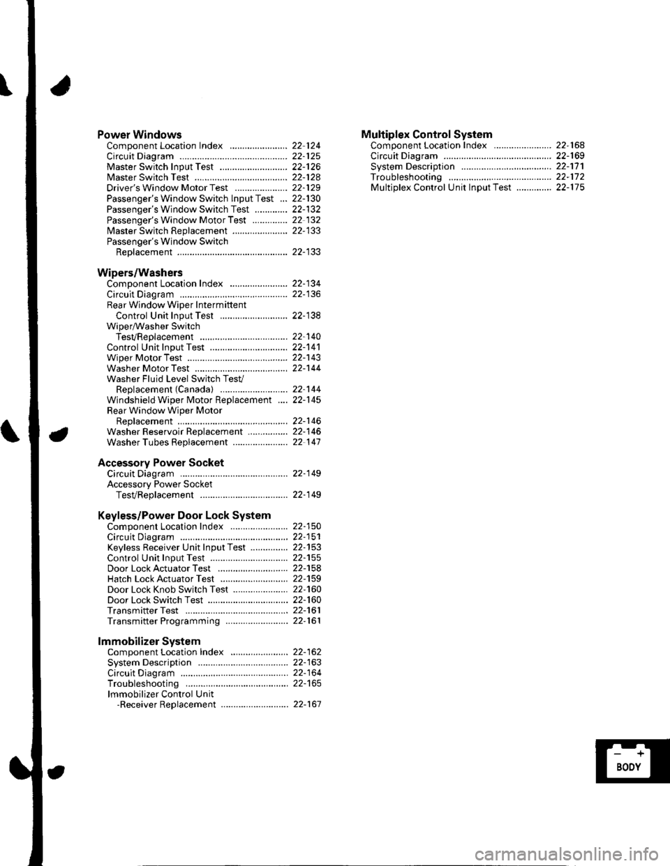
Power WindowsComponent Location Index ..........
circuit Diagram . .. ............... .........:.::::.::::.:Master Switch Input Test ...........................Master Switch TestDriver's Window Motor Test .....................
Passenger's Window Switch lnput Test ...Passenger's Window Switch Test .............
Passenger's Window Motor Test ..............
lMaster Switch Replacement ......................
Passenger's Window SwitchReplacement
Wipers/WashersComponent Location Index .......................
Circuit DiagramRear Window Wiper Intermiftent
Control Unit Input Test ...........................Wiper/Washer SwitchTesVReplacementControl Unit Input Test ...............................Wiper Motor Test
Washer Motor TestWasher Fluid Level Switch TesV
Replacement (Canadal ..........................
Windshield Wiper Motor Replacement ....
Rear Window Wiper MotorReplacementWasher Reservoir Replacement ................
Washer Tubes Beplacement ......................
Accessory Power SocketCircuit Diagram ......... 22-149
Accessory Power Socket
TesVReplacement ................................... 22-1 49
Keyless/Power Door Lock System
Component Location Index ....................... 22-150
Circuit Diagram ......... 22-151Keyless Receiver Unit InputTest ............... 22-153
Control Unit Input Test ............................... 22-155
Door LockActuatorTest .........,.......,..,.,..... 22-158Hatch LockActuatorTest ........................... 22-159
Door Lock Knob Switch Test ...................... 22-160
Door Lock Switch Test ................................ 22-160
Transmitter Test ....... 22-161
Transmitter Programming ......................... 22-161
Multiplex Control SystemComponent Location Index ...........
circuit Diagram ...... ........................::.:..:.::.:
Svstem DescriDtionTroubleshootingMultiolex Control Unit InDut Test .............
22 12422-12522-12622-12822-129
22- t30
22-13222 13222-133
22-133
22-134
22-138
22-14022-14122-14322-144
22-14422-145
22-14622-14622 147
22,16422-16922-17'l22,11222-175
lmmobilizer Systemcomponent Location Index ...........
System Description ....... ............. ..:..:..:.:...
Circuit DiagramTroubleshootinglmmobilizer Control Unit-Receiver Replacement ...........................
22-16222-16322-164
22-167
Page 837 of 1139
Body Electrical
General Troubleshooting Information (cont'dl
Five-step Troubleshooting
'1. Verify The Complaint
Turn on allthe components in the problem circuit
to verify the customer complaint. Note the
symptoms. Do not begin disassembly or testing
until you have narrowed down the problem area.
2. Analyze The Schematic
Look up the schematic for the problem circuit.
Determine how the circuit is supposed to work by
tracing the current paths from the power feed
through the circuit components to ground. lf
several circuits fail at the same time, the fuse or
ground is a Iikely cause.
Based on the symptoms and your understanding of
the circuit operation, identify one or more possible
causes of the problem.
3. lsolate The Problem By Testing The Circuit
Make circuit tests to check the diagnosis you made
in step 2. Keep in mind that a logical, simple
procedure is the key to efficient troubleshooting.
Test for the most likely cause of failure first, Try to
make tests at points that are easily accessible.
4. Fix The Problem
Once the specific problem is identified. make the
repair. Be sure to use proper tools and safe
proceoures.
5. Make Sure The Circuit Works
Turn on all components in the repaired circuit in all
modes to make sure you've fixed the entire
problem. lf the problem was a blown fuse, be sure
to test all of the circuits on the fuse. Make sure no
new problems turn up and the original problem
does not recur.
22-6
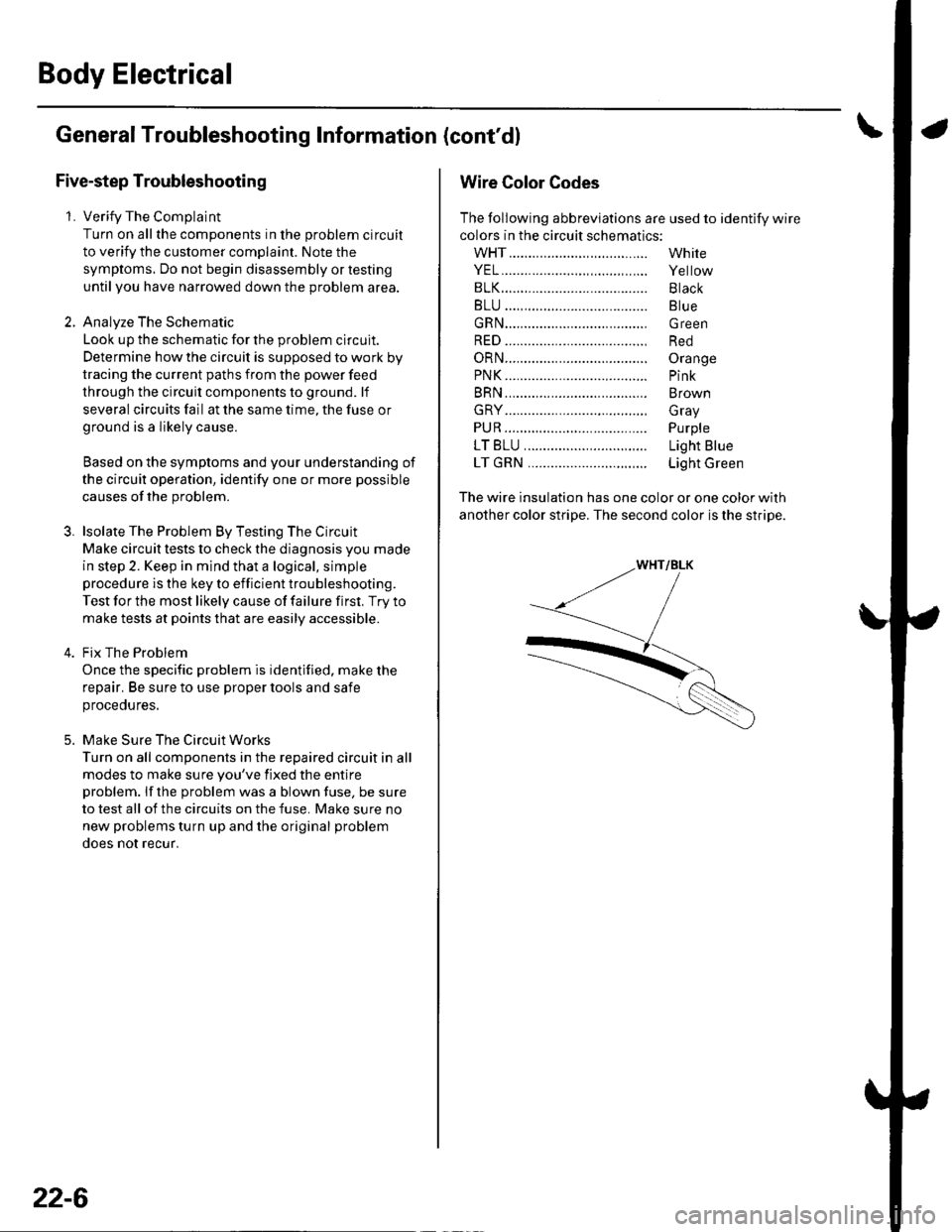
Wire Color Codes
The following abbreviations are used to identify wire
colors in the circuit schematics:
wHT....................,.,.............
YEL......................,,.......,......
B1K......................................
BLU ....,................................
GRN.....................................
RED ....................................,
oRN.....................................
PNK..........................,..........
BRN.....................................
GRY....................................,
PUR.....................................
1T81U..........................,.....
1TGRN...........................,...
White
Yellow
Black
Blue
Green
Red
Orange
Pink
Brown
Gray
Purple
Light Blue
Light Green
The wire insulation has one color or one color with
another color stripe. The second color is the stripe.
Page 877 of 1139
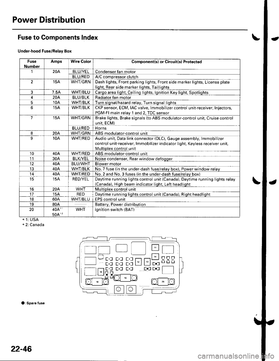
Power Distribution
Fuse to Components lndex
Under-hood Fuse/Relay Box
Fuse
Number
AmpsWire ColorComponent(sl or Circuit(s) Protected
'I204BLUI/ELCondenser fan motor
BLU/REDAy'C compressor clutch
15AWHT/GRNDash lights, Front parking lights, Front side marker lights, License plate
liqht, Rear side marker liqhts, Tailliqhts
7.5AWHT/BLUCarqo area liqht, Ceilinq liqhts. lqnition Kev liqht. Sootliohts
204BLU/BLKRadiator fan motor
510AWHT/BLKTurn siqnal/hazard relav, Turn siqnal liqhts
15AWHT/BLKCKP sensor, ECM, IAC valve, lmmobilizer control unit-receiver, Injectors,
PGM-FI main relav 1 and 2. TDC sensor
715AWHT/GRNBrake lights, Brake signals (to ABS modulator-control unit, Cruise control
unit, ECM)
BLU/REDi1 Orns
820AWHT/GRNABS modulatorcontrol unit
910AWHT/REDAudio unit, Data link connector (DLC), Gauge assembly, lmmobilizer
control unit-receiver, lmmobilizer indicator light. Keyless receiver unil,
lvlultiDlex control unit
1040AWHT/REDABS modulator-control unit
1130AB LK/YE LNoise condenser, Rear window defoqqer
40ABLU^^/HTBlower motor
IJ40AWHT/BLKNo. 7 fuse (in the under-dash fuse/relav box), Power window relav
1440AWHT/REDNo.2 and No.3 fuses (in the under-dash fuse/relav box)
t515AREDI/ELDaytime running lights control unit (Canada), Daytime running lights relay
{Canada), Hioh beam indicator liqht. Left headliqht
16204WHTMultiplex control unit
1715AREDDavtime runninq liqhts control unit (Canada). Rioht headlioht
1860AWHTiBLUEPS control unit
1980ABatterv. Power distribution
2040A'
50A'?
WHTlgnition switch (BAT)
* 1: USA" 2. Canada
O: Spare fuse
t t"| lll Itt 4t I
l l---- E'l E,l E,l r--r r---r t__J i; i6'!/'
E,l E,l E,l Eol E l f__--lI l'lr]n | |I r L__J,a ,..r^{-------l^-,
n[:]$"Lrt " N2, nf - r^l
22-46
Page 878 of 1139
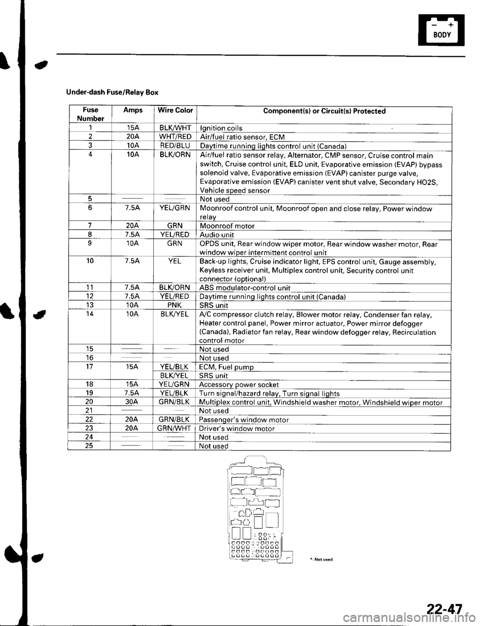
Under-dash Fuse/Relay Box
Fuse
Number
AmpsWire ColorComponent(s) or Circuit(s) Protected
115ABLKA/VHTlgnition coils
2204WHT/REDAirlfuel ratio sensor, ECM
310ARED/BLUDaytime running Iights control unit {Canada)10ABLI(ORNAir/fuel ratio sensor relay, Alternator, CMP sensor, Cruise control main
switch, Cruise control unit. ELD unit, Evaporative emission (EVAP) bypass
solenoid valve, Evaporative emission (EVAP)canister purge valve,
Evaporative emission (EVAP) canister vent shut valve, Secondary H02S,
Vehicle speed sensor
5Not used
67.5AYEUGRNMoonroof control unit, Moonroof open and close relay, Power window
relaV
7204GRNMoonroof motor
I7.5AYEUREDAudio unit
910AGRNOPDS unit, Rear window wiper motor, Rear window washer motor, Rear
window wiper intermittent control unit
107.54YELBack-up lights, Cruise indicator light, EPS control unit, Gauge assembly,
Keyless receiver unit, Multiplex control unit, Security control unit
connector (optional)
117.5ABLIVORNABS modulator-control unit
127.5AYEUREDDaytime runnino liohts control unit (Canada)
1310APNKSRS unit't410ABLK/YE LA,,/C compressor clutch relay, Blower motor relay, Condenser fan relay,
Heater control panel, Power mirror actuator, Power mirror defogger(Canada), Radiator fan relay, Rear window defogger relay, Recirculation
control motor1ENot used
loNot used
1715AYE L/B LKECM, Fuel pump
B LK/YE L>H> Unrr
1815AYEUGRNAccessory power socket
197.5AYEUBLKTurn siqnal/hazard relav, Turn siqnal liohts
2030AGRN/BLKMultiplex control unit, Windshield washer motor. Windshield wioer motor21Not used
22204GRN/BLKPassenqer's window motor
2320A.G R N,A/VHTDriver's window motor
24Not used
25Not used
__^:Hr tl_l
f at-t
at I
r^,rl fl
!!;r -
!339,i;s!!sf Fnf : |rnITf
22-47
Page 879 of 1139
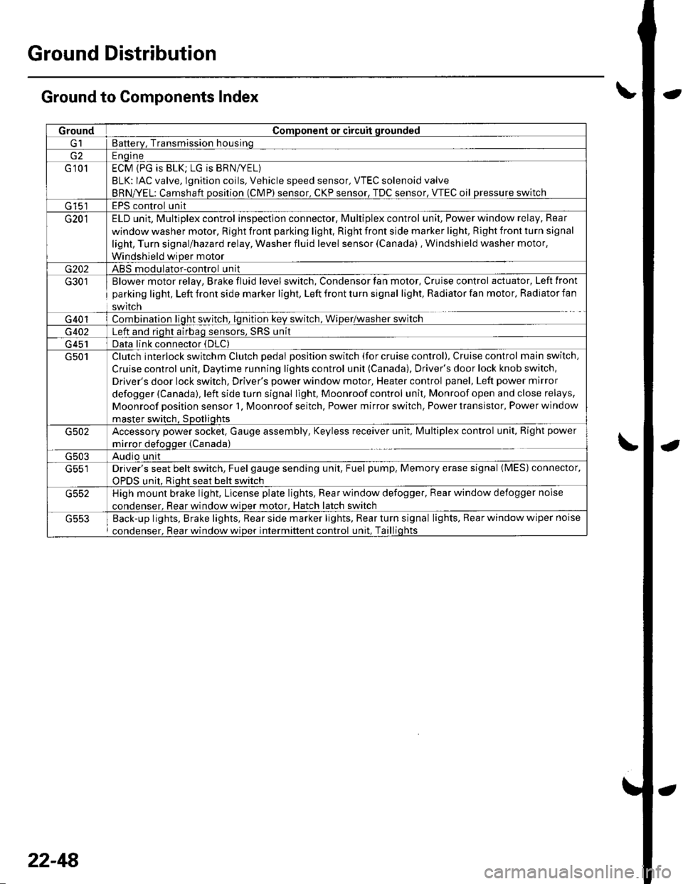
Ground Distribution
Ground to Components Index
GroundComponent or circuit qrounded
Batterv, Transmission housinq
E ngine
G 101ECM (PG is BLK; LG is BRN/YEL)
BLK: IAC valve, lgnition coils, Vehicle speed sensor, VTEC solenoid valve
BRNA/EL: Camshaft oosition (CMP) sensor. CKP sensor, TDC sensor. VTEC oil pressure switch
G 15'�]EPS control unit
G201ELD unit. Multiplex control inspection connector, Multiplex control unit, Power window relay, Rear
window washer motor, Right front parking light, Right front side marker light, Right front turn signal
light, Turn signal/hazard relay, Washer fluid level sensor (Canada) , Windshield washer motor,
Windshield wiDer motor
G202ABS modulator-control unit
G301
G401
Blower motor relay, Brake fluid level switch, Condensor fan motor, Cruise control actuator, Left front
parking light, Left front side marker light, Left front turn signal light, Radiator fan motor, Radiator fan
swrtcn
Combination liqht switch, lqnitlon kev srvitch, Wiper/wasfrer sr,virch
G402Left and riqht airbaq sensors, SRS unit
G 451Data link connector (DLC)
G501Clutch interlock switchm Clutch pedal position switch (for cruise control), Cruise control main switch,
Cruise control unit, Daytime running lights control unit (Canada), Driver's door lock knob switch,
Driver's door lock switch, Driver's power window motor, Heater control panel, Left power mirror
defogger (Canada), left side turn signal light, Moonroof control unit, Monroof open and close relays,
Moonroof position sensor '1, Moonroof seitch, Power mirror switch, Power transistor, Power window
master switch. SDotliqhts
G502Accessory power socket, Gauge assembly, Keyless receiver unit, lvlultiplex control unit, Right power
mirror defogger {Canada)
G503Audio unit
G551Driver's seat belt switch, Fuel gauge sending unit, Fuel pump, Memory erase signal (IMES) connector,
OPDS unit. Rioht seat belt switch
G552High mount brake light, License plate lights, Rear window defogger, Rear window defogger noise
condenser. Rear window wioer motor, Hatch latch switch
Back-up lights, Brake lights, Rear side marker lights, Rear turn signal lights, Rear window wiper noise
condenser, Rear window wiper intermittent control unit, Taillights
22-48
Page 881 of 1139
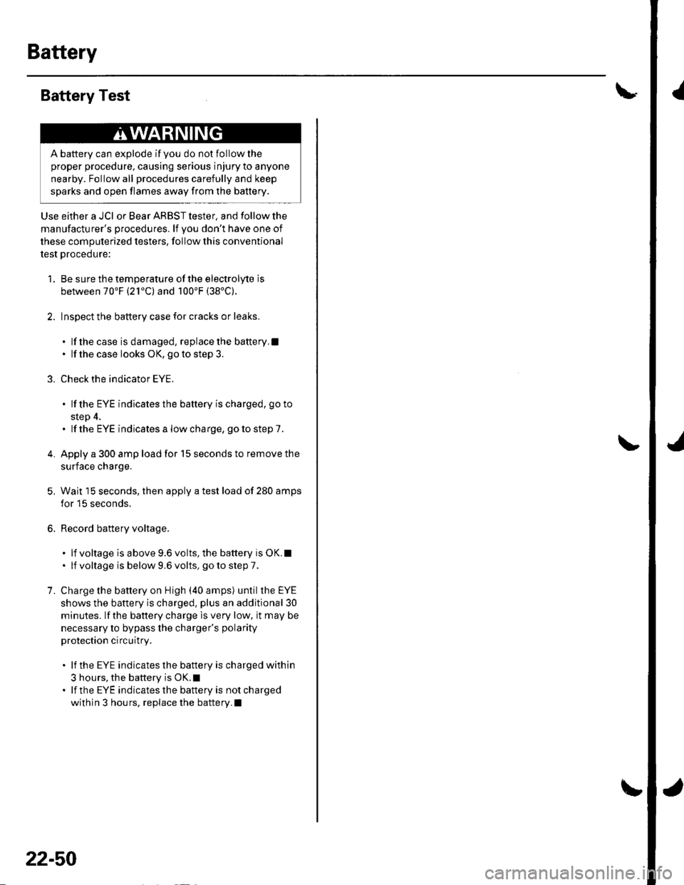
Battery
{Battery Test
Use either a JCI or Bear ARBST tester, and follow the
manufacturer's procedures. lf Vou don't have one of
these computerized testers, follow this conventional
test procedure:
1. Be sure the temperature of the electrolyte is
between 70'F (21"C) and 100'F (38'C).
2. Inspect the battery case for cracks or leaks.
. lf thecase isdamaged, replacethe battery.l. lf the case looks OK, go to step 3.
3. Check the indicator EYE.
. lf the EYE indicatesthe baftery ischarged, goto
step 4.. lf the EYE indicatesa lowcharge, gotostep7.
4. Apply a 300 amp load for 15 seconds to remove the
surface charge.
5, Wait 15 seconds, then apply a test load of 280 amps
for 15 seconds.
6. Record battery voltage.
. lf voltage is above9.6volts,the battery isOK.l. lf voltage is below9.6volts, gotostepT.
7. Charge the battery on High (40 amps) until theEYE
shows the battery is charged, plus an additional 30
minutes. lf the battery charge is very low, it may be
necessary to bypass the charger's polarity
protection circuitry.
. lf the EYE indicatesthe battery is chargedwithin
3 hours, the battery is OK.l. lf the EYE indicatesthe battery is notcharged
within 3 hours, replace the battery.l
A battery can explode if you do not follow the
proper procedure, causing serious injury to anyone
nearby. Follow all procedures carefully and keep
sparks and open flames away from the battery.
22-50
Page 886 of 1139
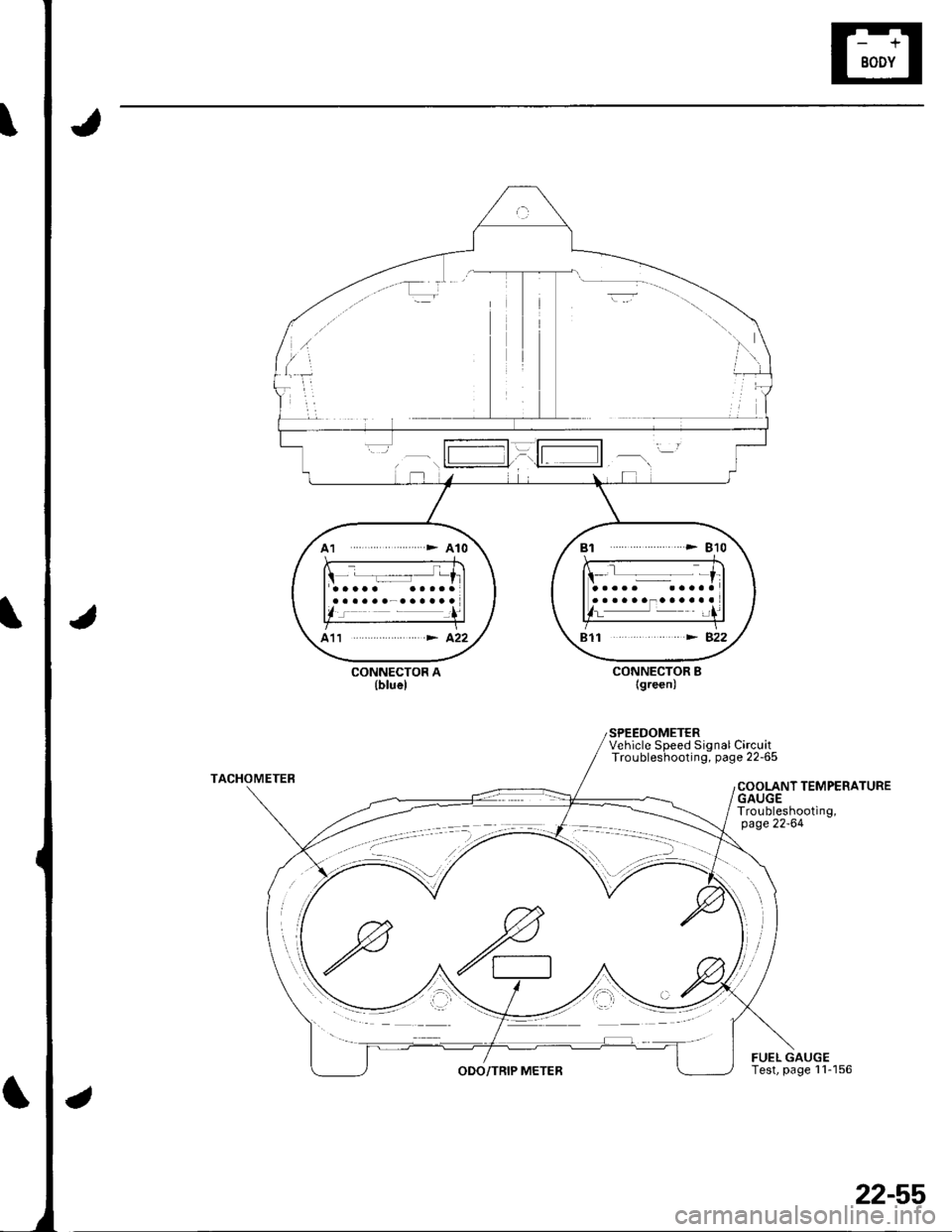
CONNECTOR A(bluelCONNECTOR BlgreenJ
SPEEDOMETERVehicle Speed Signal CircuitTroubleshooting, page 22-65
TACHOMETEB
FUEL GAUGETest, page 11-156
\7
t----/ \
i.._-
_/\
ODO/TRIP METER
22-55
Page 887 of 1139
Gauges
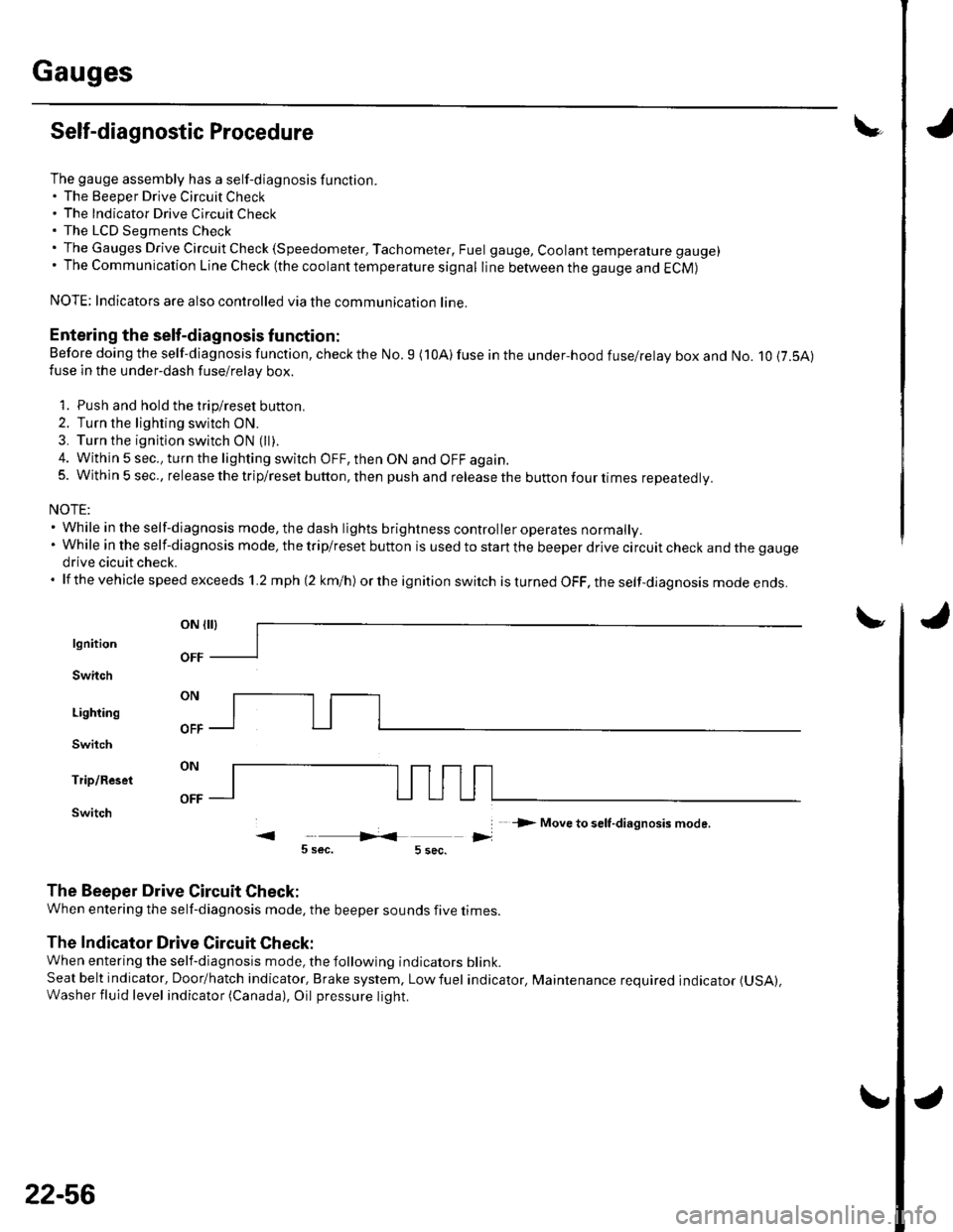
Self-diagnostic Procedure
The gauge assembly has a self-diagnosis function.. The Beeper Drive Circuit Check. The Indicator Drive Circuit ChecL. The LCD Segments Check. The Gauges Drive Circuit Check (Speedometer, Tachometer, Fuel gauge, Coolant temperature gauge). The Communication Line Check (the coolanttemperature signal line between the gauge and ECM)
NOTE: Indicators are also controlled via the communication line.
Entering the self-diagnosis f unction:
Before doing the self-diagnosis function, check the No. 9 (10A) fuse in the under-hood fuse/relay box and No. 10 {7.5A)fuse in the under'dash fuse/relay box.
1. Push and hold the trip/reset button.
2. Turn the lighting switch ON.
3. Turn the ignition switch ON (ll).
4. Within 5 sec., turn the lighting switch OFF, then ON and OFF again.5. Within 5 sec., release the trip/reset button, then push and release the button four times reDeatedlv.
NOTE:. While in the self-diagnosis mode, the dash lights brightness controller operates normally.'Whileintheself-diagnosismode,thetrip/resetbuttonisusedtostartthebeeperdrivecircuitcheckandthegauge
drive cicuit check.. lf the vehicle speed exceeds 1.2 mph 12 km/h) orthe ignition switch is tu rned OFF, the self,diag nosis mode ends.
oN flrl
lgnition
Switch
Lighting
Switch
Trip/Reset
Switch-> Move to selt-diagnosis mode.
5 sec.5 sec.
The Beeper Drive Circuit Check:
When entering the self-diagnosis mode, the beeper sounds five times
The Indicator Drive Circuit Check:
When entering the self-diagnosis mode, the following indicators blink.
Seat belt indicator, Door/hatch indicator, Brake system, Lowfuel indicator, Maintenance required indicator (USA),
Washer fluid level indicator (Canada), Oil pressure light.
v
OFF
22-56