check oil HONDA CIVIC 2003 7.G User Guide
[x] Cancel search | Manufacturer: HONDA, Model Year: 2003, Model line: CIVIC, Model: HONDA CIVIC 2003 7.GPages: 1139, PDF Size: 28.19 MB
Page 120 of 1139
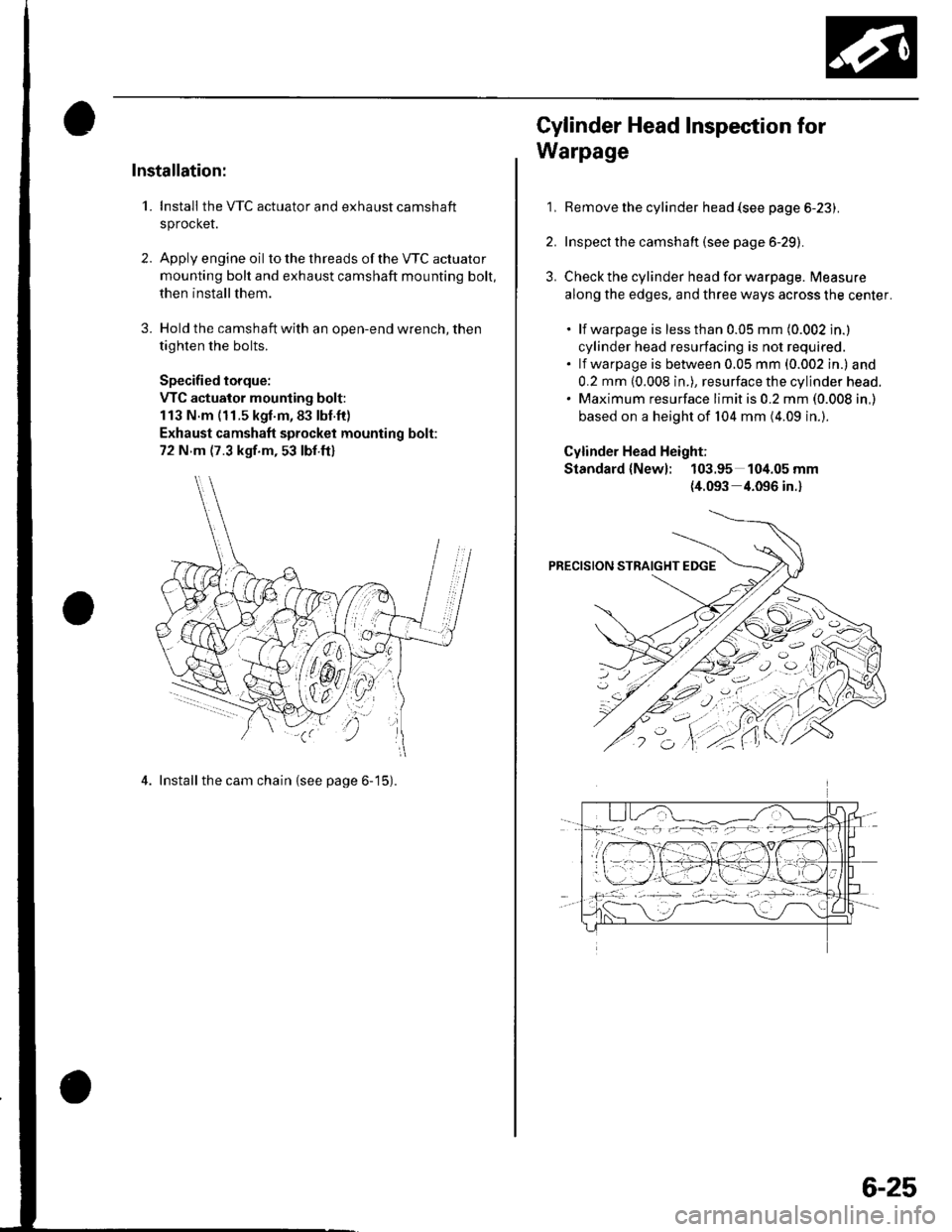
Installation:
1. Install the VTC actuator and exhaust camshaft
sprocket.
2. Apply engine oil to the th reads of the VTC actuato r
mounting bolt and exhaust camshaft mounting bolt,
then install them.
3. Hold the camshaft with an open-end wrench, then
tighten the bolts.
Specified torque:
VTC actuator mounting bolt:
113 N.m (11.5 kgl.m,83 lbl.ft)
Exhaust camshaft sprocket mounting bolt:
72 N m (7.3 kgf.m, 53 lbf.ft)
4. Install the cam chain {see page 6-15).
1,
Cylinder Head Inspection for
Warpage
Remove the cylinder head {see page 6-23).
Inspect the camshaft (see page 6-29).
Check the cylinder head for warpage. Measure
along the edges, and three ways across the center.
. lf warpage is less than 0.05 mm (0.002 in.)
cylinder head resurfacing is not required.. lf warpage is between 0.05 mm (0.002 in.) and
0.2 mm (0.008 in.), resurface the cylinder head.. Maximum resurface limit is 0.2 mm (0.008 in,)
based on a height of 104 mm (4.09 in.).
Cylinder Head Height;
Standard {New}: 103.95 104.05 mm
{4.093 4.096 in.}
6-25
Page 123 of 1139
Cylinder Head
1.
2.
Rocker Arms and Shafts Inspection
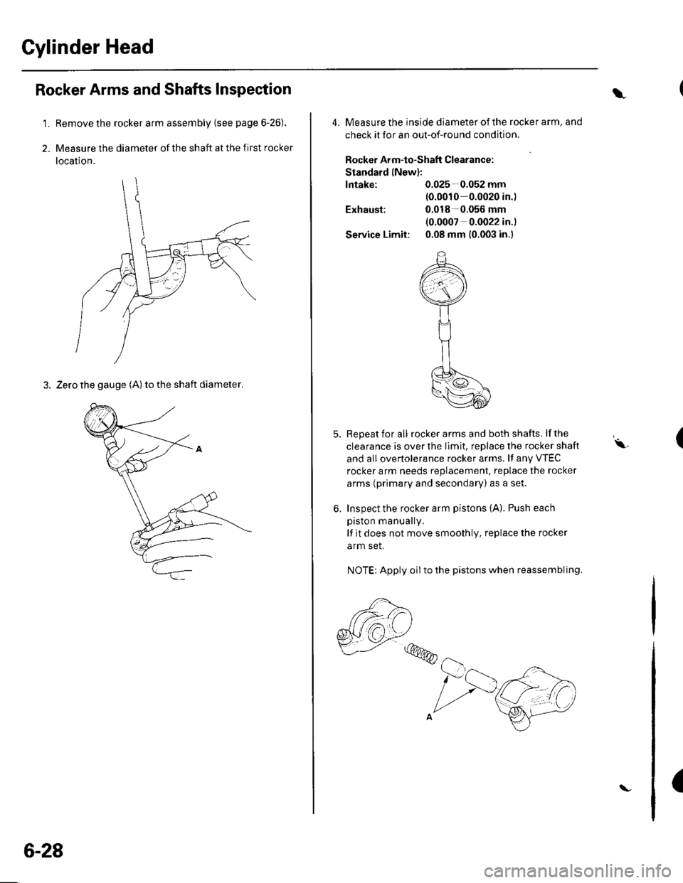
Remove the rocker arm assembly (see page 6-26).
Measure the diameter of the shaft at the first rocker
location.
3. Zero the gauge (A) to the shaft diameter.
6-28
\
4. Measure the inside diameter ofthe rocker arm, and
check it for an out-of-round condition.
Rocker Arm-to-Shaflt Clearance:
Standard lNew):
lntake: 0.025 0.052 mm(0.0010 0.0020 in.)
Exhaust: 0.018 0.056 mm
(0.0007 0.0022 in.)
Service Limit: 0.08 mm (0.003 in.)
5. Repeat for all rockerarms and both shafts. lfthe
clearance is over the Ilmit. replace the rocker shaft
and all overtolerance rocker arms. lf any VTEC
rocker arm needs replacement, replace the rocker
arms (primary and secondary) as a set.
6. Inspect the rocker arm pistons {A}. Push each
piston manually.
lf it does not move smoothly, replace the rocker
arm set.
NOTE: Apply oil to the pistons when reassembling.
,,,@@
(\.
(
Page 125 of 1139
Cylinder Head
Camshaft Inspection (cont'dl
1.
9.
Unscrew the camshaft holder bolts two turns at a
time, in a crisscross pattern. Then remove the
camshaft holders from the cylinder head.
Lift the camshafts out of the cylinder head, wipe
them clean. then inspect the lift ramps. Replace the
camshaft if any lobes are pitted, scored, or
excessively worn,
Clean the camshaft journal surfaces in the cylinder
head, then set the camshafts back in place. Place a
plastigage strip across each journal.
Install the camshaft holders, then tighten the bolts
to the specified torque as shown in step 2.
Remove the camshaft holders. Measure the widest
portion of plastigage on each journal.
. lf the camshaft-to-holder clearance is within
limits, go to step 1 1.. lf the camshaft-to-holder clearance is beyond the
service limit and the camshaft has been replaced,
replace the cylinder head.. lf the camshaft-to-holder clearance is beyond the
service limit and the camshaft has not been
replaced, go to step 10.
Camshaft-to-Holder Oil Clearance:
Standard (New):
No. 1 Journal:
No.2,3,4,5 Journals:
Service Limit:
0.030 0.069 mm
{0.001 0.003 in-)
0.060*0.099 mm
{0.002 0.004 in.)
0.15 mm {0.006 in.)
6-30
\-
{\
10. Check the total runout with the camshaft supported
on V-blocks,
.lfthetotal runout of the camshaft is within the
service limit, replace the cylinder head.. lf the total runout is beyond the service limit,
replace the camshaft and recheck the camshaft-
to-holder oil clearance. lf the oil clearance is still
beyond the service limit, replace the cylinder
neao.
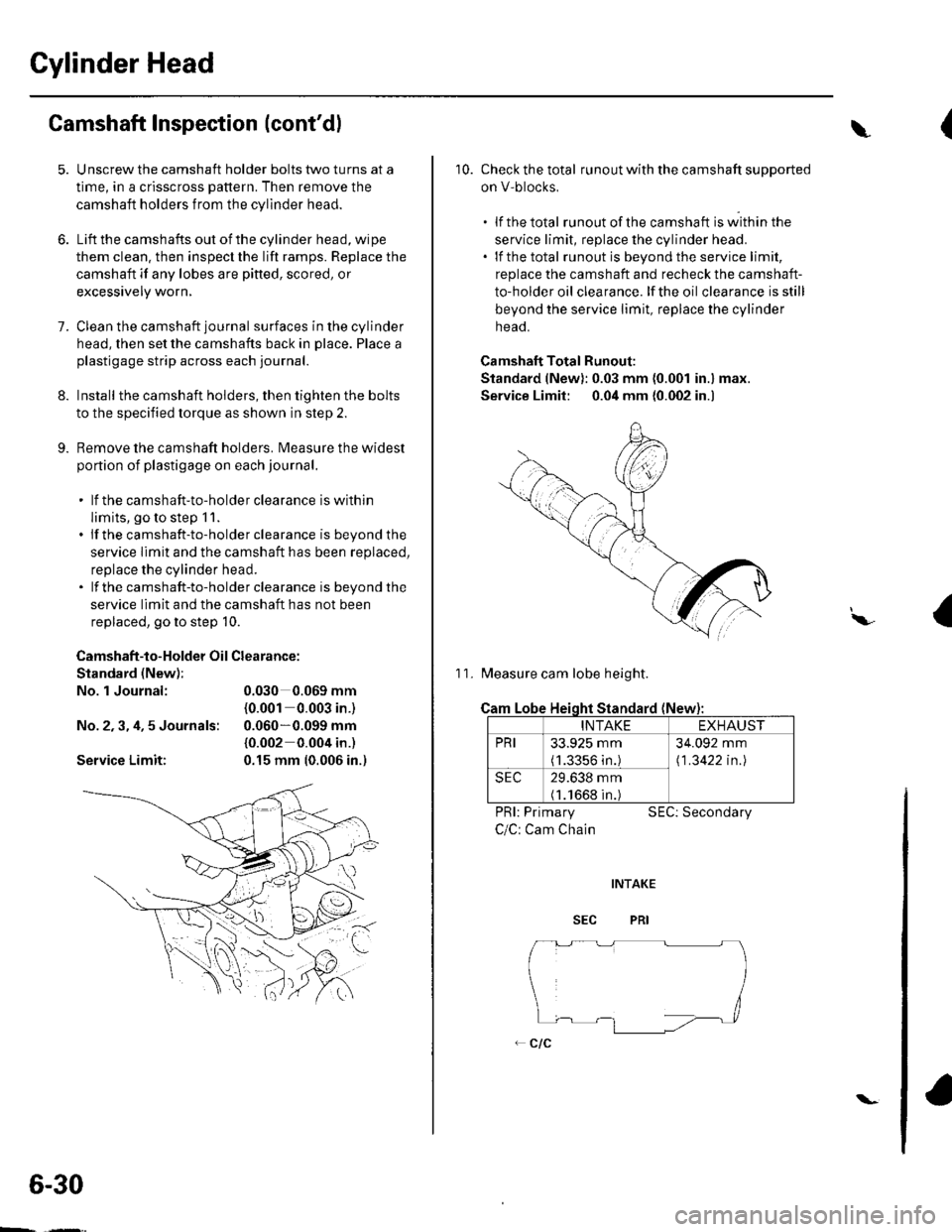
Camshaft Total Runout:
Standard (New): 0.03 mm (0.001 in.) max.
Service Limit: 0.04 mm {0.002 in.)
11. Measure cam lobe height.
Cam
PRI: Primary
C/C: Cam Chain
SEC: Secondary
I\,
Lobe Heioht Standard (New
INTAKEEXHAUST
PRI33.925 mm(1.3356 in.)
34.092 mm
\1 .3422 in.l
SEC29.638 mm(1.1668 in.)
Page 129 of 1139
Cylinder Head
Valve Guide Replacement (cont'dl
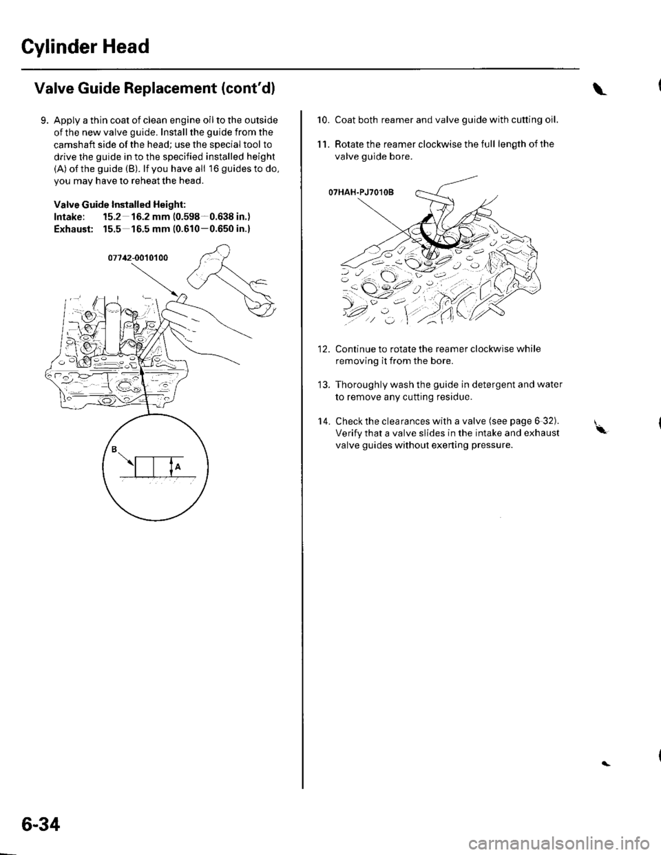
Apply a thin coat of clean engine oil to the outside
of the new valve guide. Install the guide from the
camshaft side of the head; use the special tool to
drive the guide in to the specified installed height
(A) o{the guide (B). lf you have all 16 guidesto do,
you may have to reheat the head.
Valve Guide Installed Height:
Intake: 15.2 16.2 mm (0.598-0.638 in.)
Exhaust: 15.5 16.5 mm (0.610-0.650 in.)
6-34
\
10.Coat both reamer and valve guide with cutting oil.
Rotate the reamer clockwise the full length of the
valve guide bore.
O7HAH.PJ7O1OB
Continue to rotate the reamer clockwise while
removing it from the bore.
Thoroughly wash the guide in detergent and water
to remove any cutting residue.
Check the clearances with a valve (see page 6 32).
Verify that a valve slides in the intake and exhaust
valve guides without exening pressure.
11.
14.
'-\
Page 132 of 1139
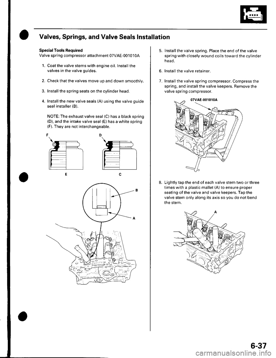
Valves, Springs, and Valve Seals Installation
Special Tools Required
Valve spring compressor attachment 07VAE-00101 0A
1. Coat the valve stems with engine oil. lnstall the
valves in the valve guides.
2. Check that the valves move up and down smoothly.
Installthe spring seats on the cylinder head.
Install the new valve seals (A) using the valve guide
seal installer (B).
NOTE: The exhaust valve seal (C) has a black spring(D), and the intake valve seal (E) has a white spring(F). They are not interchangeable.
6.
lnstallthe valve spring. Place the end ofthe valve
spring with closely wound coils toward the cylinder
n eao.
Install the valve retainer.
Installthe valve spring compressor, Compress the
spring, and install the valve keepers. Remove the
valve spring compressor.
Lightly tap the end of each valve stem two or three
times with a plastic mallet (A) to ensure proper
seating of the valve and valve keepers. Tap the
valve stem only along its axis so you do not bend
the stem.
7.
6-37
Page 138 of 1139
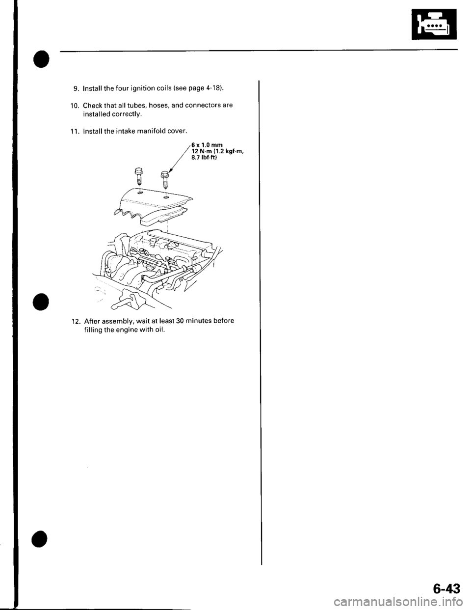
9.
10.
Install the four ignition coils (see page 4-'18).
Check that all tubes, hoses, and connectors are
installed correctly.
lnstallthe intake manifold cover.11.
6x 1,0 mm'12 N.m {1.2 kgf m.8.7 tbf.ftl
12. After assemblv, wait at least 30 minutes before
filling the engine with oil.
6-43
Page 143 of 1139
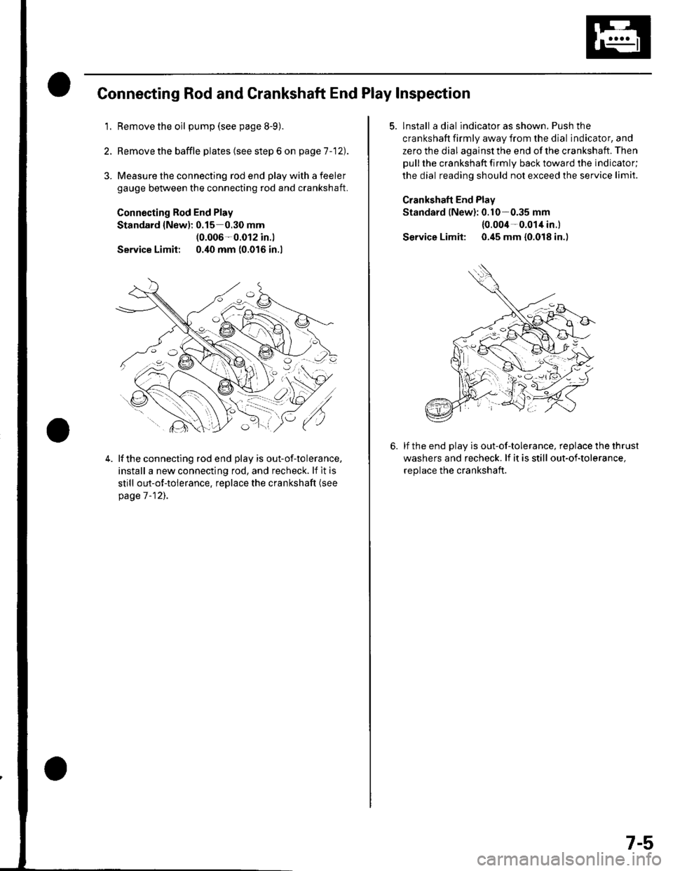
Connecting Rod and Crankshaft End Play Inspection
1.Remove the oil pump (see page 8-9).
Remove the baffle plates (see step 6 on page 1 -12).
3. Measure the connecting rod end play with a feeler
gauge between the connecting rod and crankshaft.
Connecting Rod End Play
Standard {New): 0.15 0.30 mm(0.006-0.012 in.l
Service Limit 0.40 mm (0.016 in.l
4.lf the connecting rod end play is out-of-tolerance,
install a new connecting rod, and recheck. lf it is
still out-of-tolerance, replace the crankshaft (see
page 7 -12],.
5. lnstall a dial indicator as shown. Push the
crankshaft firmly away from the dial indicator, and
zero the dial against the end of the crankshaft. Then
pull the crankshaft firmly back toward the indicator;
the dial reading should not exceed the service limit.
Crankshaft End Plav
Standard lNew): 0.10-0.35 mm
{0.004-0.014 in.l
Service Limit: 0.45 mm {0.018 in.)
lf the end play is out-of-tolerance, replace the thrust
washers and recheck. lf it is still out-of-tolerance,
replace the crankshaft.
7-5
Page 144 of 1139
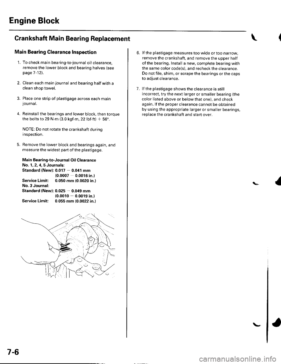
Engine Block
Crankshaft Main Bearing Replacement
Main Bearing Clearance Inspection
1. To check main bea ring-to-jou rna I oil clearance.
remove the lower block and bearing halves (see
page 1 -12)..
2, Clean each main journal and bearing half witha
clean shop towel.
3. Place one strip of plastigage across each main
lou rnal.
4. Reinstallthe bearings and lower block, then torque
the bolts to 29 N.m {3.0 kgf.m,22 lbf.ft) + 56'.
NOTE: Do not rotate the crankshaft during
Inspeclton.
5. Remove the lower block and bearings again, and
measure the widest part of the plastigage.
Main Bearing-to-Journal Oil Clearance
No. 1,2, 4,5 Journals:
Standard (New): 0.017 0.041 mm
Service Limit:
No.3 Journal:
10.0007 0.0016 in.l
0.050 mm {0.0020 in.)
Standard {Newl: 0.025 - 0.049 mm(0.0010 0.0019 in.)
Service Limit: 0.055 mm (0.0022 in.l
7-6
\.
6. lf the plastigage measures too wide or too narrow,
remove the crankshaft. and remove the upper half
ofthe bearing. Install a new, complete bearing with
the same color code{s), and recheck the clearance.
Do not file, shim, or scrape the bearings or the caps
to adjust clearance.
7. lf the plastigage shows the clearance is still
incorrect, try the next larger or smaller bearing (the
color listed above or below that one), and check
again. lf the proper clearance cannot be obtained
by using the appropriate larger or smaller bearings,
replace the crankshaft and start over.
Page 147 of 1139
8.
9.
lf the plastigage measures too wide or too narrow,
remove the upper half of the bearing, install a new,
complete bearing with the same color code(s), and
recheck the clearance. Do not file. shim, or scrape
the bearings or the caps to adjust clearance.
lf the plastigage shows the clearance is still
incorrect, try the next larger or smaller bearing (the
color listed above or below that one), and check
clearance agaln. lf the proper clearance cannot be
obtained by using the appropriate larger or smaller
bearing, replace the crankshaft and stan over.
Rod Bearing Selection
1. Inspect each connecting rod for cracks and heat
damage.
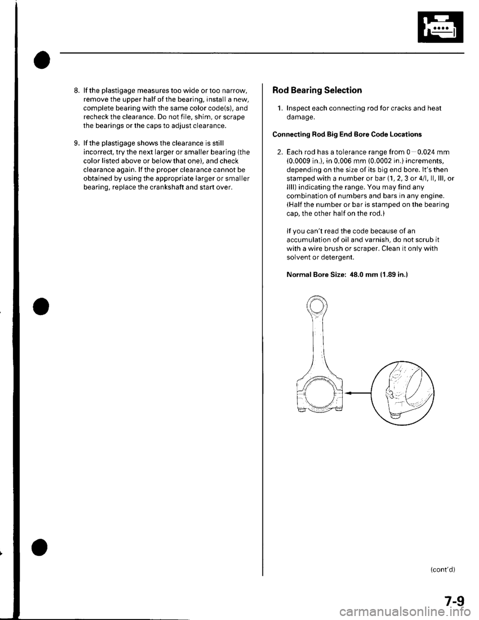
Connecting Rod Big End Eore Code Locations
2. Each rod has a tolerance range from 0 0.024 mm
(0.0009 in.), in 0.006 mm (0.0002 in.) increments,
depending on the size of its big end bore. lt's then
stamped with a number or bar (1, 2,3 or 4/1, ll,lll, ol
llll) indicating the range. You may find any
combination of numbers and bars in any engine.(Half the number or bar is stamped on the bearing
cap, the other half on the rod.)
lf you can't read the code because of an
accumulation of oil and varnish. do not scrub it
with a wire brush or scraper. Clean it only with
solvent or detergent.
Normal Bore Size: 48.0 mm 11.89 in.l
(cont'd)
7-9
Page 159 of 1139
Piston Ring Replacement
1. Remove the piston {rom the cylinder block (see
page 7 -121.
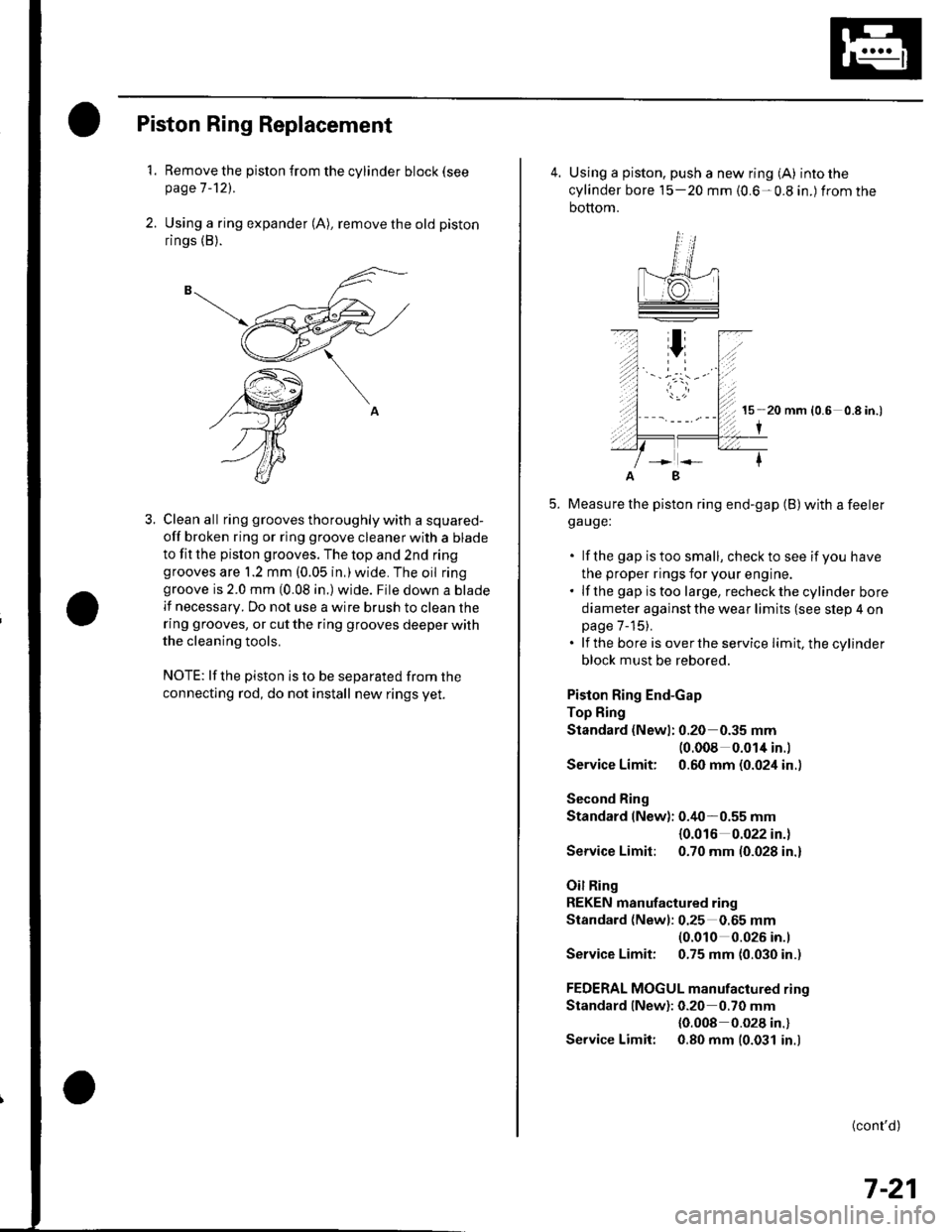
2. Using a ring expander (A), remove the old piston
rings (B).
3. Clean all ring grooves thoroughly with a squared-
off broken ring or ring groove cleaner with a blade
to fit the pislon grooves. The top and 2nd ringgrooves are 1.2 mm (0.05 in,)wide. The oil ringgroove is 2.0 mm (0.08 in.) wide. File down a blade
lf necessary. Do not use a wire brush to clean the
ring grooves, or cut the ring grooves deeper with
the cleaning tools.
NOTE: lf the piston is to be separated from the
connecting rod, do not install new rings yet.
4. Using a piston, push a new ring (A) into the
cylinder bore 15-20 mm {0.6-0.8 in.) from the
bottom.
15 20 mm (0.6 0.8 in.)
I
Measure the piston ring end-gap (B) with a feelerga uge:
. lf the gap istoo small, checkto see if you have
the proper rings for your engine.. lf the gap istoo large, recheckthecylinder bore
diameter against the wear limits (see slep 4 onpage 7-15).. lf the bore is overthe service limit, the cylinder
block must be rebored.
Piston Ring End-Gap
Top Fing
Standard (Newl: 0.20 0.35 mm(0.008 0.014 in.l
Service Limit: 0.60 mm (0.024 in..
Second Ring
Standard (New): 0.40-0.55 mm
{0.016 0.022 in.)
Service Limit: 0.70 mm (0.028 in.)
Oil Ring
REKEN manufactured ring
Standard (Newl: 0.25 0.65 mm(0.010 0.026 in.l
Service Limit: 0.75 mm (0.030 in.)
FEDERAL MOGUL manufactured rino
Standard lNew): 0.20 0.70 mm
{0.008 0.028 in.}
Service Limit: 0.80 mm (0.031 in.)
B
(cont'd)
7-21