check oil HONDA CIVIC 2003 7.G Owner's Manual
[x] Cancel search | Manufacturer: HONDA, Model Year: 2003, Model line: CIVIC, Model: HONDA CIVIC 2003 7.GPages: 1139, PDF Size: 28.19 MB
Page 161 of 1139
Piston Installation
lf the crankshaft is already installed
1. Setthe crankshaftto bottom dead center (BDC) for
each cylinder.
2. Remove the connecting rod caps, then install the
ring compressor, and check that the bearing is
securely in place,
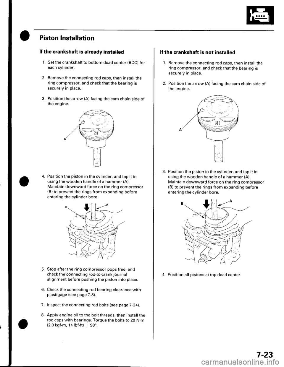
3. Position the arrow {A) facing the cam chain side of
rne engtne.
Position the piston in the cylinder, and tap it in
using the wooden handle of a hammer (A).
N4aintain downward force on the ring compressor(B) to prevent the rings from expanding before
entering the cylinder bore.
Stop after the ring compressor pops free, and
check the connecting rod-to-crank journal
alignment before pushing the piston into place.
Check the connecting rod bearing clearance withplastigage (see page 7-8).
lnspect the connecting rod bolts (see page 7 241.
Apply engine oil to the bolt threads, then install the
rod caps with bearings. Torque the bolts to 20 N.m
{2.0 kgf m, 14 lbf ft) + 90'.
6.
7.
2.
1.
lf the crankshaft is not installed
Remove the connecting rod caps. then install the
ring compressor, and check that the bearing is
securely in place.
Position the arrow (A)facing the cam chain side of
Ine engrne.
Position the piston in the cylinder, and tap it in
using the wooden handle of a hammer (A),
Maintain downward force on the ring compressor(B) to prevent the rings from expanding before
entering the cylinder bore.
4. Position all pistons attop dead center.
\--lno n\-.--l. ^u t
>-*/zi
.,.'_\pf{
wr
(( 'V,/ :
7-23
Page 162 of 1139
Engine Block
Connecting Rod Bolt Inspection
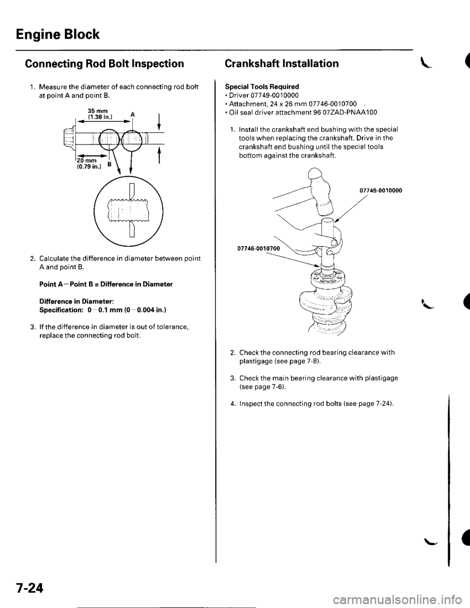
Measure the diameter of each connectinq rod bolt
at Doint A and ooint B.
35 mm
Calculate the difference in diameter between point
A and point B.
Point A-Point B = Difference in Diameter
Diflerence in Diameter:
Specification: 0 0.1 mm (0 0.004 in.)
lf the difference in diameter is out of tolerance,
replace the connecting rod bolt.
1.
3,
mm
7-24
\-
Crankshaft Installation
Special Tools Bequired. Driver 07749-0010000. Attachment, 24 x 26 mm 07746-0010700. Oil seal driver attachment 96 o7ZAD-PNAAl00
1. Install the crankshaft end bushing with the special
tools when replacing the crankshaft. Drive in the
crankshaft end bushing until the special tools
bottom aqainst the crankshaft.
07749-0010000
07746-00'l
Check the connecting rod bearing clearance with
plastigage {see page 7-8).
Check the main bearing clearance with plastigage
(see page 7-6).
lnspectthe connecting rod bolts (see pageT-241.
(
I\-(
4.
a
Page 170 of 1139
Engine Lubrication
Oil Pressure Switch Test
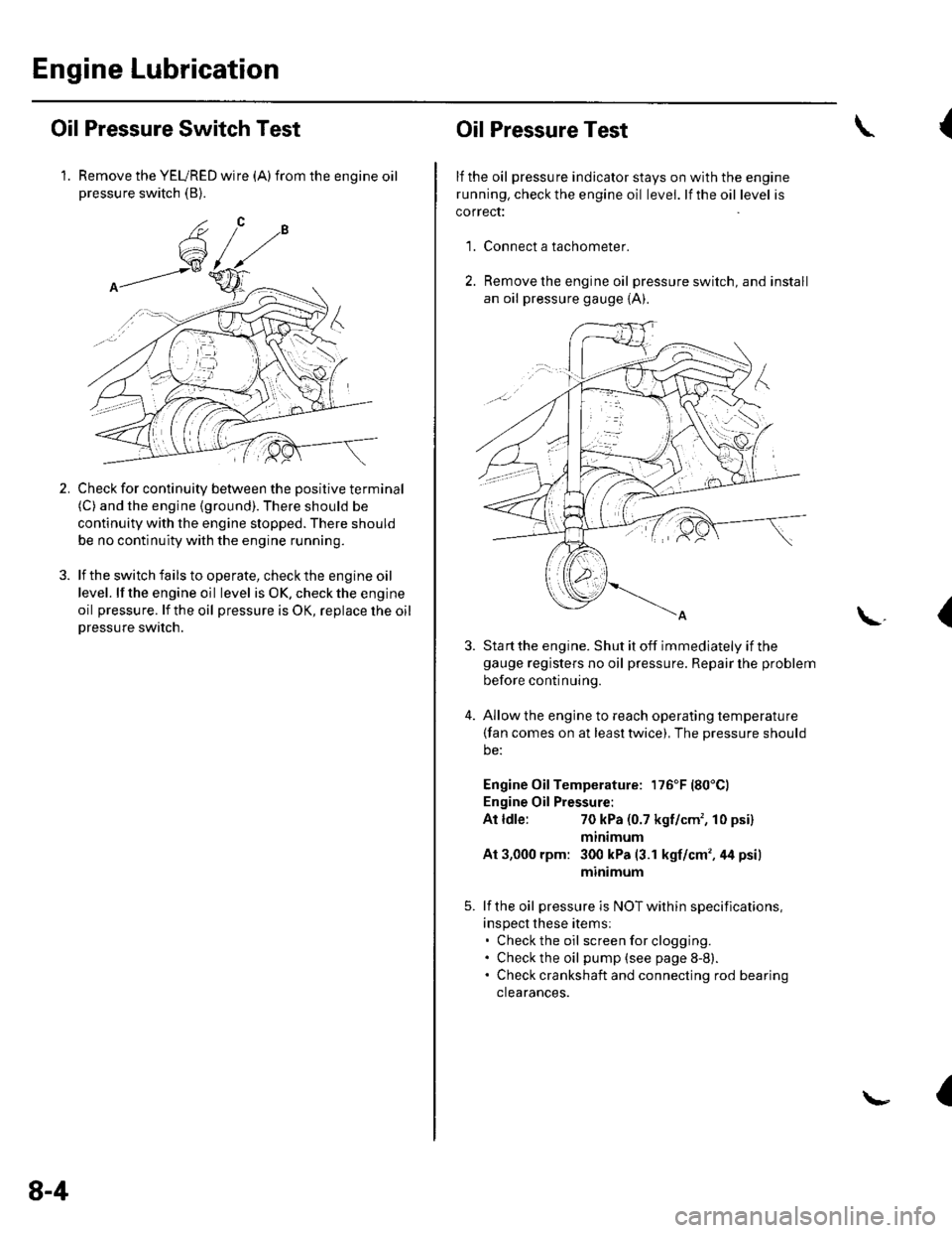
1. Remove the YEURED wire (A)from the engine oilpressure switch (B).
Check for continuity between the positive terminal(C) and the engine (ground). There should be
continuity with the engine stopped. There should
be no continuity with the engine running.
lf the switch fails to operate, check the engine oil
level. lf the engine oil level is OK. check the engine
oil pressure. lf the oil pressure is OK, replace lhe oil
Dressure switch.
2.
8-4
Oil Pressure Test
lf the oil pressure indicator stays on with the engine
running. check the engine oil level. lf the oil level is
correct:
Connect a tachometer.
Remove the engine oil pressure switch, and install
an oil pressure gauge {A).
{
'1.
\.(
4.
Sta rt the engine. Shut it off immediately if thegauge registers no oil pressure. Repair lhe problem
before continuing.
Allow the engine to reach operating temperature(fan comes on at least twice), The pressure should
be:
Engine Oil Temperature: 176'F (80'Cl
Engine Oil Pressure:
At ldle:70 kPa (0.7 kgf/cm', 10 psi)
mtntmum
At 3,000 rpm: 300 kPa (3.1 kgf/cm',44 psi)
minimum
lf the oil pressure is NOT within specifications,
inspect these items:. Check the oil screenforclogging.. Check the oil pump (see page 8-8).. Check crankshaft and connecting rod bearing
clearances.
I
Page 171 of 1139
Engine Oil Replacement
Warm up the engine.
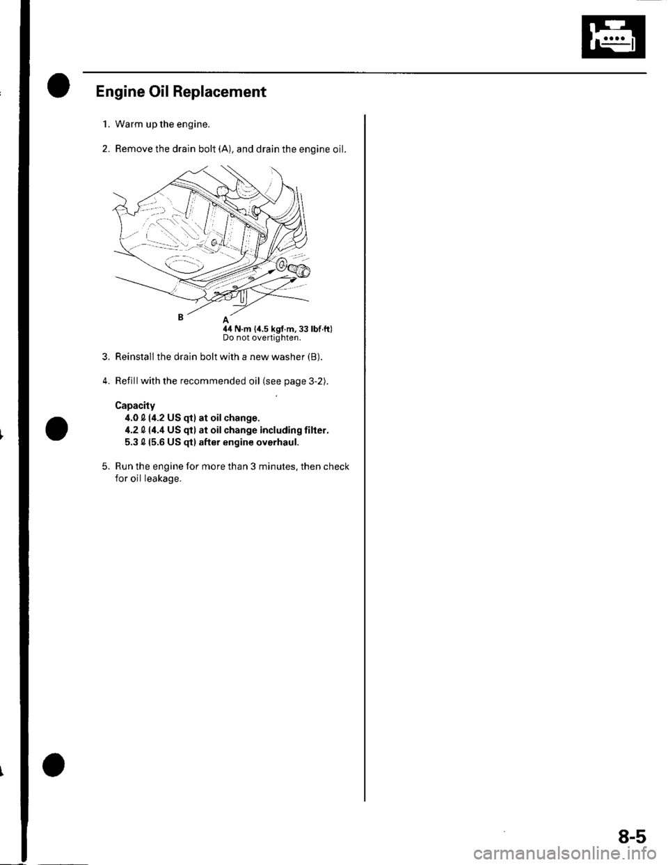
Remove the drain bolt (A), and drain the engine oil.
nA
44 N.m {i1.5 kgf.m,33 lbf.ft)Do not overtighten.
Reinstall the drain bolt with a new washer (B).
Refillwith the recommended oil (see page 3-2).
Capacity
4.0 0 (4.2 US qt) at oilchange.
4.2 014.4 US qt) at oilchange including filter.
5.3 015.6 US $) after engine overhaul.
Run the engine for more than 3 minutes. then check
for oil leakage.
1.
2.
3.
5.
8-5
Page 172 of 1139
Engine Lubrication
Engine Oil Filter Replacement
Special Tool Fequired
Oil filter wrench 07HAA-PJ70100
Engine Oil Filter (3/4-turn type)
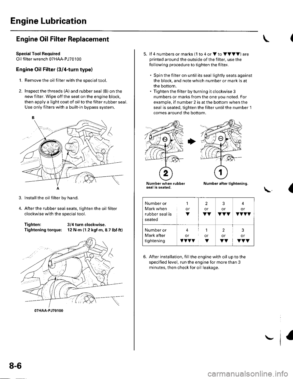
1. Remove the oil filterwiththesDecial tool.
2. Inspect the threads {A) and rubber seal (B) on the
new filter. Wipe off the seat on the engine block,
then apply a light coat of oil to the filter rubber seal.
Use only filters with a built-in bypass system.
Installthe oilfilter by hand.
After the rubber seal seats, tighten the oil filter
clockwise with the special tool.
Tighten: 3/4 turn clockwise.
Tightening torque: 12 N.m (r.2 kgf.m,8.7 lbf.ft)
07HAA-PJ70100
8-6
\,
5. lf 4 numbers or marks (1 to 4 or V to VVVV) are
printed around the outside of the filter, use the
following procedure to tighten the filter.
. Spin the filter on until its seal lightly seats against
the block, and note which number or mark is at
the bottom.. Tighten the filter by turning it clockwise 3
numbers or marks from the one you noted. For
example, if number 2 is at the bottom when the
seal is seated, tighten the filter until the number 1
comes around the bottom.
Number when rubberseal is seated.Number after tightening.
(\..
6. After installation, fill the enginewith oil uptothe
specified level, run the engine for more than 3
minutes, then check for oil leakage.
Number or
Mark when
rubber seal is
1
or
V
2
or
VV
3
or
VVV
4
or
VVVV
Number or
Mark after
tightening
41
or or
vvvv. v
2
or
VV
3
or
VVV
Page 176 of 1139
Engine Lubrication
Oil Pump Overhaul {cont'dl
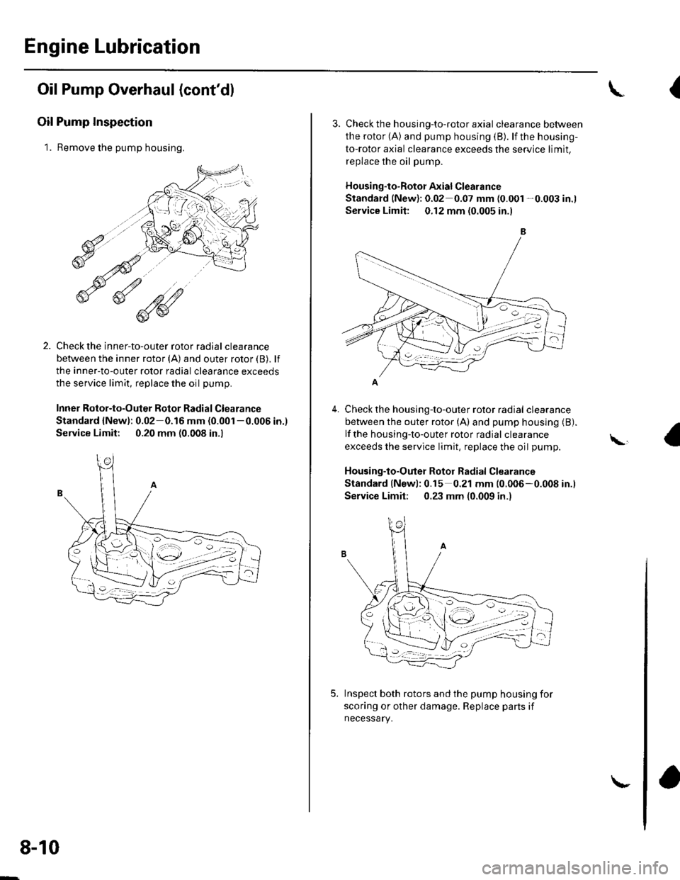
Oil Pump Inspection
1. Remove the pump housing.
Check the inner-to-outer rotor radial clearance
between the inner rotor (A) and outer rotor {B). lf
the inner-to-outer rotor radial clearance exceeds
the service limit, replace the oil pump.
Inner Rotor-to-Outer Botor Radial Clearance
Standard {New): 0.02 0.16 mm (0.001 -0.006 in.)
Service Limit: 0.20 mm (0.008 in.,
1'[1e-\1.-,-2
1 'a - :.: ,-'r'
8-10
\-
{
4.
3. Check th e h ousing-to-roto r axia I clearance between
the rotor (A) and pump housing (B). lf the housing-
to-rotor axial clearance exceeds the service limit.
replace the oil pump.
Housing"to-Rotor Axial Clearance
Standard (New): 0.02 0.07 mm (0.001 -0.003 in.l
Service Limit: 0.12 mm (0.005 in.l
Check the housing-to-outer rotor radial clearance
between the outer rotor (A) and pump housing (B).
lf the housing-to-outer rotor radial clearance
exceeds the service limit, replace the oil pump.
Housing-to-Outer Rotor Radial Clearance
Standard lNewl: 0.15 0.21 mm (0.006-0.008 in.l
Service Limit; 0.23 mm (0.009 in.)
Inspect both rotors and the pump housing for
scoring or other damage. Replace parts if
necessary.
\,
Page 179 of 1139
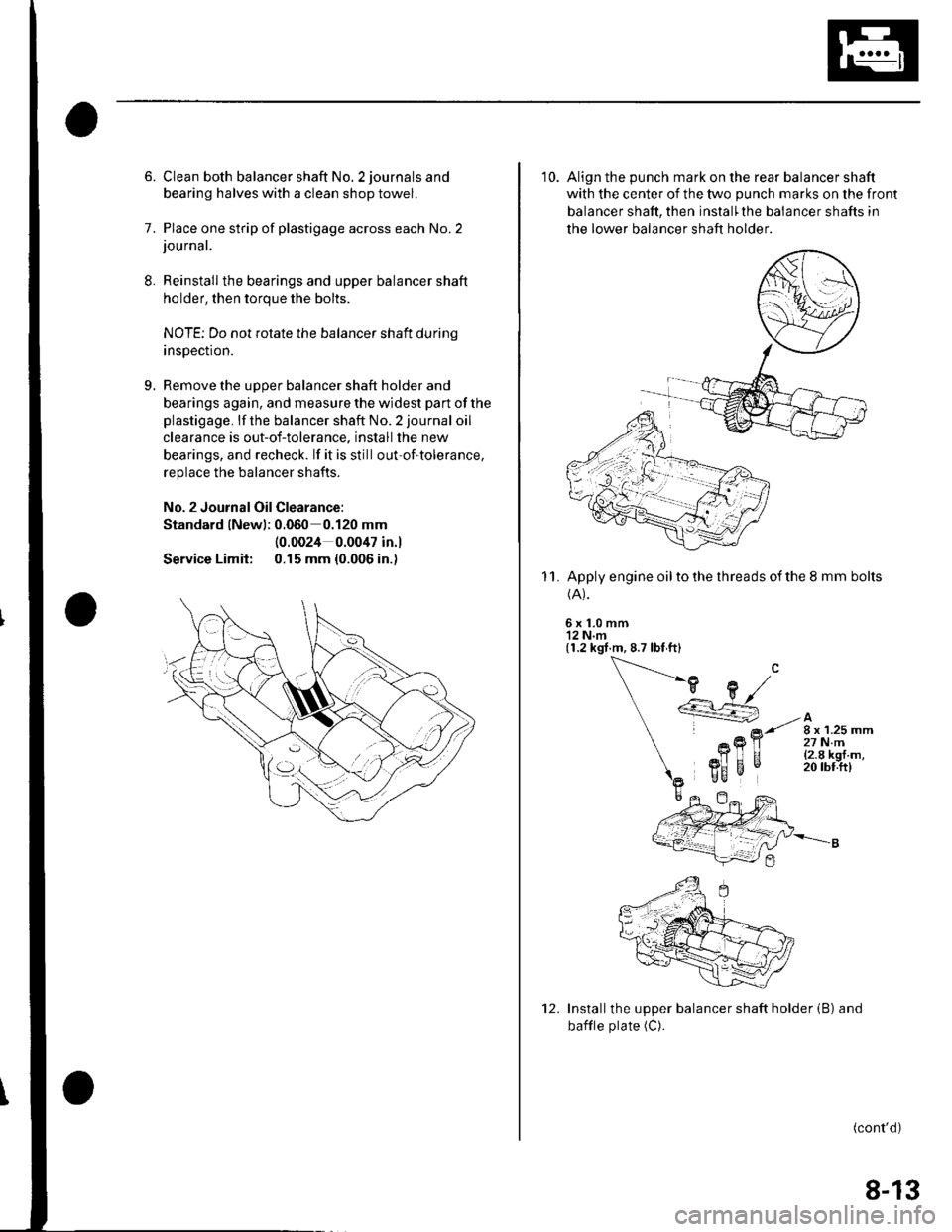
8.
9.
6. Clean both balancer shaft No. 2 journals and
bearing halves with a clean shop towel.
7. Place one strip of plastigage across each No.2journal.
Reinstall the bearings and upper balancer shaft
holder, then torque the bolts.
NOTE; Do not rotate the balancer shaft durinq
insDection.
Remove the uooer balancer shaft holder and
bearings again, and measure the widest part of the
plastigage. lf the balancer shaft No. 2 journal oil
clearance is out-of-tolerance. install the new
bearings, and recheck. lf it is still out-of-tolerance,
replace the balancer shafts.
No. 2 Journal Oil Clearance:
Standard lNewl; 0.060 0.120 mm
Service Limit:
(0.0024 0.0047 in.l
0.15 mm {0.006 in.)
10. Align the punch mark on the rear balancer shaft
with the center of the two punch marks on the front
balancer shaft, then install'the balancer shafts in
the lower balancer shaft holder
Apply engine oil to the threads of the 8 mm bolts(A).
6x1.0mm'12 N.m(1.2 kgt.m, 8.7 lbt ft)
11.
Installthe upper balancer shaft holder (B) and
bafile plate (C).
(cont'd)
12.
8-13
Page 217 of 1139
Fuel and Emissions Systems
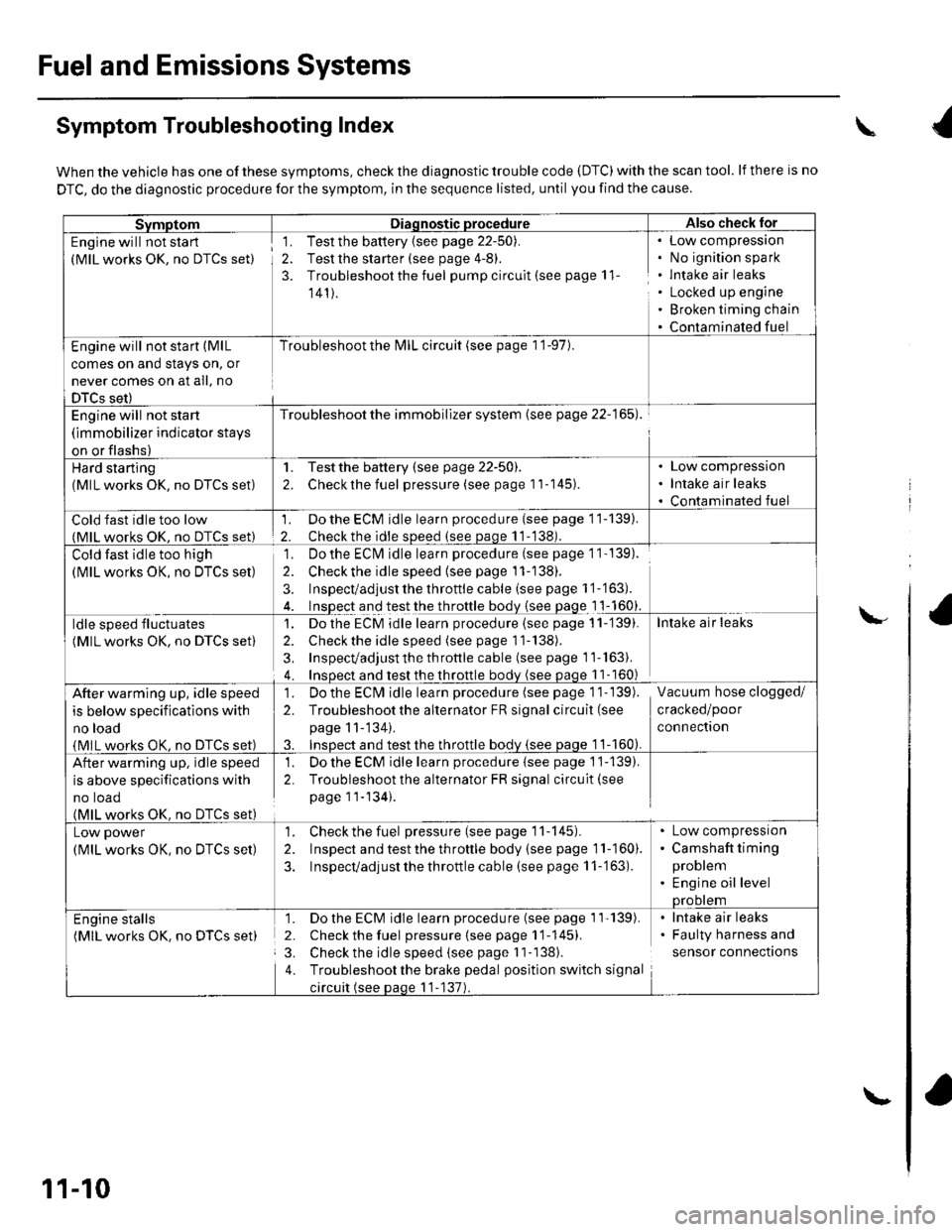
Symptom Troubleshooting Index
When the vehicle has one of these symptoms, check the diagnostic trouble code (DTC) with the scan tool. lf there is no
DTC, do the diagnostic procedure for the symptom, in the sequence listed, until you find the cause.
SvmotomDiaqnostic procedureAlso check lor
Engine will not sta rt
(MlL works OK, no DTCS set)
1. Test the battery {see page 22-50).
2. Test the starter (see page 4-8).
3. Troubleshoot the fuel pump circult (see page 11
141).
Low compressron
No ignition spark
lntake air leaks
Locked up engine
Broken timing chain
Contaminated fuel
Engine will not start (MlL
comes on and stays on, or
never comes on at all, no
DTCS set)
Troubleshoot the l\4lL circuit (see page 1 '1-97).
Engine will not start
(immobilizer indicator stays
on or flashs)
Troubleshoot the immobilizer system (see page 22-165).
Hard starting(MlL works OK, no DTCS set)
1. Testthe battery (see page 22-50).
2. Checkthe fuel pressure (see page 11-145).
Low compression
Intake air leaks
Contaminated fuel
Cold fast idle too low(MlL works OK. no DTCS set)
1. Do the ECM idle learn procedure (see page 11-139).
2. Checkthe idle sDeed (see paqe 11-138).
Cold fast idle too high
(MlL works OK, no DTCS set)
Do the ECI\4 idle learn procedure (see page 1 1- 139).
Checkthe idle speed {see page 11-138).
Inspect/adjust the throttle cable (see page 1 '1-'163).
Inspect and test the throttle body {see page 1 1-160}.
']�
2.
3.
ldle speed fluctuates
(MlL works OK, no DTCS set)
1. Dothe ECM idle learn procedure (see page 11-'139).
2. Check the idle speed (see page 11-138).
3, Inspecvadjust th e throttle cable (see page 11''163).
4. Insoect and test the throttle bodv (see paqe 11- 160)
Intake air leaks
After warming up, idle speed
is below specifications with
no load
{MlL works OK, no DTCS set)
1. Do the ECIVI idle learn procedure (see page 1 1- 139).
2. Troubleshootthe alternator FR signal circuit (see
page 11-'134).
3. InsDect and test the throttle bodv {see paqe 1 1-160).
Vacuum hose clogged/
cracked/poor
connectron
After warming up, idle speed
is above specifications with
no toao(MlL works OK. no DTCS set)
1. Do the ECM idle learn procedure {see page 1'j-139).
2. Troubleshoot the alternator FR signal circuit(see
page 11-134).
Low power
(MlL works OK, no DTCS set)
1. Check the fuel pressure(seepagell-145).
2. Inspect and test the th roftle body (see page 11-160).
3. Inspecvadjust the throttle cable (see page 11-'163).
Low compressron
Camshaft timing
problem
Engine oil levelprootem
Engine stalls(MlL works OK. no DTCS set)
1. Do the ECM idle learn procedure (see page 1'l'139).
2. Check the fuel pressure{seepagell-145).
3. Check the idle speed (see page I 1-138).
4. Troubleshootthe brake pedal position switch signal
circuit (see paqe 11-137).
lntake air leaks
Faulty harness and
sensor connections
\
\-
11-10
\-
Page 279 of 1139
PGM-FI System
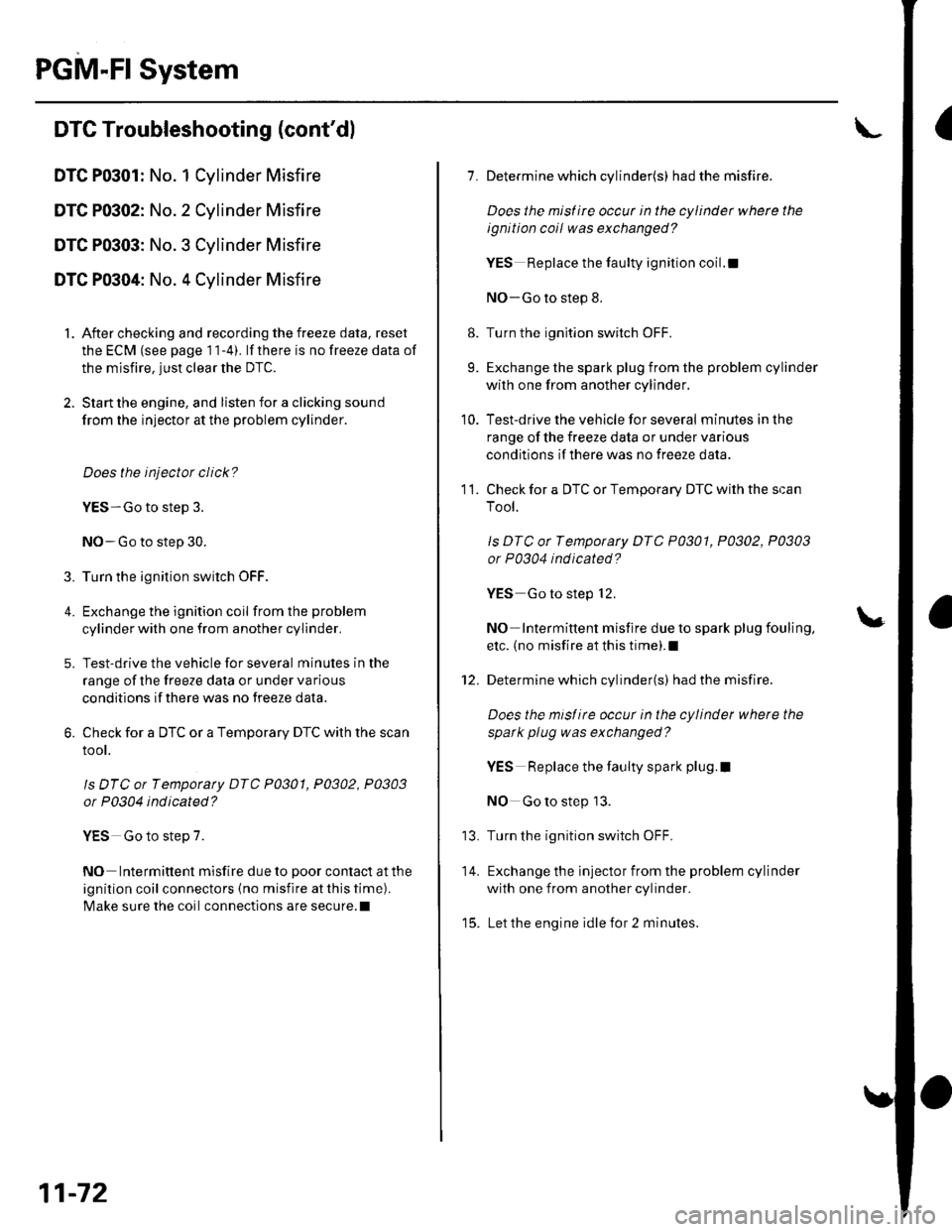
IDTC Troubleshooting (cont'dl
DTC P0301: No. 1 Cylinder Misfire
DTC P0302: No. 2 Cylinder Misfire
DTC P0303: No. 3 Cylinder Misfire
DTC P0304: No. 4 Cylinder Misfire
1. After checking and recording the freeze data, reset
the ECM (see page 1 1-4). lf there is no freeze data of
the misfire, just clear the DTC.
2. Start the engine, and listen for a clicking sound
from the injector at the problem cylinder.
Does the injector click?
YES-Go to step 3.
NO-Go to step 30.
3. Turn the ignition switch OFF.
4. Exchange the ignition coil from the problem
cylinder with one from another cylinder,
5. Test-drive the vehicle for several minutes in the
range of the freeze data or under va rious
conditions if there was no freeze data.
6. Check for a DTC or a Temporary DTC with the scan
root.
ls DTC or Tempotaty DTC P0301, P0302, P0303
or P0304 ind icated?
YES Go to step 7.
NO Intermittent misfire due to poor contact at the
ignition coil connectors {no misfire at this time).
Make sure the coil connections are secure.l
11-72
8.
9.
1.
11.
Determine which cylinder(s) had the misfire.
Does the misf ire occur in the cylinder where the
ignition coil was exchanged?
YES Replace the faulty ignition coil.!
NO-Go to step 8.
Turn the ignition switch OFF.
Exchange the spark plug from the problem cylinder
with one from another cylinder.
Test-drive the vehicle for several minutes in the
range of the freeze data or under various
conditions if there was no freeze data.
Check for a DTC or Temporary DTC with the scan
Tool.
ls DTC ot Tempotary DTC P0301, P0302, P0303
or P0304 ind icated?
YES Go to step 12.
NO Intermittent misfire due to spark plug fouling,
etc. (no misfire at this time).1
Determine which cylinder(s) had the misfire.
Does the misl ire occur in the cylinder where the
spark plug was exchanged?
YES Replace the faulty spark plug.l
NO Go to step 13.
Turn the ignition switch OFF.
Exchange the lnjector from the problem cylinder
with one from another cylinder.
Let the engine idle for 2 minutes.
10.
14.
t5.
Page 280 of 1139
16.Test-drive the vehicle for several minutes in the
range of the freeze data or under various
conditions if there was no freeze data.
Check for a DTC or a Temporary DTC with the scan
Tool.
ls DTC or Temporary DTC P0301, P0302, P0303
or P0304 indicated?
YES Go to step 18.
NO lntermittent misfire due to bad contact at the
injector connector (no misfire at this time). Make
sure the injector connection is secure. Check for
poor connections or loose terminals at the
injector.l
Determine which cylinder(s) had the misfire.
Does the misf ire occur in the cylinder where the
i njector w as exchanged ?
YES- Replace the faulty injector.I
NO-Go to step 19.
Turn the ignition switch OFF.
Disconnect the ignition coil 3P connector from the
problem cylinder.
Turn the ignition switch ON (ll).
't7 .
18.
19.
20.
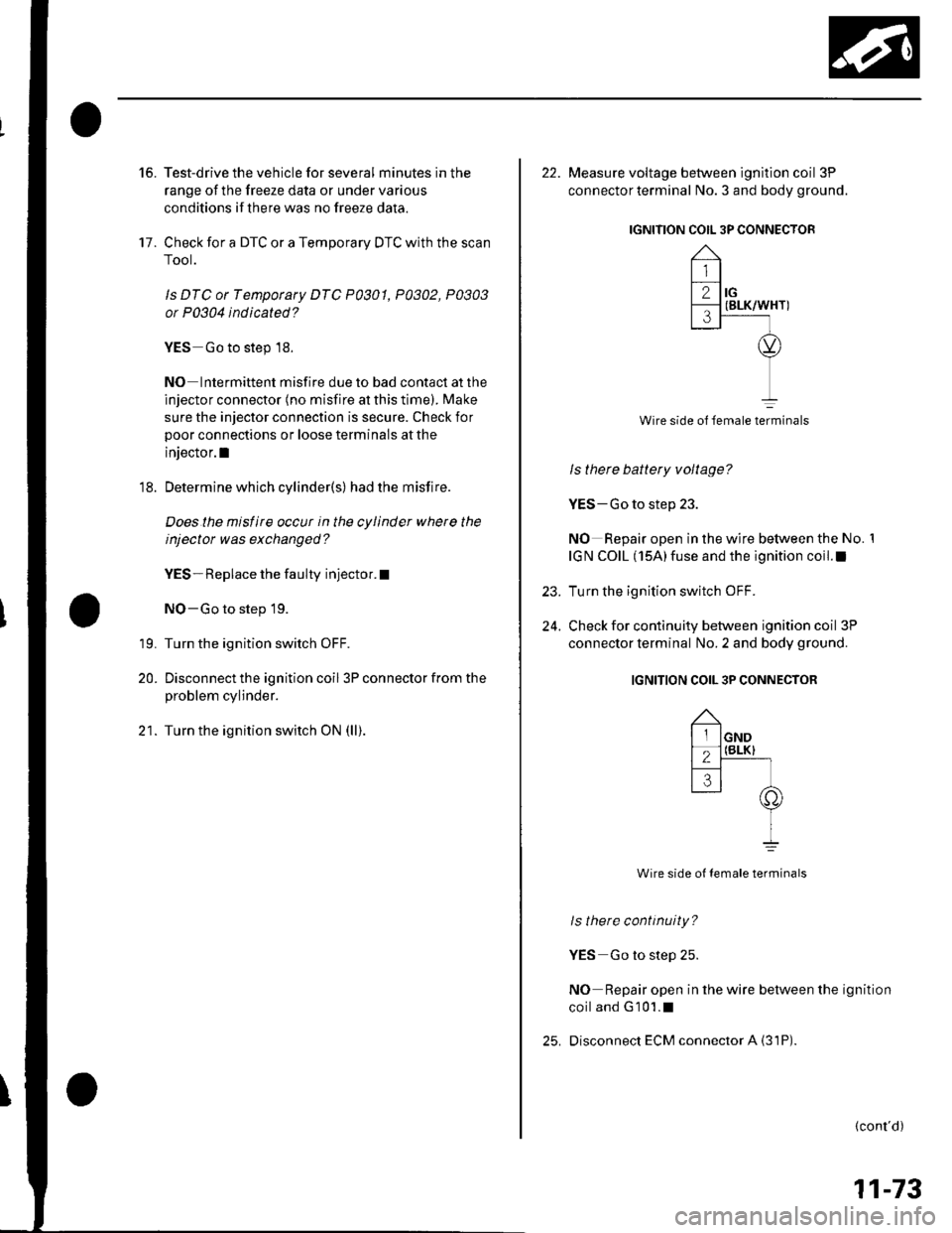
22. Measure voltage between ignition coil 3P
connector terminal No. 3 and body ground.
IGNITION COIL 3P CONNECTOR
Wire side ol female terminals
ls there battery voltage?
YES-Go to step 23.
NO Repair open in the wire between the No. 1
IGN COIL (15A)fuse and the ignition coil.I
Turn the ignition switch OFF.
Check for continuity between ignition coil 3P
connector terminal No. 2 and body ground.
IGNITION COIL 3P CONNECTOR
Wire side ot female terminals
ls there continuity?
YES Go to step 25.
NO Repair open in the wire between the ignition
coiland G101.1
Disconnect ECM connector A {31P)
23.
24.
(cont'd)
11-73