Ignition switch HONDA CIVIC 2003 7.G Workshop Manual
[x] Cancel search | Manufacturer: HONDA, Model Year: 2003, Model line: CIVIC, Model: HONDA CIVIC 2003 7.GPages: 1139, PDF Size: 28.19 MB
Page 1128 of 1139
)
Install the steering column covers.
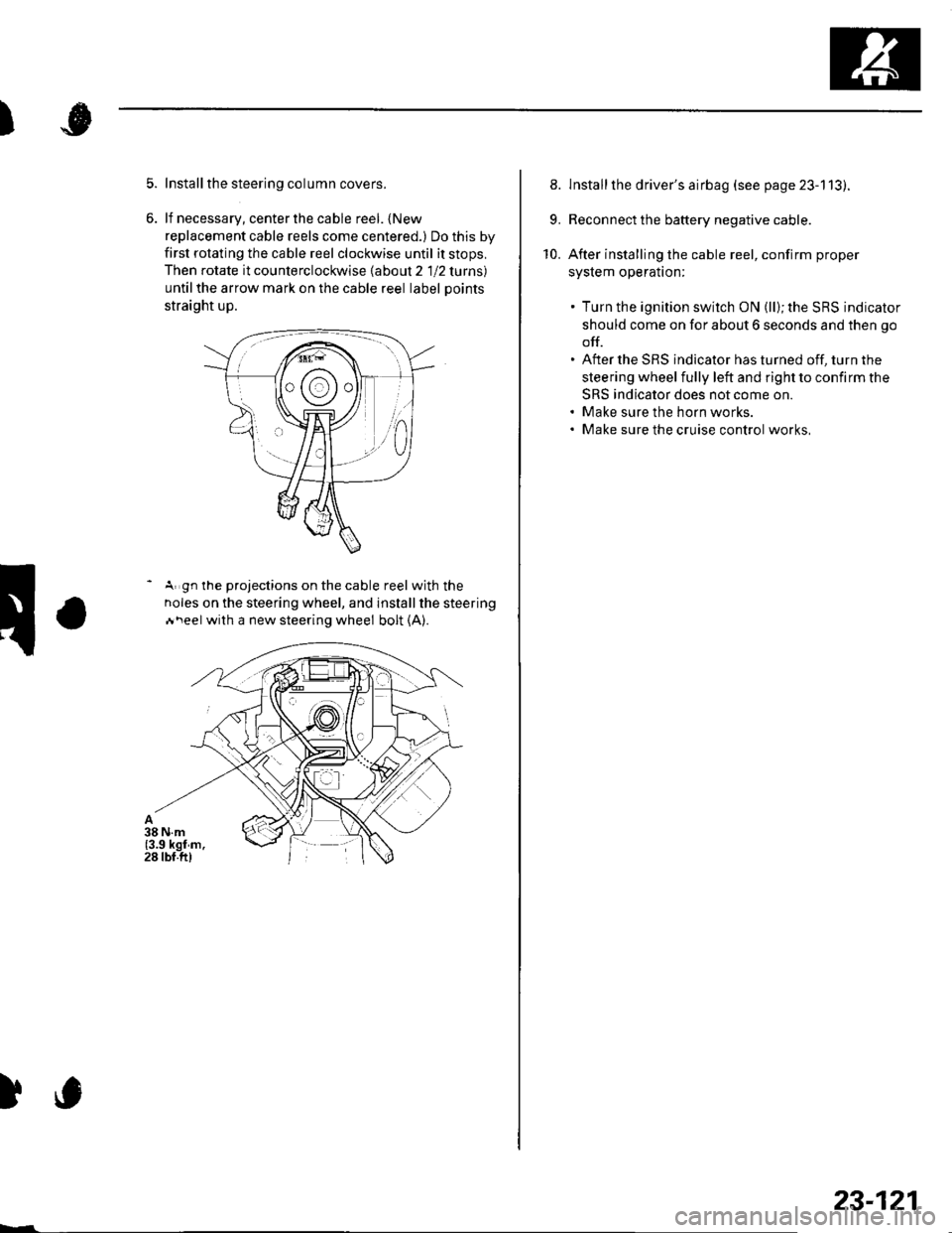
lf necessary, center the cable reel. {New
replacement cable reels come centered.) Do this by
first rotating the cable reel clockwise until it stops,
Then rotate it counterclockwise labout 2 1 12 lurns)
untilthe arrow mark on the cable reel label Doints
straight up.
- A gn the projections on the cable reel with the
noles on the steering wheel, and installthe steering
Ai\eel with a new steering wheel bolt (A).
)c
23-121
8. lnstallthe driver's airbag (see page 23-113).
9. Reconnect the battery negative cable.
10. After installing the cable reel, confirm proper
syslem operalton:
. Turn the ignition switch ON (ll); the SRS indicator
should come on for about 6 seconds and then go
off.. After the SRS indicator has turned off, turn the
steering wheel fully left and right to confirm the
SRS indicator does not come on.. Make sure the horn works.. Make sure the cruise control works,
Page 1129 of 1139
sRs
SRS Unit Replacement
Removal
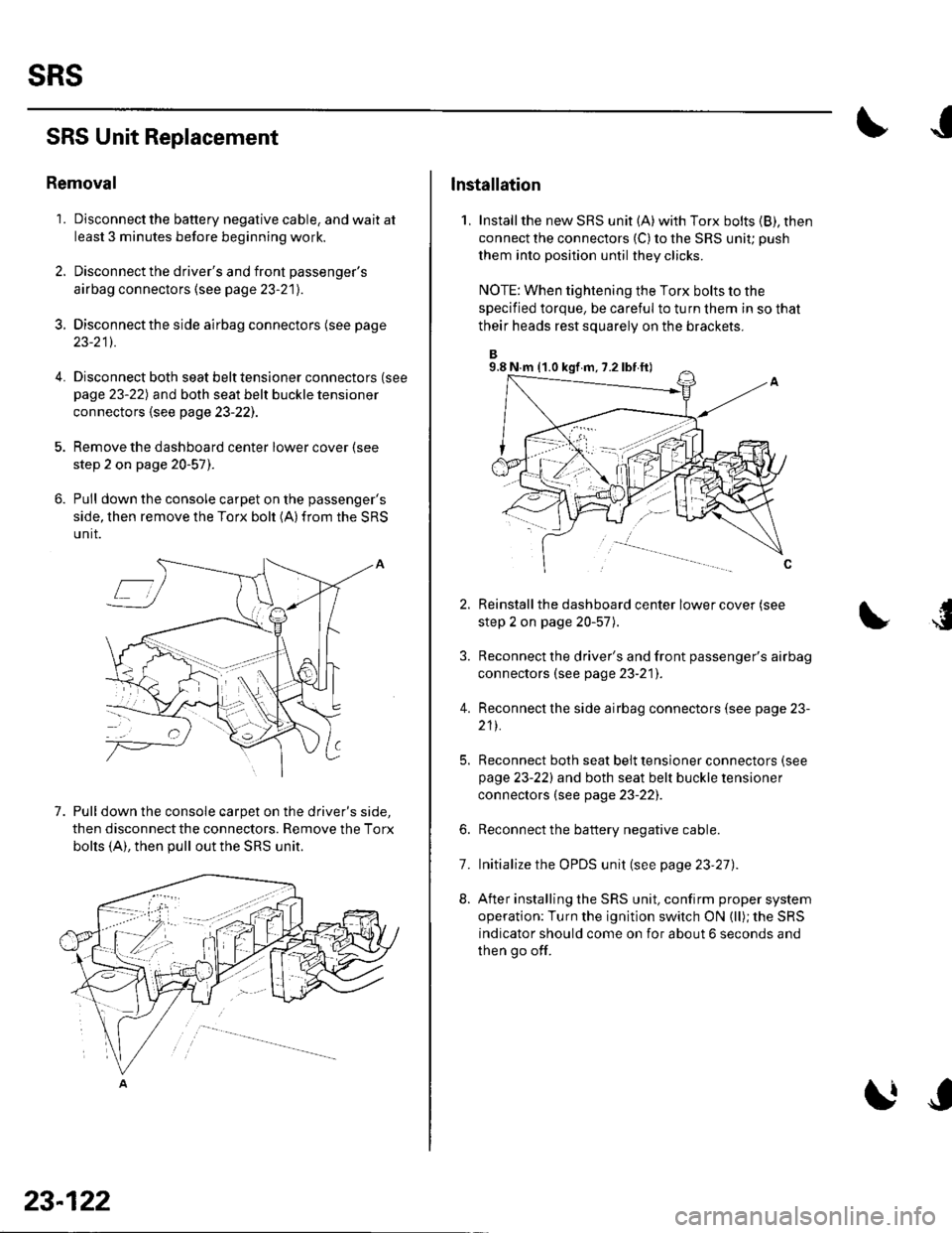
'1. Disconnect the battery negative cable, and wait at
least 3 minutes before beginning work.
2. Disconnect the driver's and front passenger's
airbag connectors (see page 23-21).
3. Disconnectthe side airbag connectors (see page
23-211.
4.Disconnect both seat belt tensioner connectors (see
page 23-22) and both seat belt buckle tensioner
connectors {see page 23-221.
Remove the dashboard center lower cover (see
step 2 on page 20-57).
Pull down the console carpet on the passenger's
side, then remove the Torx bolt (A)from the SRS
unit.
7. Pull down the console carpet on the driver's side,
then disconnect the connectors. Remove the Torx
bolts (A), then pull out the SRS unit.
23-122
lnstallation
1, Installthe new SRS unit (A)with Torx bolts (B), then
connect the connectors {C) to the SRS uniu push
them into position until they clicks.
NOTE: When tightening the Torx bolts to the
specified torque, be careful to turn them in so that
their heads rest squarely on the brackets.
Reinstall the dashboard center lower cover (see
step 2 on page 20-57).
Reconnect the driver's and front passenger's airbag
connectors (see page 23-21]'.
Reconnect the side airbag connectors (see page 23-
211.
Reconnect both seat belt tensioner connectors (see
page 23-221 and both seat belt buckle tensioner
connectors (see page 23-22).
Reconnect the battery negative cable.
Initialize the OPDS unit (see page 23'27).
After installing the SRS unit, confirm proper system
operation: Turn the ignition switch ON (ll); the SRS
indicator should come on for about 6 seconds and
then go off.
4.
6.
8.
7.
9.8 N.m (1.0 kgf m, 7.2 lbf ft)
Page 1130 of 1139
)
)
Side lmpact Sensor Replacement
Removal
1. Disconnect the battery negative cable, and wait at
least 3 minutes before beginning work.
2. Disconnect the appropriate side airbag 2P
connector (see step 4 on page 23-21).
3. Remove the seat assembly (see pa ge 20-71J.
4. Remove the front door silltrim and the B-pillar
lower trim panel (see page 20-50).
5. Disconnect the floor wire harness 2P connector
from the side impact sensor.
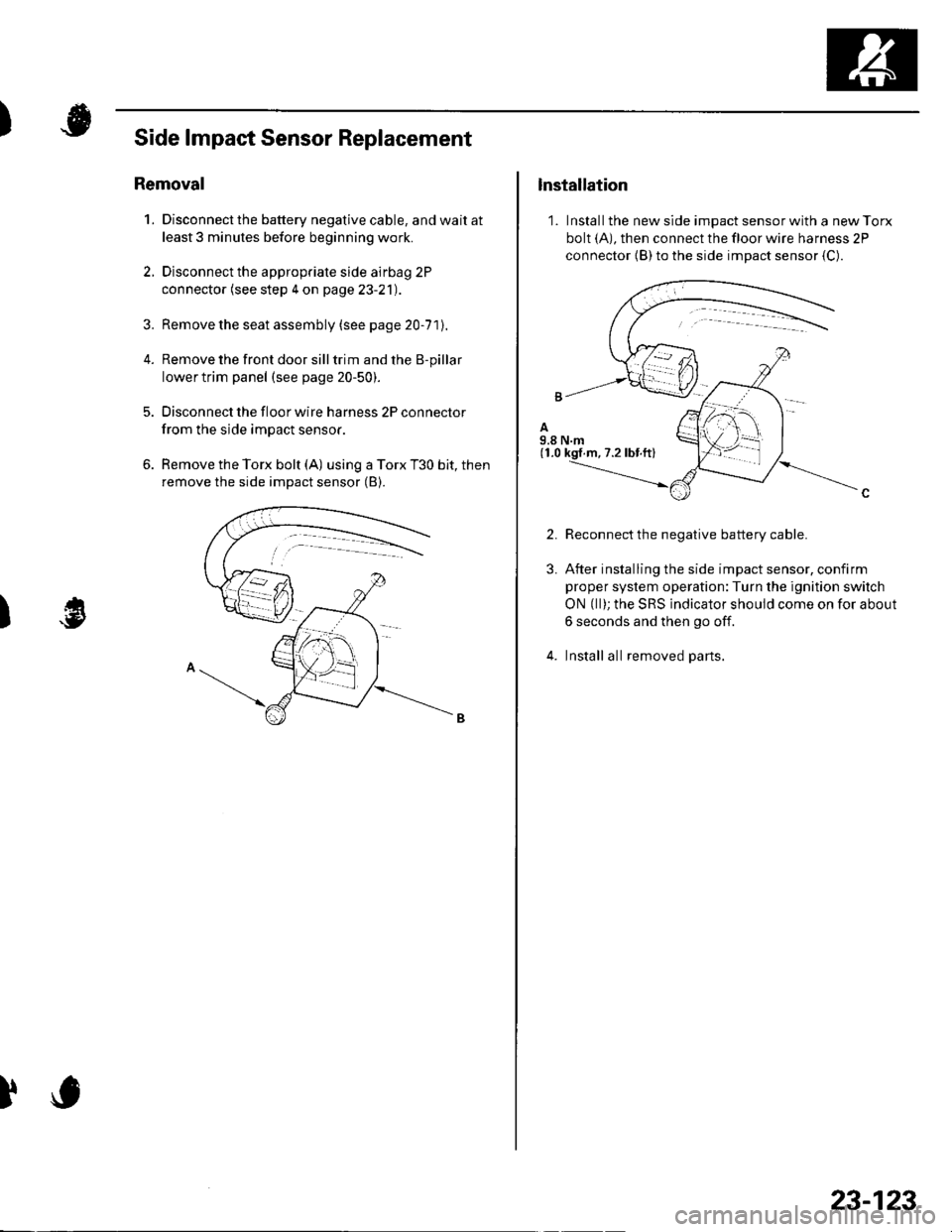
6. Remove the Torx bolt (A) using a Torx T30 bit, then
remove the side impact sensor (B).
)
lnstallation
1. Install the new side impact sensor with a new Torx
bolt (A), then connect the floor wire harness 2P
connector {B) to the side impact sensor {C).
2.
3.
Reconnect the negative battery cable.
After installing the side impact sensor, confirm
proper system operation:Turn the ignition switch
ON (ll); the SRS indicator should come on for about
6 seconds and then go off.
Install all removed parts.
23-123
Page 1131 of 1139
sRs
OPDS Unit Replacement
NOTE: Review the seat replacement procedures in the
body section before performing repairs or service.
Removal
1. Disconnect the battery negative cable. and wait at
least 3 minutes before beginning work.
2. Disconnect the passenger's side airbag harness 2P
connector (see step 4 on page 23-2'll.
3. Remove the front passenger's seat assembly (see
page 20-71)and seat-back cover (see page2O-15],.
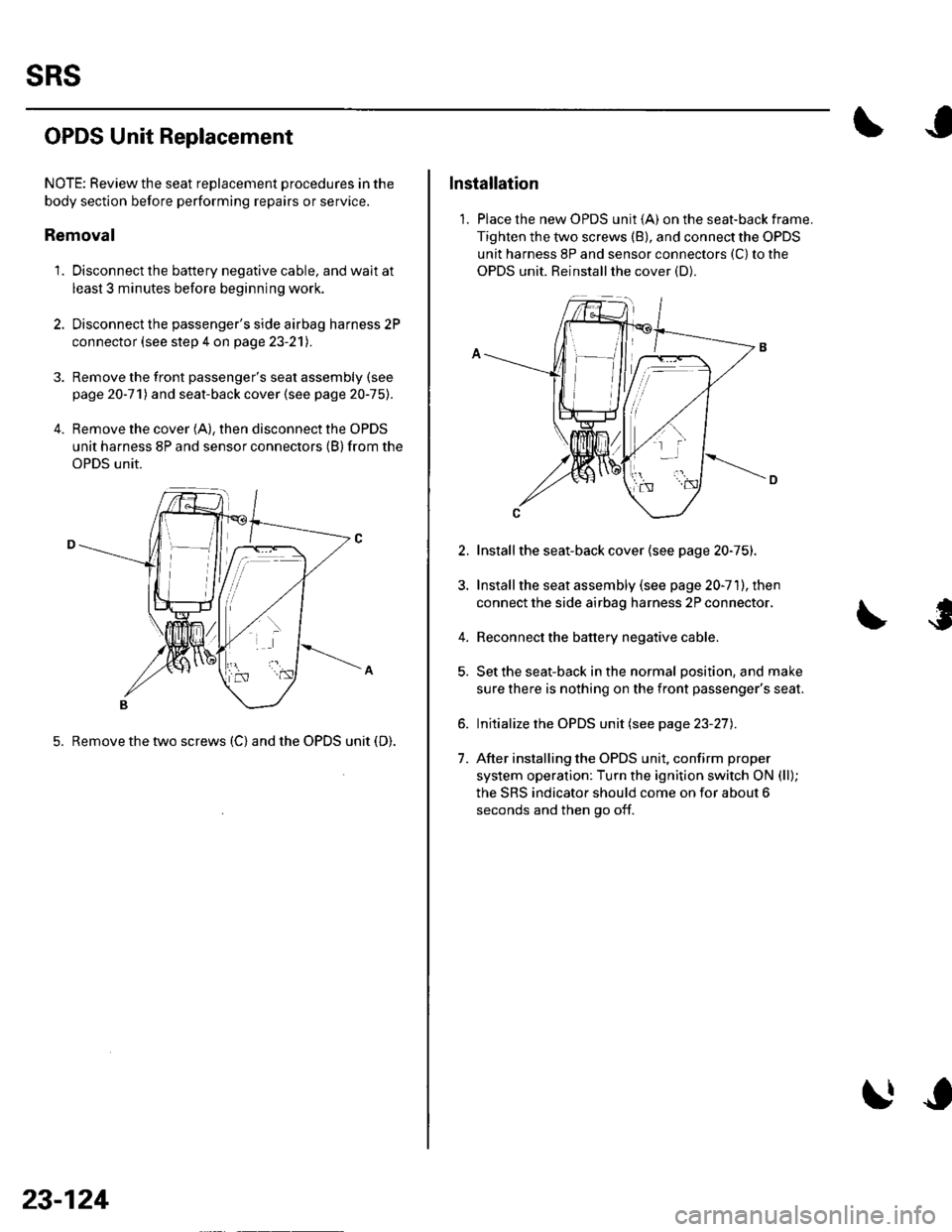
4. Remove the cover (A), then disconnect the OPDS
unit harness 8P and sensor connectors (B) from the
OPDS unit.
5. Remove the two screws (C) and the OPDS unit (D).
23-124
Installation
1. Place the new OPDS unit (A) on the seat-back frame.
Tighten the two screws (B), and connect the OPDS
unit harness 8P and sensor connectors (C) to the
OPDS unit. Reinstallthe cover (D).
2.
4.
1.
Installthe seat-back cover (see page 20-75).
Install the seat assembly (see page 20-71), then
connect the side airbag harness 2P connector,
Reconnect the battery negative cable.
Set the seat-back in the normal position, and make
sure there is nothing on the front passenger's seat.
Initialize the OPDS unit (see page 23-27).
After installing the OPDS unit, confirm proper
system operation: Turn the ignition switch ON (ll);
the SRS indicator should come on for about 6
seconds and then go off.
Page 1132 of 1139
)
1.
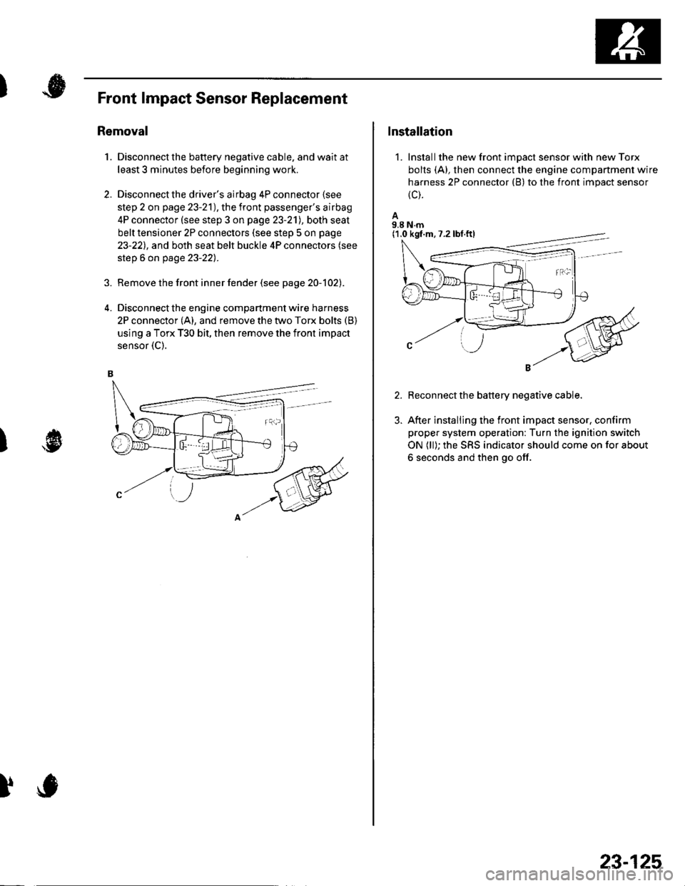
Front lmpact Sensor Replacement
Removal
Disconnect the battery negative cable. and wait at
least 3 minutes before beginning work.
Disconnect the driver's airbag 4P connector lsee
step 2 on page 23-21), the front passenger's airbag
4P connector (see step 3 on page 23-21), both seat
belt tensioner 2P connectors (see step 5 on page
23-221, and both seat belt buckle 4P connectors (see
step 6 on page 23-22).
Remove the front inner fender (see pag e 2O-1O21.
Disconnect the engine compartment wire harness
2P connector (A), and remove the two Torx bolts (B)
using a Torx T30 bit, then remove the front impact
sensor {C).
2.
)
)
Installation
1. Installthe new front impact sensor with new Torx
bolts (A), then connect the engine compartment wire
harness 2P connector (B) to the front impact sensor
{c).
A9.8 N.m
Reconnect the battery negative cable.
After installing the front impact sensor, confirm
proper system operation: Turn the ignition switch
ON (ll); the SRS indicator should come on for about
6 seconds and then go off.
(1.0 kgf.m,7.2lbf.ftl
23-125