Timing HONDA CIVIC 2003 7.G Owner's Manual
[x] Cancel search | Manufacturer: HONDA, Model Year: 2003, Model line: CIVIC, Model: HONDA CIVIC 2003 7.GPages: 1139, PDF Size: 28.19 MB
Page 236 of 1139

wEc/wc
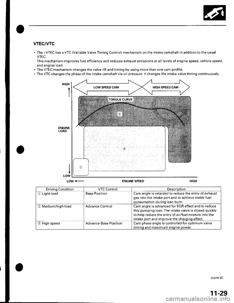
The i-WEC has a VTC (Variable Valve Timing Control) mechanism on the intake camshaft in addition to the usual
VTEC.
This mechanism improves fuel efficiency and reduces exhaust emissions at all Ievels of engine speed, vehicle speed.
and engine load.
The VTEC mechanism changes the valve lift and timing by using more than one cam profile.
The VTC changes the phase of the intake camshaft via oil pressure. lt changes the intake valve timing continuously.
HIGH
i
LOW <-ENGINE SPEED
Drivino ConditionVTC ControlDescriDtion
Qr Light-loadBase PositionCam angle is retarded to reduce the entry of exhaust
gas into the intake port and to achieve stable fuel
consumDtion durinq lean bu rn.
?l M ed iu m/h ig h-loadAdvance ControlCam angle is advanced for EGR effect and to reduce
this pumping loss. The intake valve is closed quickly
to help reduce the entry of airlfuel mixture into the
intake port and improve the charging effect.
€) High speedAdvance-Base PositionCam phase angle is controlled for optimum valve
timinq and maximum enoine oower.
{cont'd)
11-29
Page 237 of 1139

Fuel and Emissions Systems
(System Descriptions (cont'dl
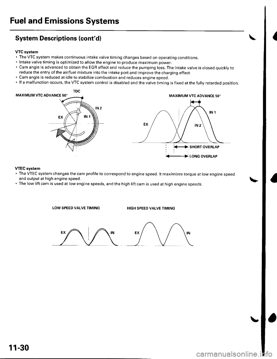
VTC system. The VTC system makes continuous intake valve timing changes based on operating conditions.. Intake valve timing is optimized to allow the engine to produce maximum power.'CamangleisadvancedtoobtaintheEGReffectandreducethepumpingloss.Theintakevalveisclosedquicklyto
reduce the entry of the airlfuel mixture into the intake port and improve the charging effect.. Cam angle is reduced at idle to stabilize combustion and reduces engine speed.'lfamalfunctionoccurs,theVTCsystemcontrol is disabled and the valve timing is fixed at the fully retarded position.
MAXIMUM VTC ADVANCE 50'
i l(-4 sHoRT oVERLAP
'+-|l LoNG oVERLAP
VTEC system' The VTEC system changes the cam profile to correspond to engine speed. lt maximizes torque at low engine speedand output at high engine speed.. The low lift cam is used at low engine speeds, and the high lift cam is used at high engine speeds.
LOW SPEED VALVE TIMINGHIGH SPEED VALVE TIMING
TDC
MAXIMUM VTC ADVANCE 50'
11-30
Page 345 of 1139

ldle Control System
ldle Speed lnspection
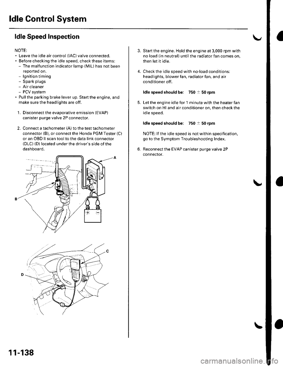
NOTE:' Leave the idle air control (lAC) valve connecled.. Before checking the idle speed, check these items:- The malfunction indicator lamp (MlL) has not been
reported on.- lgnition timing- Spark plugs- Air cleaner- PCV system. Pullthe parking brake lever up. Start the engine, and
make sure the headlights are off.
1. Disconnect the evaporative emission (EVAP)
canister purge valve 2P connector.
2. Connect a tachometer (A)to the test tachometer
connector (B), or connect the Honda PGM Tester (C)
or an OBD ll scan tool to the data link connector(DLC) (D) located under the driver's side of the
dashboard.
11-138
4.
3.
5.
6.
Start the engine. Hold the engine at 3,000 rpm with
no load (in neutral) until the radiator fan comes on,
then let it idle.
Check the idle speed with no-load conditions;
headlights, blower fan, radiator fan, and air
conditioner off.
ldle speed should be: 750 t 50 rpm
Let the engine idle for 1 minute with the heater fan
switch on Hl and air conditioner on, then check the
idle speed.
ldle speed should be: 750 t 50 rpm
NOTE: lf the idle speed is not wilhin specification,
go to the Symptom Troubleshooting Index,
Reconnect the EVAP canister purge valve 2P
connector.
Page 1139 of 1139

SuspensionAdjustment................-............................184 VComponent Location Index................. 20-17
Windshield GlessReplacement............-..............-............. 20 19
Synchro Ring, Triple-coneInspection...............-..........................1339 ValveGuides
Synchro SleeveInspectaon/Reassemb1y ....................... 13 39
Inspection ............-.-................................ 6 32Beplacement ..........-................................ 6 33 Wiper Intermittent Control Unit,Rear WindowInput Test
T
Valve SeatsRepair ...................................................... 6 35.....22-134
WiDer Motor, Rear WindowRep1acement....................................... 22-1 46Adjustment .-.-.......Removal ...-...-......................................-... 6-31 WiDer Motor, windshield6-9
.....6-32 Test.......-..........-.....-.............................22-143Taillight
ThermostaiTest ........................
Inspec!on
Vehicle Speed Signal Circuit
VTC System
Wiper/WasheI
Wi.ing System
10 4 Troubleshooting .....-... ..........................22-65 Component Location In dex ..............22-134Replacement.....-...-....... ...................... 10 IvssThrottle BodyTest ..................Removal/lnstallation .. . . . . . .. ... 11-'165 VTC ActuatorDisassembly/Feassemb|y................-11-166 Inspection
Circuit Diagram .......................... 22-136, 131
Replacement -.............. ............ .............22 61 Wiper/Washor SwitchTesVReplacement .............................. 22-1 40
.................68 WireHarnesses
11-160
Replacement ........................................... 6 24 (Seefirstpageofthislndex)Throttle CableAdjustment ...... ...-.................... 11163 VTC Oil ConlrolSolenoid ValveRemoval/1nsta11ation..........................11164 Removal....-...-... |1-127 HowtoIn{ormation ...............................223Belay and Control UnitLocations .-....-.............. -.-.-....- 22-7, 4, 1 1, 12Beplacement.........-............................... 1767 ComponentLocationlndex.............. 11-117Tie-rod Ball Joint Boots
lnstallation
Replacement
Turn Signal/Hazard Relay
tsTiming/Cam ChainVTEC Solenoid Valve...612 Femoval/lnspection....-......................11-128................ 6 15
Timing/Cam Chain Auto-tensionelRemoval/1nsta11ation..............................6-19 W
Troubleshooting{See first page ot this Index)
Turn Signal Light
Timing/Cam Chain CaseOil SealInstallation......................-......................6,21 Washer Fluid Level SwitchTesVReplacement .............................. 22 1 44Trailing ArmsRemoval/lnstallation .............. . . . . ..... 18 33 Washer Fluid ReservoirReplacement ....................................... 22-1 46tnmComponent Location lndex ................- 20 49 Washer Motor, WindshieldRemoval/lnstallation ..-.......20 50,51,52,53 Test -..............-.............. ........................22 144
Washer Tube, WindshieldReplacement......-...-............................ 22 1 47
W.ter Outlet.........22 A4 Installation ..................-........................... '10-9
InputTest........22-87 lnstallation................ 10IWeter Passage
Wheels andTires
Turn Signal/Hazard Warning Lights Water PumpComponent Location In dex .................22 85 Inspection ........................... .. . . . ....... 10 5Circu it Diagram ................-................... 22-86 Replacement .-......................................... 10 5
U
WheelBearingsInspec|ion ....................................... ....... 18 8
Wheel Speed SensorsInspection ..-..,.,.,,.,,,,,.,.,,,...................... 19-59Replac€ment ........-....... . . . . . . .. -.... 19-59UndeFdash Fuse/R€lay BoxRemoval/lnstaf lation ............................ 22-49
Upper ArmsRemoval/|nsta11ation................. ... 18-32
],sInspect|on