caliper HONDA CIVIC 2003 7.G Owner's Manual
[x] Cancel search | Manufacturer: HONDA, Model Year: 2003, Model line: CIVIC, Model: HONDA CIVIC 2003 7.GPages: 1139, PDF Size: 28.19 MB
Page 618 of 1139
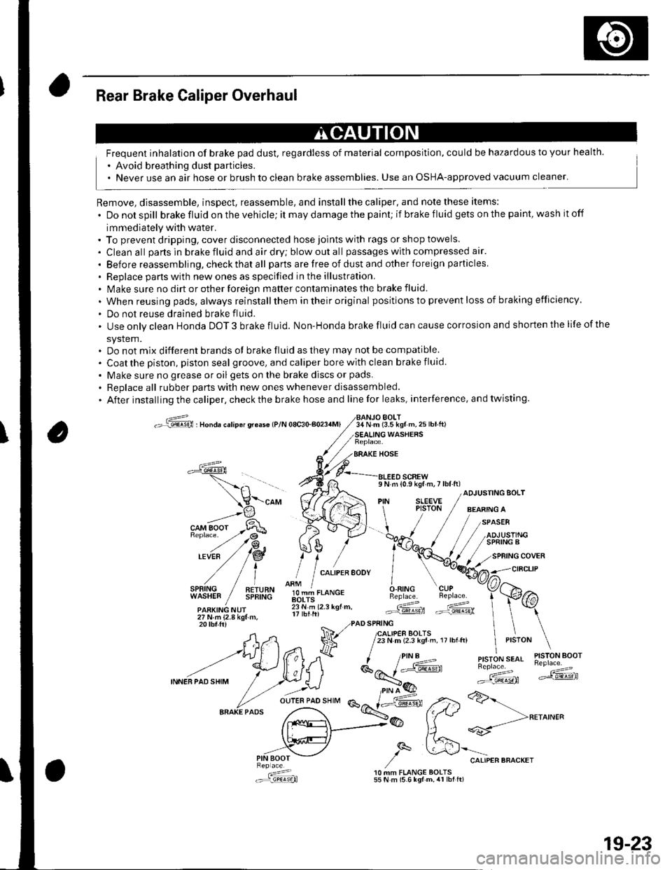
Rear Brake Caliper Overhaul
Frequent inhalation of brake pad dust, regardless of material composition, could be hazardous to your health.
' Avoid breathing dust particles.
. Never use an air hose or brush to clean brake assemblies. Use an OSHA-approved vacuum cleaner'
Remove, disassemble, inspect, reassemble, and installthe caliper, and note these items:
. Donotspill brake fluid on the vehicle; it may damage the paint; if brake f luid gets on the paint, wash it off
immediately with water.. To prevent dripping. cover disconnected hose joints with rags or shop towels.
. Cleanall partsinbrakefluidandairdry;blowoutall passageswith compressed air'
. Before reassembling, check that all parts are free of dust and other foreign particles
. Replace pans with new ones as specified in the illustration.. Make sure no dirt or other foreign matter contaminates the brake fluid.
. When reusing pads, always reinstallthem in their original positions to prevent loss of b ra king efficie ncy.
. Do not reuse drained brake fluid.
. Use only clean Honda DOT 3 brake fluid. Non-Honda brake fluid can cause corrosion and shorten the life of the
system.. Do not mix different brands ot brake fluid as they may not be compatible.
. Coatthe piston, piston seal groove, and caliper bore with clean brake fluid.
. Make sure no grease or oil gets on the brake discs or pads.
. Replaceall rubber parts with new ones whenever disassembled.
. After installing the caliper, check the brake hose and line for leaks, interference. and twisting.
oG , nonau."rip6r qreas€ lP/N 08c30-aoa4Ml34 N.m (3.5 kgf m,25lbtft)BOLT
WASHERS
BRAKE HOSE
a
l,i,,'IltE" / !!;,ff
olT-J,.o"c.O.RING CUPBeplace. Beplace.
.ARKING NUr lii.'i rz.r rgr.. Gd ffi27Nm{2.8kgtm,
\-"o, V((rA ",1 ;[.,.JF /;;;;---
t H\a \l / t,i*t'*"
?,,.t/*"^.,,.:,"", /"V4#
ADJUSTING BOLT
,/
27Nm{2.8kgf.m,20 tbf.ftr PAD SPRING
A,n Na 7lfl,lif,loffi ',,0,n, ,,:,o" \
--t)(*ff l^7k ''"'t!1'ry#'
INNEBPA'SHIM
/ .r.:._U i*E'( ":;*" *dF ,.2>a>-
fr.x{_>@ fftt **-->**^'"
,,.-"iV ,/q &'"o.,"."""o"^.,
: 10 MM FLANGE BOLTS.:r=,9!q!q}l 55 N m (5.6 lgf-m, 4r lbt ft)
19-23
Page 619 of 1139
Conventional Brake Components
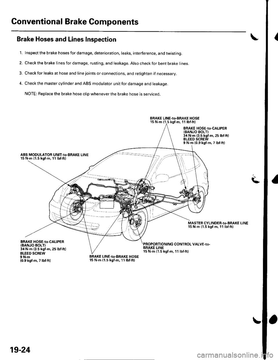
{Brake Hoses and Lines Inspection
1. Inspect the brake hosesfordamage, deterioration, leaks, interference, andtwisting.
2. Check the brake lines for damage, rusting. and leakage. Also check for bent brake lines.
3. Check for leaks at hose and line joints or connections, and retighten if necessary.
4. Check the master cylinder and ABS modulator unit for damage and leakage.
NOTE: Replace the brake hose clip whenever the brake hose is serviced.
15 N.m (1.5 kgf.m, 11 lbf.ftl
ABS MODULATOR UNIT-Io-BRAKE LINE15 N.m {1.5 kgf m.11 lbf.ftl
BRAKE HOSE-to-CALIPERlBANJO BOLTI3il N.m {3.5 kgf.m.25 lbt'ft)BLEEO SCREW9 N.m {0.9 kgf.m,7 lbf.ftl
MASTER CYLINDEB-to-BRAKE LINE15 N m {1.5 kgt.m, ll lbf.ft)
CONTROL VALVE-to-
L
BRAKE HOSE.tO-CALIPER{BANJO BOLTI34 N.m {3.5 kgf.m, 25 lbl.ft)BLEED SCBEW9 N.m10.9 kgf.m, 7 lbf ft)
BRAKE LINE15 N.m 11.5 kgf m, 11 lbf.ft)
BRAKE LINE-Io-BRAKE HOSE15 N.m (1.5 kgf.m,11lbf.ftl
BRAKE LINE-to-BRAKE HOSE
t''/,i'i'
,/ ,l
t t,.. -)
19-24
Page 620 of 1139
Brake Hose Replacement
NOTE:. Do not spill brake fluid on the vehicle; it may damage
the paint; if brake fluid gets on the paint, wash it off
immediately with water.. To prevent dripping, cover disconnected line joints
with rags or shop towels.. Before reassembling, check that all parts are free of
dust and other foreign particles.
. Replace parts with new ones whenever specified to
do so.
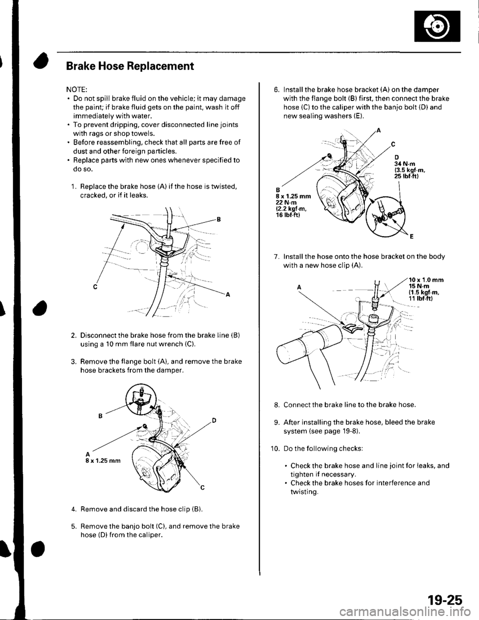
1 . Replace the brake hose (A) if the hose is twisted,
cracked, or if it leaks.
Disconnect the brake hose from the brake line (B)
using a 10 mm flare nut wrench {C)
Remove the flange bolt (A), and remove the brake
hose brackets from the damper.
Remove and discard the hose clip (B).
Remove the banjo bolt (C), and remove the brake
hose (D) {rom the caliper.
4.
I x 1.25 mm
6. Installthe brake hose bracket (A)on the damper
with the flange bolt (B) first, then connect the brake
hose (C) to the caliper with the banjo bolt {D) and
new sealing washers (E).
7. lnstallthe hose onto the hose bracket on the bodv
with a new hose clip (A).
10 x 1.0 mm15 N.mi (1.5 kgf.m,
! 1t tbt.ftl
Connect the brake line to the brake hose.
After installing the brake hose, bleed the brake
system (see page l9-8).
Do the following checks:
. Check the brake hose and line joint for leaks, and
tighten if necessary.. Check the brake hoses for interference and
twisting.
9.
10.
19-25
Page 634 of 1139
ABS Components
System Description (cont'd)
ABS Modulator
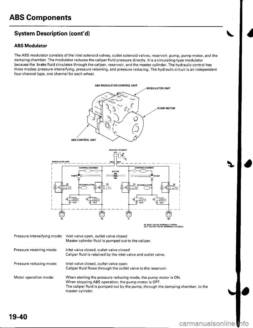
The ABS modulator consists of the inlet solenoid valves, outlet solenoid valves, reservoir, pump, pump motor, and the
damping chamber. The modulator reduces the caliper fluid pressure directly. lt is a circulating-type modulator
becausethe brakefluidcirculatesthroughthecaliper,reservoir,andthemastercylinder.Thehydrauliccontrol has
three modes: pressure intensifying, pressure retaining, and pressure reducing. The hydraulic circuit is an independent
four-channeltype, one channel for each wheel.
Pressure intensifying mode: Inletvalve open, outlel valve closed
Master cylinder fluid is pumped out to the caliper.
Pressure retaining mode: lnlet valve closed, outlet valve closed
Caliper fluid is retained by the inlet valve and outlet valve.
Pressure reducing mode: Inlet valve closed, outlet valve open
Caliper fluid flows through the outlet valve to the reservoir.
lvlotor operation mode: When starting the pressure reducing mode, the pump motor is ON.
When stopping ABS operation, the pump motor is OFF.
The caliper fluid is pumped out by the pump, through the damping chamber, to the
master cvlinder.
19-40
Page 635 of 1139
t
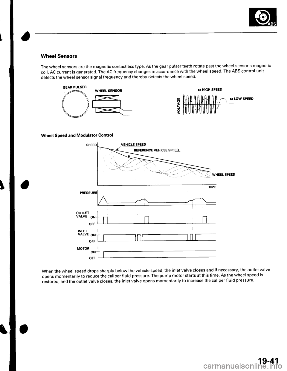
Wheel Sensors
The wheel sensors are the magnetic contactless type. As the gear pulser teeth rotate past the wheel sensor's magnetic
coil, AC current is generated. The AC frequency changes in accordance with the wheel speed. The ABS control unit
detects the wheel sensor signal frequency and thereby detects the wheel speed.
!t LOW SPEED
Wheel Speed and Modulator Control
8E!EEETqE VEJ!q!ESPEEq
5
PRESSURE
OUTLETVALVE 9p
OFF
INLETVALVE oN
OFF
MoroR I-,. ltlOFF
When the wheel speed drops sharply below the vehicle speed, the inlet valve closes and il necessary, the outlet valve
opens momentarily to reduce the caliper fluid pressure. The pump motor starts at this time. As the wheel speed is
restored, and the outlet valve closes, the inlet valve opens momentarily to increase the caliper fluid pressure.
GEAR PULSERWHEEL S€NSOR.r HIGX SPEED
19-41