ect HONDA CIVIC 2003 7.G Workshop Manual
[x] Cancel search | Manufacturer: HONDA, Model Year: 2003, Model line: CIVIC, Model: HONDA CIVIC 2003 7.GPages: 1139, PDF Size: 28.19 MB
Page 406 of 1139
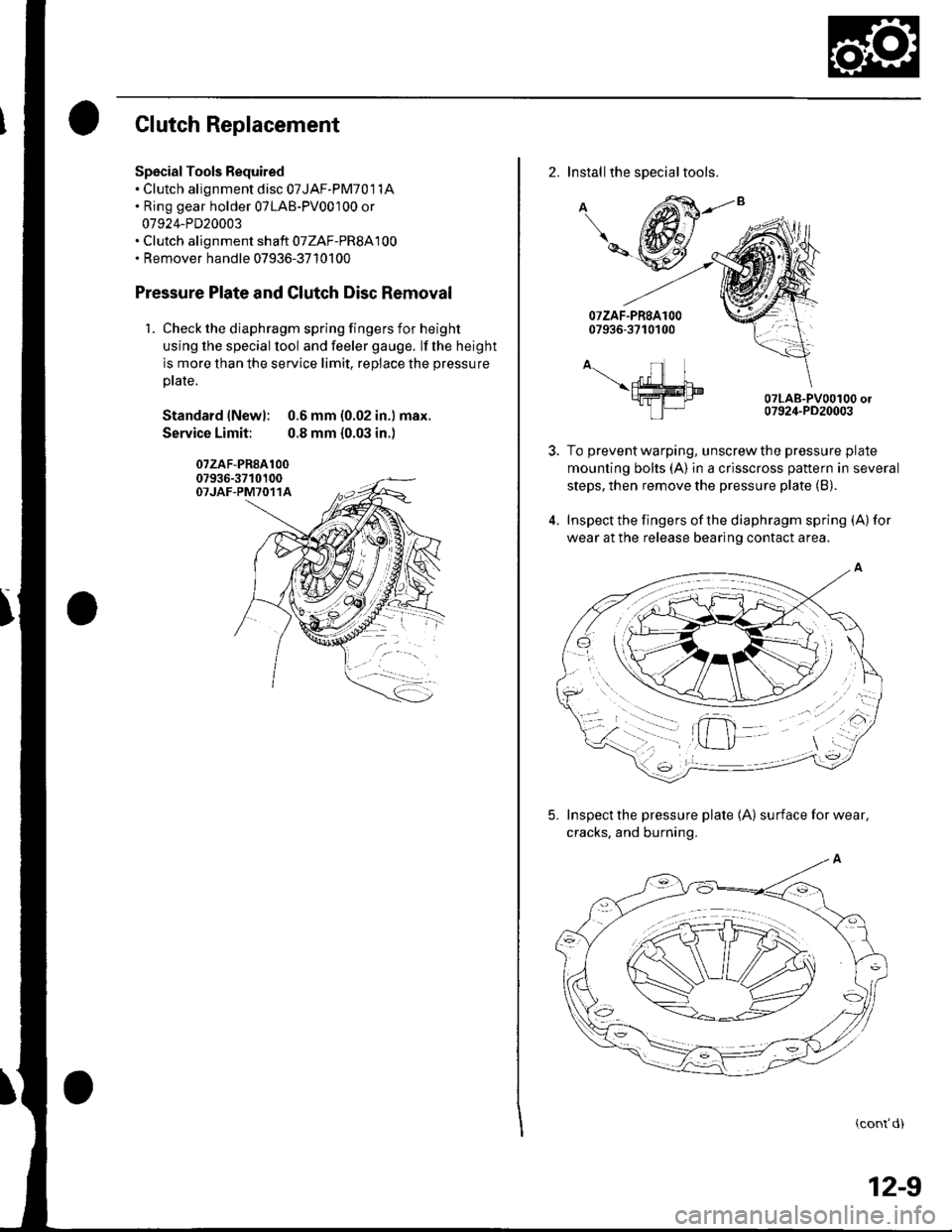
Clutch Replacement
Spscial Tools Required. Clutch alignment disc 07JAF-PM701 1A. Ring gear holder 07LAB-PV00100 or
07924-PD20003. Clutch alignment shaft 07ZAF-PR8A100. Remover handle 07936-3710100
Pressure Plate and Glutch Disc Removal
1. Check the diaphragm spring fingers for height
using lhe special lool and feeler gauge. lf the height
is more than the service limit, replace the pressure
ptate.
Standard lNewl: 0.6 mm (0.02 in.) max.
Service Limit: 0.8 mm {0.03 in.)
07zAF-PR8A10007936-3710100OTJAF-PM7O11A
2. Installthe special tools.
A
\-
A-.- nl I\ffim9fra-I tP|-
07LAB-PV00100 or07924-PD20003
To prevent warping, unscrew the pressure plate
mounting bolts (A) in a crisscross pattern in several
steps, then remove the pressure plate (B).
Inspect the fingers of the diaphragm spring (A) for
wear at the release bearing contact area.
5. Inspect the pressure plate 1A) surfaceforwear,
cracks. and burning.
(cont'd)
12-9
Page 407 of 1139
Clutch
Clutch Replacement (cont'd)
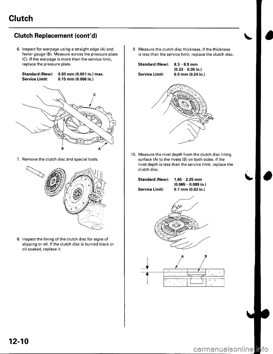
6. Inspecl for warpage using a straight edge (A) and
feeler gauge (B). l\4easure across the pressure plate
(C). lf the warpage is more than the service limit,
replace the pressure plate.
Standard {New): 0.03 mm (0.001 in.) max.
Service Limit: 0.15 mm (0.006 in.)
7. Remove the clutch disc and sDecialtools.
Inspectthe lining ofthe clutch disc for signs of
slipping or oil. lf the clutch disc is burned black or
oil soaked. reolace it.
1d
12-10
9. lvleasu re th e clutch d isc th ickness. lfthethickness
is less than the service limit, replace the clutch disc.
Standard lNew): 8.3 8.9 mm(0.33 0.35 in.)
Service Limit: 6.0 mm {0.24 in.)
Measure the rivet depth from the clutch disc lining
surface (A) to the rivets (B) on both sides. lf the
rivet depth is less than the service limit, replace the
clutch disc.
Standard (New): 1.65 2.25 mm(0.065 0.089 in.)
Service Limit: 0.7 mm (0.03 in.)
10.
L
Page 408 of 1139
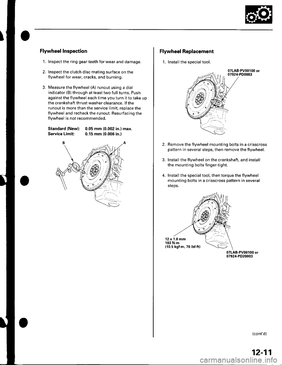
Flywheel Inspection
1. Inspect the ring gear teeth for wear and damage.
2. Inspect the clutch disc mating surface on the
flywheel for wear, cracks, and burning.
3. Measure the flywheel (A) runout using a dial
indicator (B) through at least two full turns. Push
against the flywheel each time you turn it to take up
the cra nksh aft th rust washer clea rance. lf the
runout is more than the service limit, replace the
flywheel and recheck the runout. Resurfacing the
flywheel is not recommended.
Standard (New): 0.05 mm (0.002 in.) max.
Service Limit: 0.15 mm (0.006 in.)
Flywheel Replacement
1. Installthe special tool.
2.
3.
4.
Remove the flywheel mounting bolts in a crisscross
pattern in several steps, then remove the tlywheel.
Installthe flywheel on the crankshaft, and install
the mounting bolts fingertight.
Installthe specialtool, then torque the flywheel
mounting bolts in a crisscross pattern in several
sreps.
12 x 1.0 mm103 N.m(10,s kst.m. 76 lbf ftl
(cont'd)
12-11
Page 411 of 1139
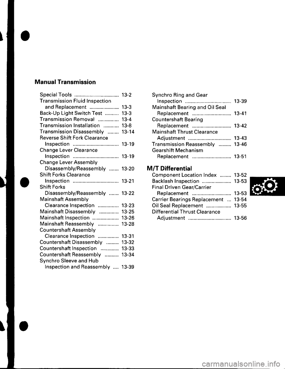
Manual Transmission
SpecialTools
Transmission Fluid Inspection
and Reo1acement ...................-.
Back-Up Light Switch Test ..........
Transmission Removal
Transmission Installation ...........
Transmission Disassemblv ........
Reverse Shift Fork Clearance
lnsoection
Change Lever Clearance
lnsoection
Change Lever Assembly
Disassembly/Reassembly .......
Shift Forks Clearance
Inspection
Shift Forks
Disassembly/Reassembly .......
Mainshaft Assemblv
Clearance Inspection
Mainshaft Disassembly
Mainshaft lnsoection
Mainshaft Reassembly
Countershaft Assemblv
Clearance Inspection
Countershaft Disassembly .........
Countershaft Inspection .............
Countershaft Reassembly ..........
Synchro Sleeve and Hub
Inspection and Reassembly ....
Synchro Ring and Gear
Insoection ....... 13-39
Mainshaft Bearing and Oil Seal
Replacement ........................,... 13-41
Cou ntershaft Bearing
ReDlacement .. 13-42
Mainshaft Thrust Clearance
Adiustment ..... 13-43
Transmission Reassemblv ......... 13-46
Gearshift Mechanism
Replacement ............................ 13-51
M/T Differential
Comoonent Location Index ........ 13-52
Backlash Inspection ..................... 13-53
Final Driven Gear/Carrier
Replacement .. 13-53
Carrier Bearings Replacement ... 13-54
Oil Seal Replacement .................. 13-55
Differential Thrust Clearance
Adiustment ..... 13-56
13-2
| 5-J
tJ-5
13-4
I J-at
13-14
13- 19
13- 19
13-20
13-21
13-22
13-23't3-25
13-26
| 5-2.5
13-31
13-32
13-33
13-34
13-39
Page 412 of 1139
Manual Transmission
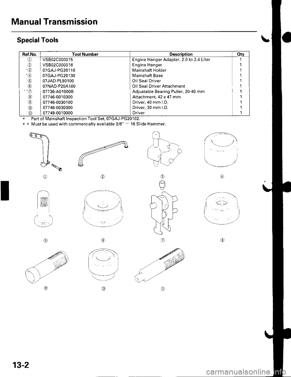
SpecialTools
Inspection Tool Set,
Must be used with commercially available 3/8" '16 Slide Hammer.
-4
Z-'
U
@o
I
rS'D
AD;nrf
\".,i'i
IN
@
I
@
@
-4
-a ,/
Q)-''
o
Ref.No.Tool NumberDescription Oty
(!lar\
ral
@
o
ori)
@
@
@
vs802c000015
vs802c000018
07GAJ-PG20'�]10
07GAJ-PG20130
07JAD-P190100
07NAD-P20A100
07736-A01000B
07746-0010300
07746-0030100
07746-0030300
07749-0010000
l,l
l
Engine Hanger Adapter, 2.0 to 2.4 Liter
Engine Hanger
Mainshaft Holder
Mainshaft Base
Oil Seal Driver
Oil Seal Driver Aftachment
Adjustable Bearing Puller, 20-40 mm
Attachment, 42 x 47 mm
Driver, 40 mm LD.
Driver, 30 mm LD.
Driver
on Tool Set. 07GAJ-PG20102.of Mainshaft
\'---''
13-2
Page 413 of 1139
Transmission Fluid Inspection and
Replacement
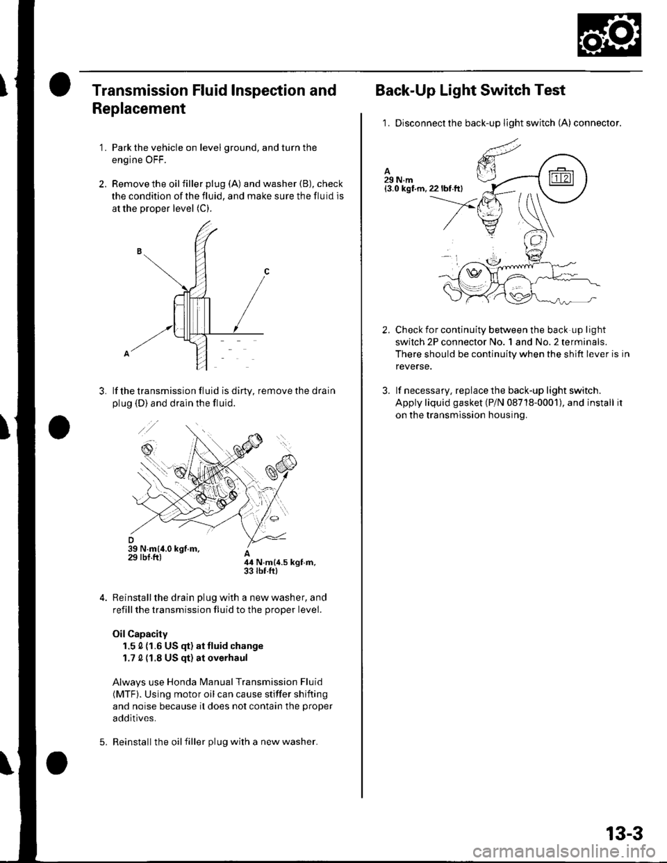
'1. Park the vehicle on level ground, and turn the
engine OFF.
2. Remove the oilfiller plug (A) and washer (B), check
the condition of the fluid, and make sure the fluid is
at the proper level (C).
lf the transmission fluid is diny, remove the drain
plug (D) and drain the fluid.
A44 N.m{4.5 kgt.m,33 rbr.ftl
Reinstall the drain plug with a new washer, and
refill the transmission fluid to the proper level.
Oil Capacity
1.5 0 (1.6 US (F) at tluid change
1.7 0 {1.8 US qt) at overhaul
Always use Honda Manual Transmission Fluid
(MTF). Using motor oil can cause stiffer shifting
and noise because it does not contain the proper
additives.
Reinstall the oil filler plug with a new washer.5.
13-3
Back-Up Light Switch Test
1. Disconnectthe back-up light switch (A) connector.
Check for continuity between the back up light
swilch 2P connector No. 1 and No.2 terminals.
There should be continuity when the shift lever is in
reverse.
lf necessary, replace the back-up light switch.
Apply liquid gasket (P/N 08718-0001), and install it
on the transmission housing.
2.
3.
Page 414 of 1139
Manual Transmission
Transmission Removal
SpecialTools Required. Engine hanger adapter.2.0 to 2.4 liter VSB02C000015. Engine hanger VSB02C000018. Engine support hanger, A & Reds AAR'T 12566'. Subframe adaDter EOS02C000011 '
* Available through the Honda Tool and Equipment
Program 888-424-6857
NOTE: Use fender covers to avoid damaging painted
surfaces.
4.
1.
7.
Write down the frequencies for the radio's preset
buttons. Disconnect the negative ( ) cable first,
then the positive ( )cable from the battery.
Remove the battery.
Remove the intake manifold cover {see page g-3).
Remove the air cleaner housing (see page 1 1-162).
Remove the intake air duct {see step 8 on page 5-3).
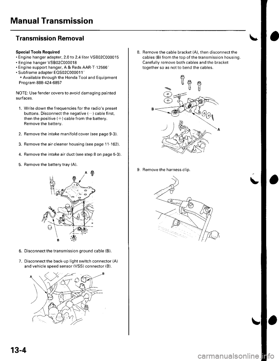
Remove the battery tray (A).
Disconnect the transmission ground cable (B).
Disconnect the back-up light switch connector (A)
and vehicle speed sensor (VSS) connector (B).
13-4
8. Remove the cable bracket (A). then disconnect the
cables (B) from the top of the transmission housing.
Carefully remove both cables and the bracket
together so as not to bend the cables.
9. Remove the harness clip.
I
HA @
ilB
Page 422 of 1139
Manual Transmission
Transmission Installation (cont'dl
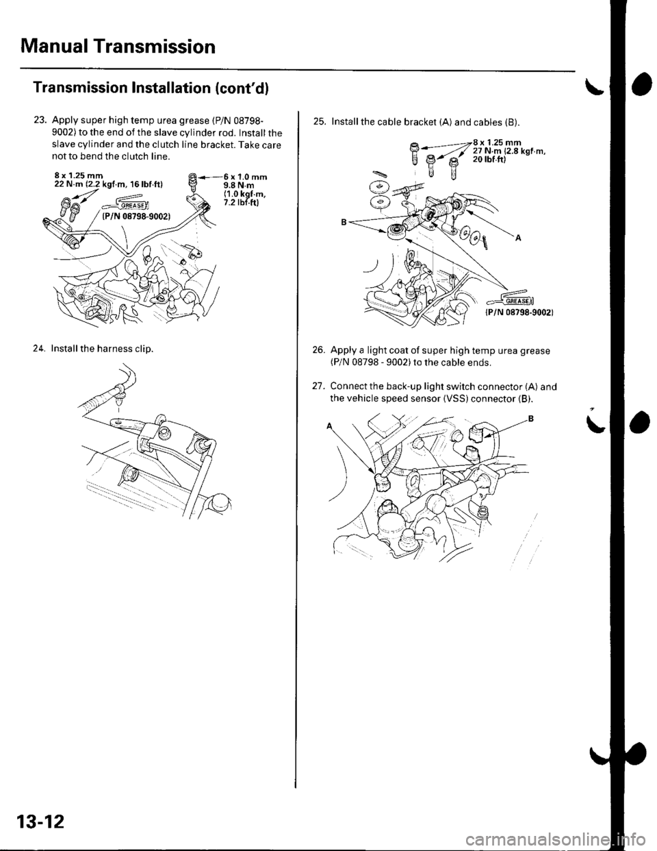
Apply super high temp urea grease (P/N 08798-
9002) to the end of the slave cylinder rod. Install the
slave cylinder and the clutch line bracket. Take care
not to bend the clutch line.
8 x 1.25 mm22 N.m (2.2 kgf.m, 16 lbf ft)6x1.0mm9.8 N.m(1.0 kgf.m,7.2 tbt.ftla^_#._gEEa9En(P/N 08798-9002)
24. Installthe harness clip.
13-12
25. Installthe cable bracket (A) and cables (B).
BWZ[i:i'u'T!'*n'-'
lPlN 08798-9002)
Apply a light coat of super high temp urea grease(P/N 08798 - 9002)to the cable ends.
Connect the back-up light switch connector (A) and
the vehicle speed sensor {VSS)connector (B).
26.
t1
Page 423 of 1139
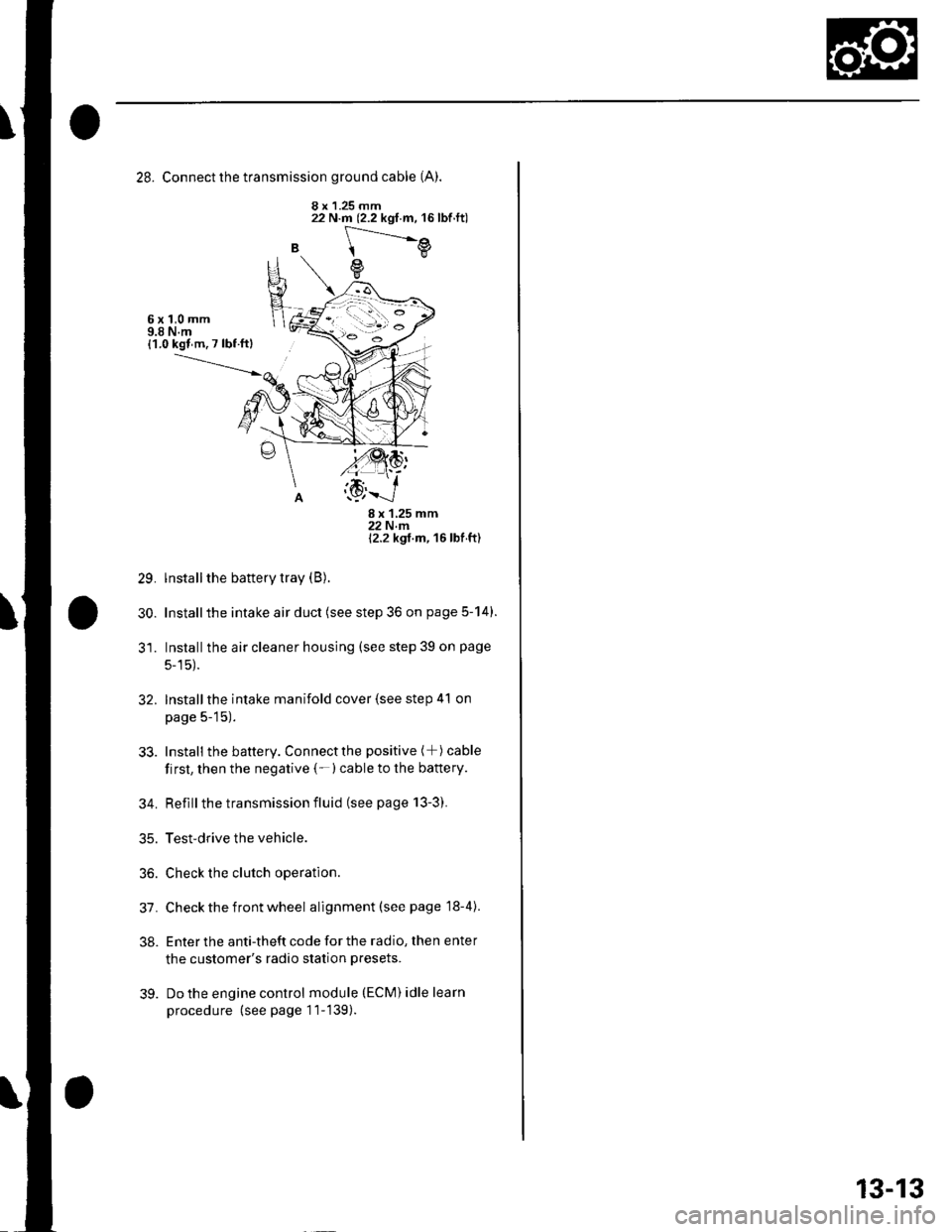
28. Connect the transmission ground cable (A).
8 x 1.25 mm
B
22 N.m (2.2 kgf.m, 16lbf.ft)
[---.-.---e
e
6x1,0mm9.8 N.m{1.0 kgl m. 7 lbf ftl
29.
30.
8x125mm22Nm12.2 kgt m, 16 lbf ft)
lnstall the battery tray (B).
Installthe intake air duct (see step 36 on page 5-14).
Installthe air cleaner housing (see step 39 on page
5-15).
Installthe intake manifold cover (see step 41 on
page 5-15).
Install the battery. Connectthe positive (+) cable
first, then the negative (-)cable to the battery.
Reflllthe transmission fluid (see page 13-3).
Test-drive the vehicle.
Check the clutch operation.
Check the front wheel alignment (see page 18-4).
Enter the anti-theft code for the radio, then enter
the customer's radio station presets.
Do the engine control module (ECM) idle learn
procedure (see page 11-139).
32.
33.
34.
35.
36.
31.
38.
39.
13-13
Page 428 of 1139
Manual Transmission
Transmission Disassembly (cont'd)
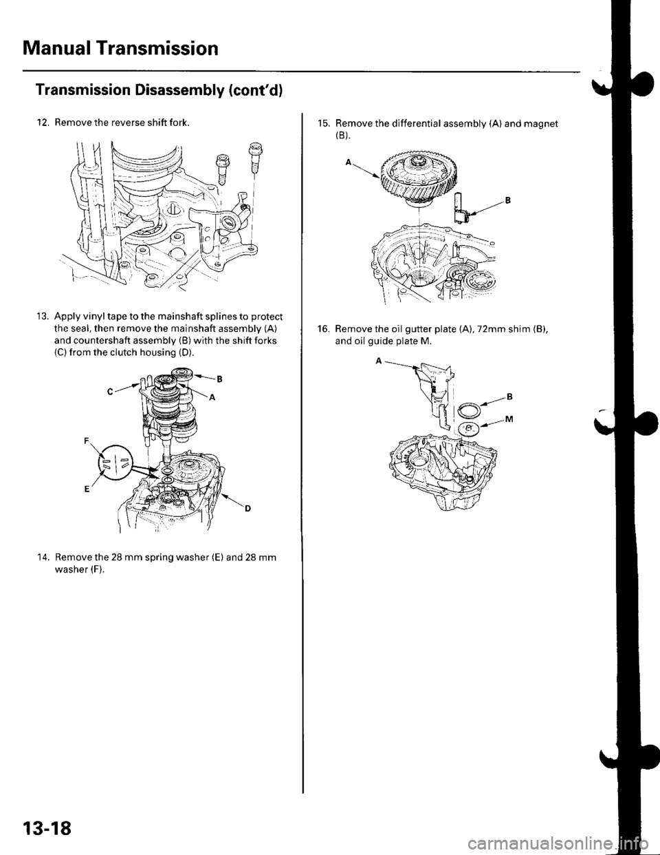
12. Remove the reverse shift fork.
Apply vinyl tape to the mainshaft splines to protect
the seal, then remove the mainshaft assembly (A)
and countershaft assembly (B) with the shift forks
{C)from the clutch housing (D).
14. Remove the 28 mm spring washer (E) and28mm
washer (F).
t7t1I
13-18
15. Remove the differential assembly (A) and magnet(B ).
Remove the oil gutter plate (A), 72mm shim (B),
and oil guide plate M.
16.