ect HONDA CIVIC 2003 7.G Workshop Manual
[x] Cancel search | Manufacturer: HONDA, Model Year: 2003, Model line: CIVIC, Model: HONDA CIVIC 2003 7.GPages: 1139, PDF Size: 28.19 MB
Page 457 of 1139
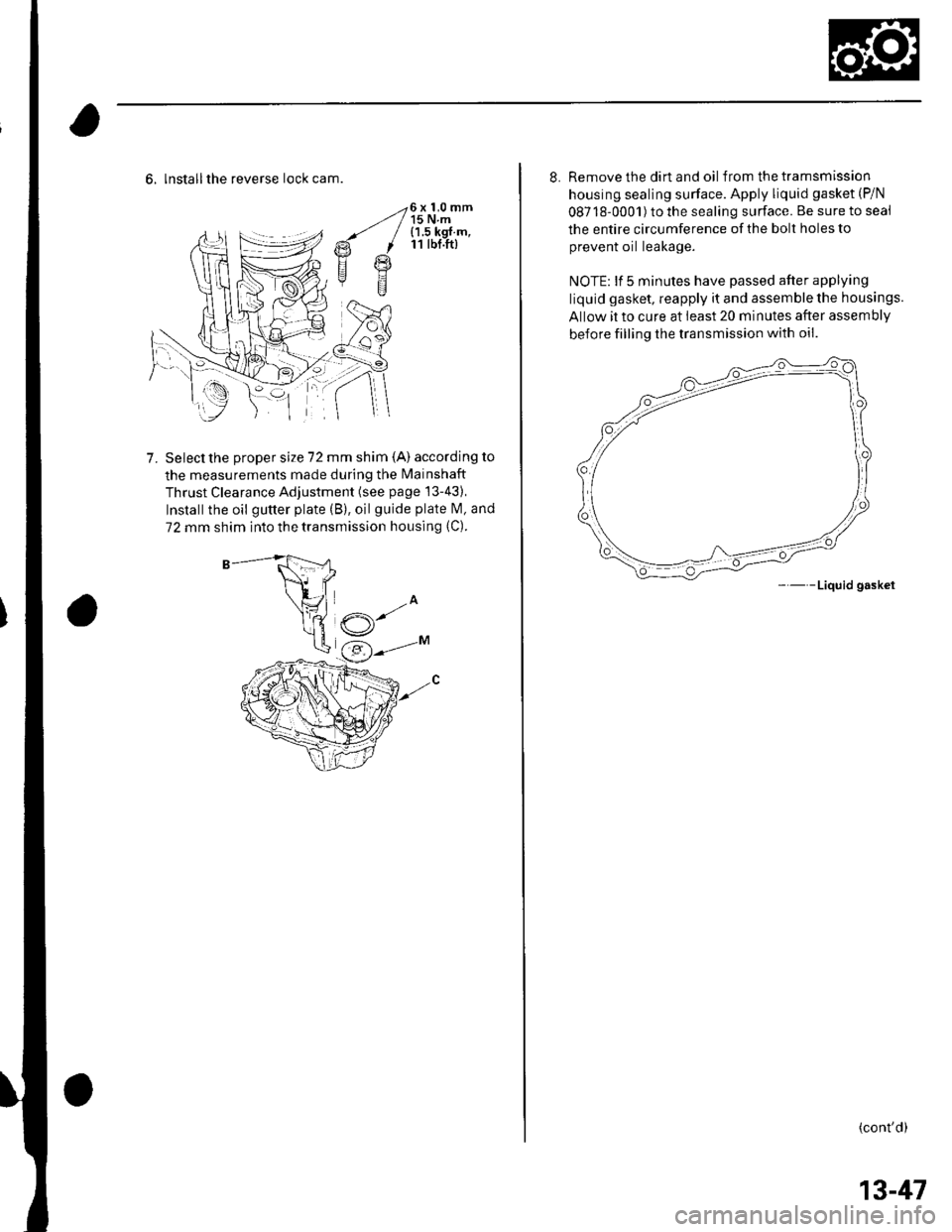
-26 x 1,0 mmz/ / 15 N.m--' / {1 5 kgf m,€t I 11 tbf.ft)
Fl g
E
6, lnstallthe reverse lock cam.
Select the proper size 72 mm shim (A) according to
the measurements made during the Mainshaft
Thrust Clearance Adjustment (see page '13-43),
Installthe oil gutter plate (B), oilguide plate l\4, and
72 mm shim into the transmission housing (C).
7.
8. Remove the dirt and oil f rom the tramsmission
housing sealing surface. Apply liquid gasket (P/N
08718-0001) to the sealing surface. Be sure to seai
the entire circumference of the bolt holes to
prevent oil leakage.
NOTE: lf 5 minutes have passed after applying
liquid gasket, reapply it and assemble the housings.
Allow it to cure at least 20 minutes after assembly
before filling the transmission with oil.
- - -Liquid gasket
{cont'd)
13-47
Page 462 of 1139
M/T Differential
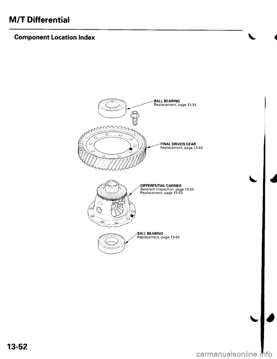
Component Location Index
DRIVEN GEARBeplacement, page 13-53
Backlash Insoection. oaoe 13-53Feplacemeni, paoe I 3-5-3
\
\
,<-=- ,/BALL BEARING
/ ,/ Beplacemenl, page 13-54
I \c1 l/
=/
13-52
(
I
Page 463 of 1139
\
Backlash lnspection
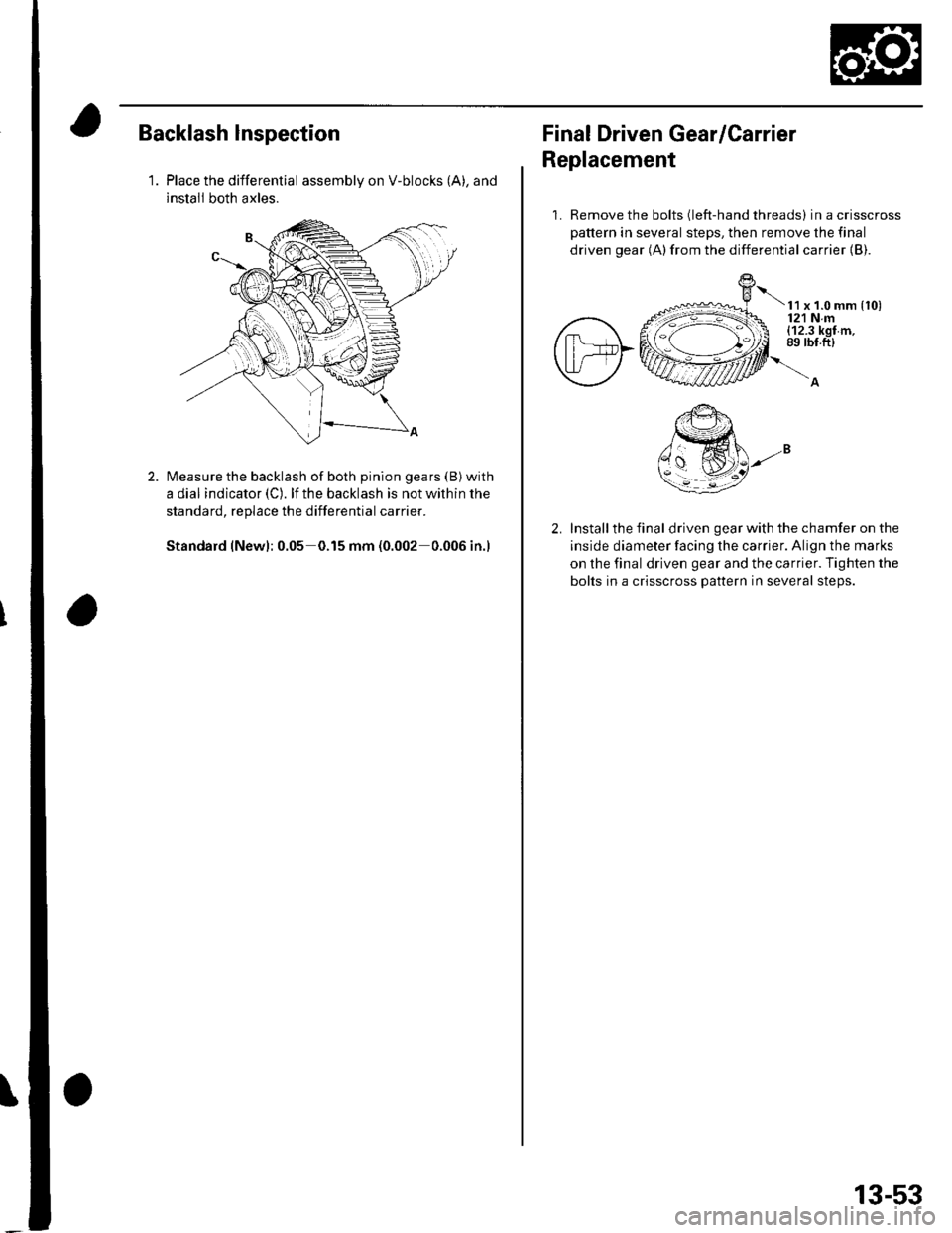
1.Place the differential assembly on V-blocks (A), and
install both axles.
Measure the backlash of both pinion gears (B) with
a dial indicator (C). lf the backlash is not within the
standard, replace the differential carrier.
Standard (New): 0.05 0.15 mm (0.002 0.006 in.)
Final Driven Gear/Carrier
Replacement
1. Remove the bolts (left-hand threads) in a crisscross
pattern in several steps, then remove the final
driven gear (A)from the differential carrier {B).
t x t.o mm {to)121 Nm(12.3 kgf m,89 rbt.ft)
Install the final driven gear with the chamfer on the
inside diameter facing the carrier. Align the marks
on the final driven gear and the carrier. Tighten the
bolts in a crisscross pattern in several steps.
13-53
Page 467 of 1139
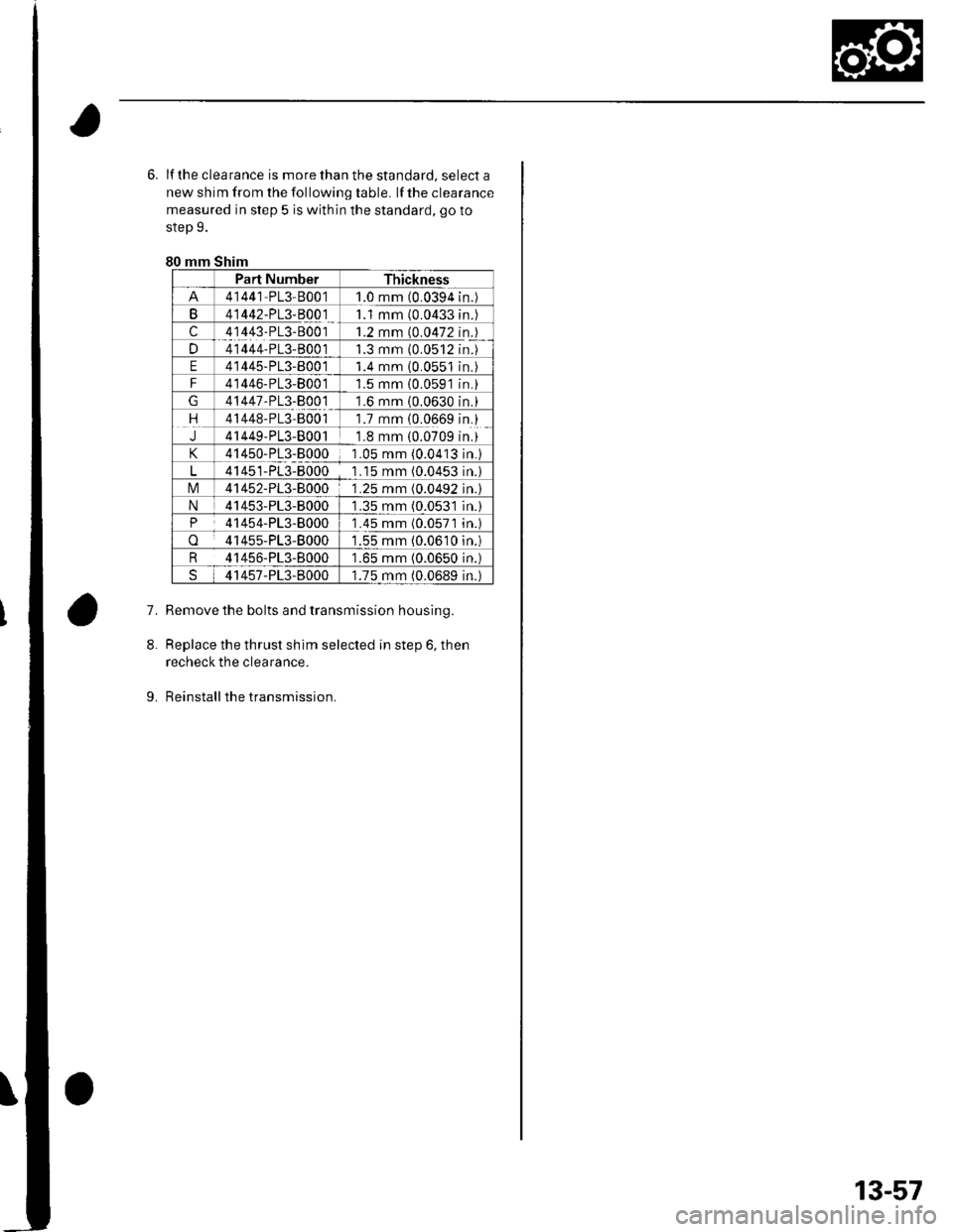
6. lf the clea rance is more than the standard, select a
new shim from the following table. lf the clearance
measured in step 5 is within the standard, go to
step 9.
80 mm Shim
Part NumberThickness
41441 PL3-80011.0 mm (0.0394n.
B41442-PL3-B00111 mm (0.0433n.
c41443-PL3-80011.2 mm (0.0472n.
D41444-PL3-B0011.3 mm {0.0512n.
E41445-PL3-800 11.4 mm 10.0551n.
F41446-PL3-80011.5 mm {0.0591n.
41447-PL3-800 11.6 mm (0.0630n.
rt41448-PL3-B0011.7 mm {0.0669n.
J41449-PL3-80011.8 mm (0.0709n.
41450-PL3-80001 .05 mm (0.0413n.)
41451-PL3-80001 .15 mm (0.0453n.l
tvl41452-PL3-80001.25 mm (0.0492n.l
N41453-PL3-80001.35 mm (0.053'ln.)
P41454-PL3-80001 .45 mm (0.0571n.l
o41455-PL3-80001.55 mm (0.0610n.)
R 41456-PL3-8000'1.65 mm (0.0650 in.)
41457-PL3-80001.75 mm (0.0689 in.)
7.Remove the bolts and transmission housing.
Replace the thrust shim selected in step 6, then
recheck the clearance.
Reinstall the transmission.
8.
9.
13-57
Page 468 of 1139
Driveline/Axle
SpecialTools ............. 16-2
Driveshaft Inspection ......................... 16-3
Driveshafts Removal .......................... 16-3
Driveshafts Disassembly ................... 16-5
Dynamic Damper Replacement ........ 16-8
Driveshafts Reassembly .................... 16-9
Driveshafts lnstallation ...................... 16-17
lntermediate Shaft Removal .............. 16-19
Intermediate Shaft Disassembly ................................. 16-20
lntermediate Shaft Reassembly .................................. 16-22
lntermediate Shaft lnstallation .................................... 16-24
Page 470 of 1139
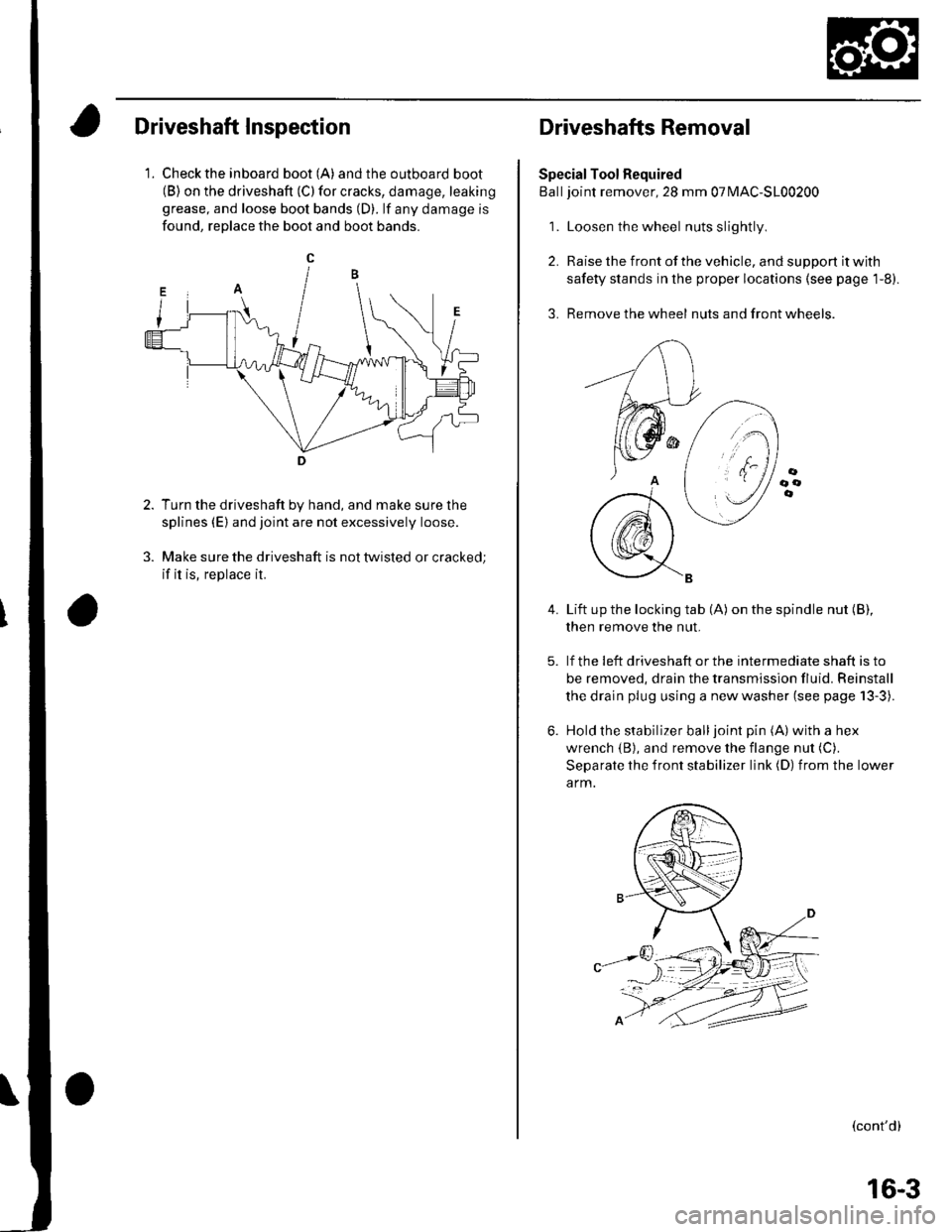
Driveshaft Inspection
1. Check the inboard boot (A) andthe outboard boot(B) on the driveshaft (C) for cracks, damage, leaking
grease, and loose boot bands (D). lf any damage is
found, reDlace the boot and boot bands.
Turn the driveshaft by hand, and make sure the
splines (E) and joint are not excessively loose.
Make sure the driveshaft is not twisted or cracked;
if it is, replace it.
Driveshafts Removal
Special Tool Required
Balljoint remover, 28 mm 07MAC-S100200
1. Loosen the wheel nuts slightly
2. Raise the front of the vehicle, and support it with
safety stands in the proper locations (see page 1-8).
3. Remove the wheel nuts and front wheels.
4.Lift up the locking tab (A) on the spindle nut (B),
then remove the nut.
lf the !eft driveshaft or the intermediate shaft is to
be removed, drain the transmission fluid. Reinstall
the drain plug using a new washer (see page 13-3).
Hold the stabilizer balljoint pin (A) with a hex
wrench {B), and remove the flange nut (C).
Separate the front stabilizer link (D) from the lower
a rm.
(cont'd)
16-3
Page 475 of 1139
Driveline/Axle
9.
Driveshafts Disassembly (cont'dl
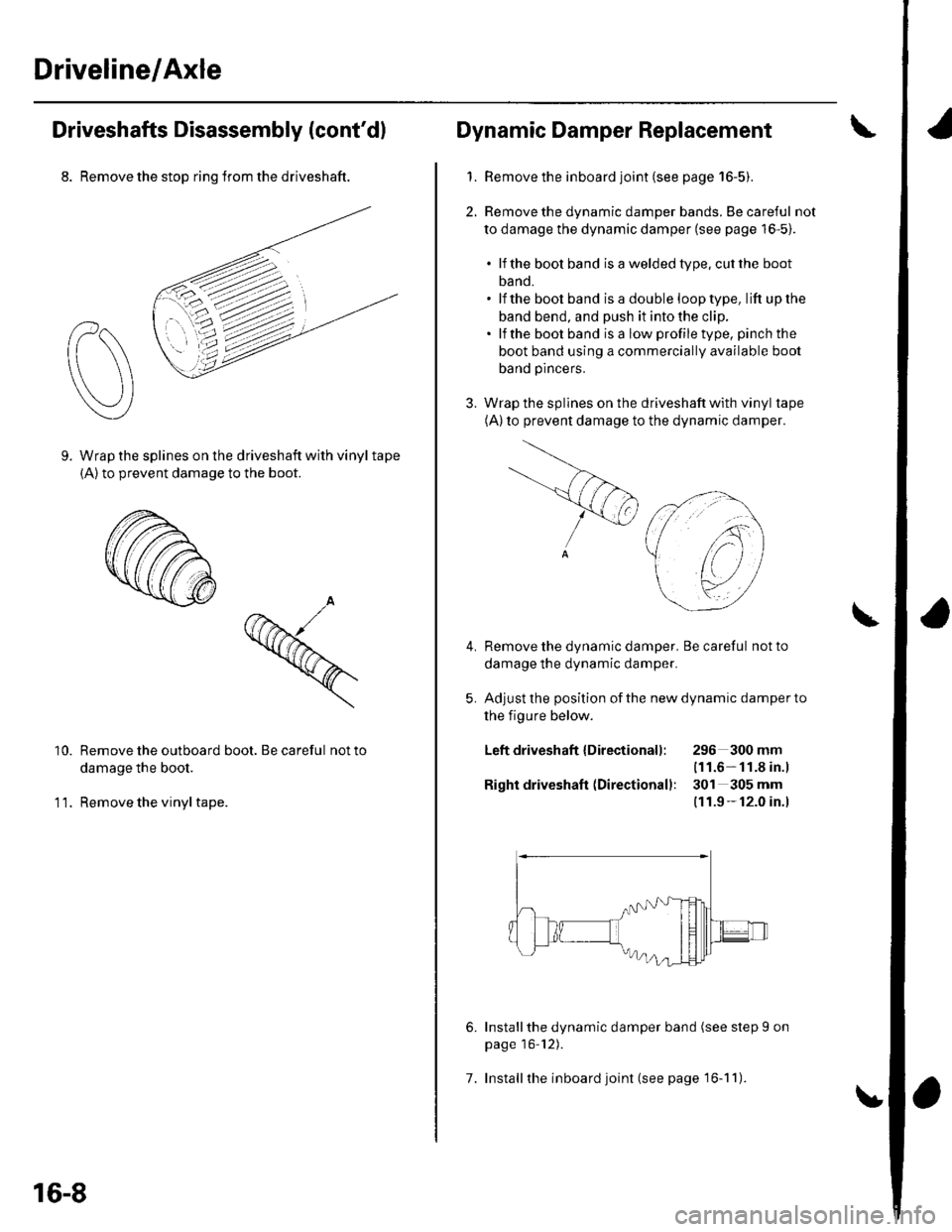
8. Remove the stop ring trom the driveshaft.
Wrap the splines on the driveshaft with vinyl tape(A) to prevent damage to the boot.
Remove the outboard boot. Be careful not to
damage the boot.
Remove the vinyl tape.
10.
11.
16-8
7.
Dynamic Damper Replacement
1. Remove the inboard joint (see page 16-5).
2, Remove the dynamic damper bands. Be careful not
to damage the dynamic damper (see page 16-5).
. lf the bool band isaweldedtype.cutthe boot
band.. lf the boot band isa double looptype, lift upthe
band bend, and push it into the clip.. lfthe boot band is a low profile type, pinch the
boot band using a commercially available boot
band pincers.
3. Wrap the splines on the driveshaft with vinyl tape
(A)to prevent damage to the dynamic damper.
Remove the dynamic damper. Be careful not to
damage the dynamic damper.
Adjust the position of the new dynamic damper to
the figure below.
Left driveshaft {Directionall: 296 300mm(11.6- 11.8 in.)
Right driveshaft (Directionall: 301 305 mm
(11.9 - 12.0 in.l
5.
6.Installthe dynamic damper band (see step I on
page 16'12).
Install the inboard joint (see page 16-1 1).
Page 480 of 1139
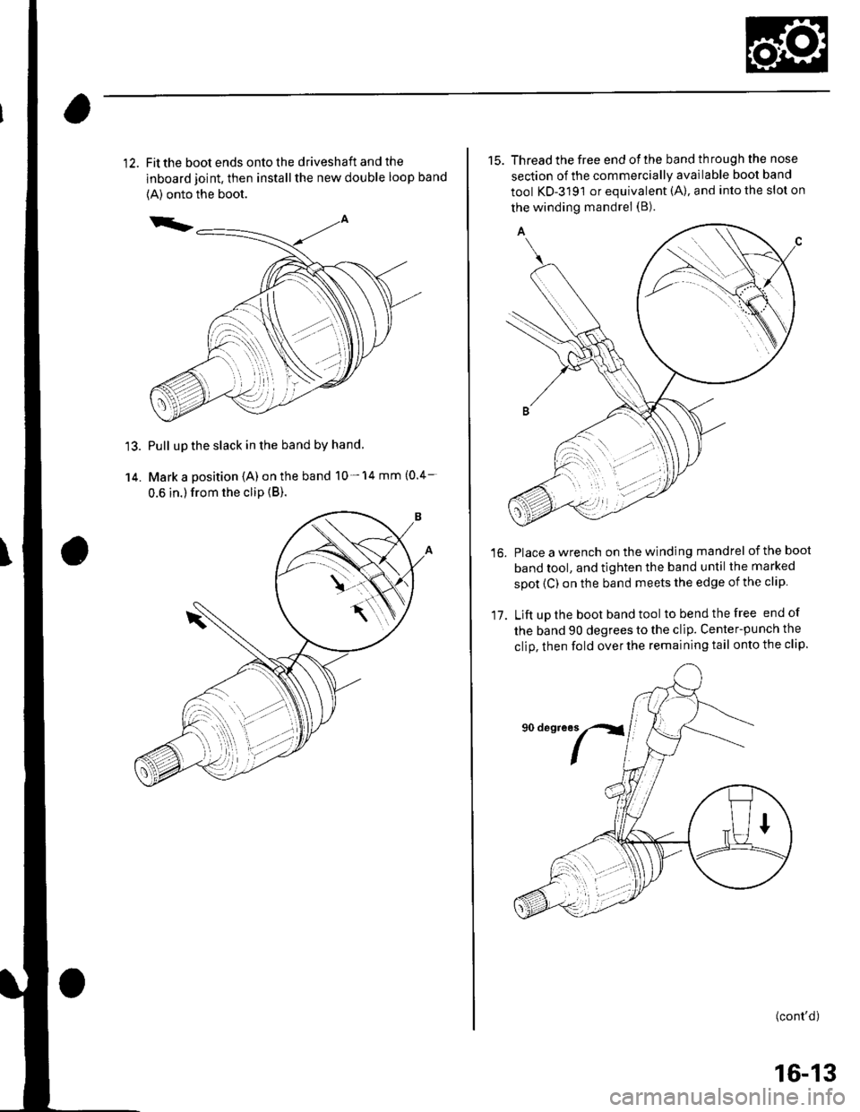
Fit the boot ends onto the driveshaft and the
inboard joint, then install the new double loop band
{A) onto the boot.
Pull up the slack in the band by hand
Mark a position (A) on the band 10- 14 mm (0.4-
0.6 in.) from the clip {B).
15. Thread the free end ofthe band through the nose
section of the commercially available boot band
tool KD-3191 or equivalent (A), and into the slot on
the winding mandrel (B).
Place a wrench on the winding mandrel of the boot
band tool, and tighten the band until the marked
spot (C) on the band meets the edge of the clip
Lift uD the boot band tool tobendthefree end of
the band 90 degrees to the clip. Center-punch the
clio, then fold over the remaining tail onto the clip.
16.
17.
(cont'd)
16-13
Page 482 of 1139
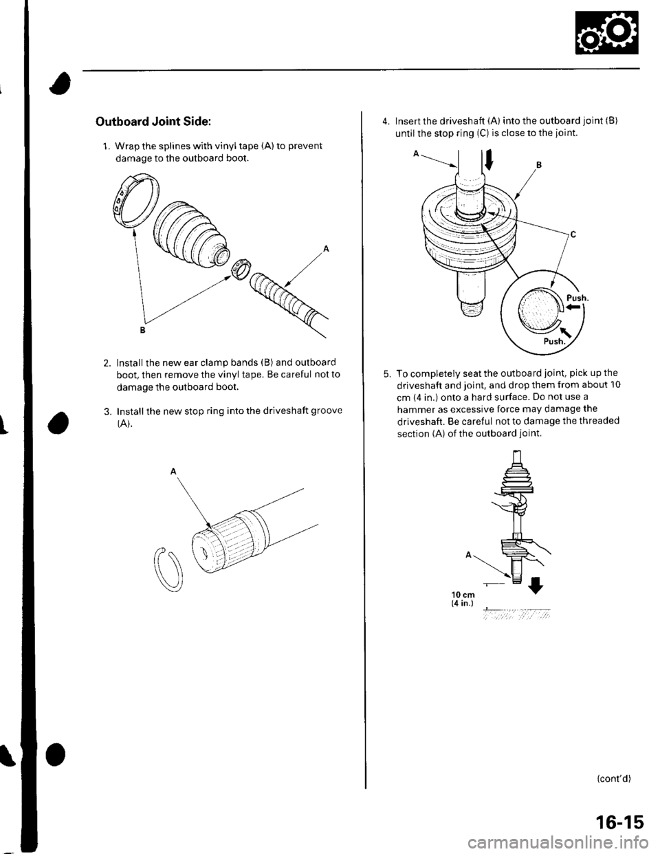
Outboard Joint Side:
1. Wrap the splines with vinyl tape (A) to prevent
damage to the outboard boot.
Installthe new ear clamp bands (B) and outboard
boot, then remove the vinyl tape. Be careful not to
damage the outboard boot.
Install the new stop ring into the driveshaft groove
(A).3.
t
4. Insert the driveshaft (A) into the outboard joint (B)
until the stop ring (C) is close to the joint.
To completely seat the outboard joint, pick up the
driveshaft and joint, and drop them from about 10
cm (4 in.) onto a hard surface. Do not use a
hammer as excessive force may damage the
driveshaft. Be careful not to damage the threaded
section (A) of the outboard joint.
5.
10 cm(4 in.)
- ..,..,1 ;,t ,:-,;
{cont'd)
16-15
Page 485 of 1139
Driveline/Axle
Driveshafts Installation (cont'd)
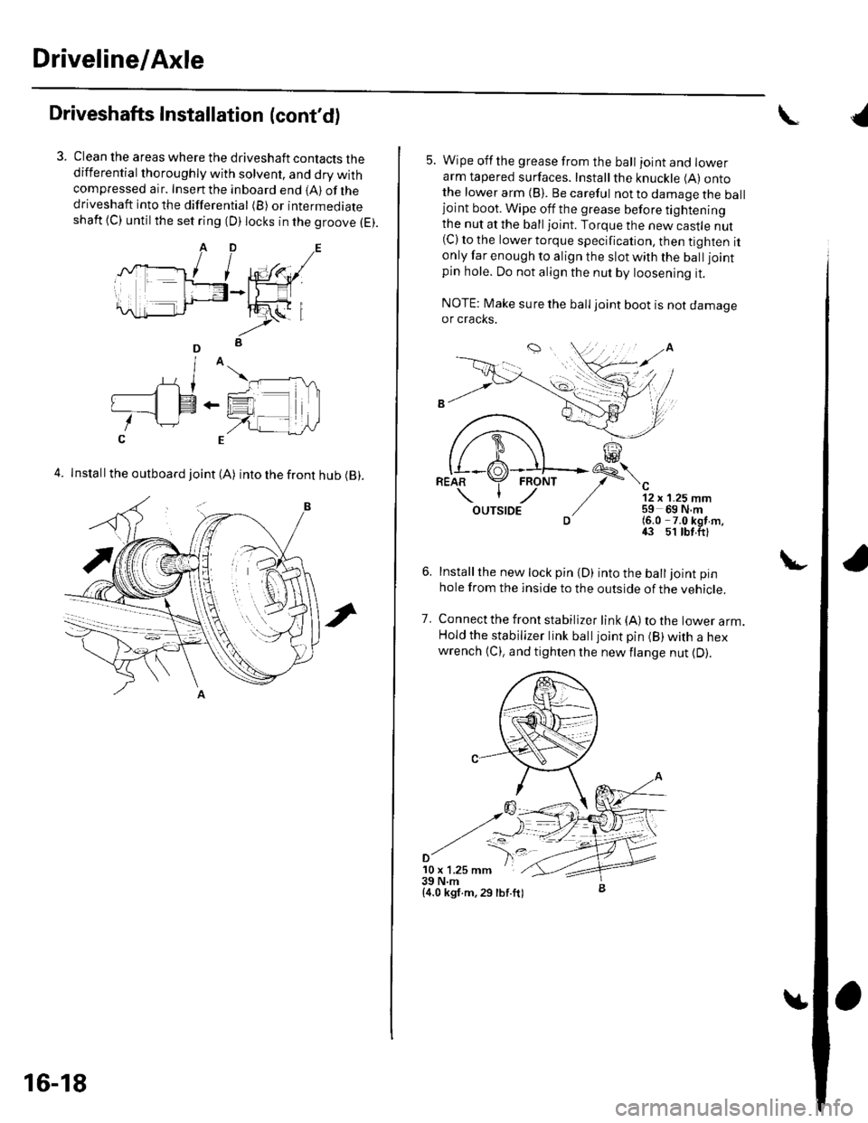
Clean the areas where the driveshaft contacts thedifferential thoroughly with solvent, and dry withcompressed air. Insenthe inboard end {A) ofthedriveshaft into the differential (B) or intermediateshaft {C) until the set ring (D) locks in the groove (E).
4. Install the outboard joint (A) into the front hub (B).
16-18
5. Wipe offthe grease from the ball ioint and lowerarm tapered surfaces. Installthe knuckle (A) ontothe lower arm {B). Be careful not to damage the balljoint boot. Wipe off the grease before tighteningthe nut at the ball joint. Torque the new castle nut(C) to the lower torque specification, then tighten itonly far enough to align the slot with the ball joint
pin hole. Do not align the nut by loosening it.
NOTE: Make sure the ball joint boot is not damageor cracks.
"-'t-
12 x 1.25 mm59 69 N.m(6.0 -7.0 kgf m,43 51 tbt.ftl
Installthe new lock pin {D) into the balljoint pin
hole from the inside to the outside of the vehicle.
Connect the front stabilizer link {A) to the lower arm.Hold the stabilizer link balljoint pin (B) with a hexwrench {C), and tighten the newflange nut {D).
7.
'10 x 1.25 mm39 N.m{4.0 kgf.m,29 lbf.ft)
{