Start HONDA CIVIC 2003 7.G Owner's Guide
[x] Cancel search | Manufacturer: HONDA, Model Year: 2003, Model line: CIVIC, Model: HONDA CIVIC 2003 7.GPages: 1139, PDF Size: 28.19 MB
Page 188 of 1139
lntake Manifold and Exhaust System
Intake Manifold Removal and Installation (cont'd)
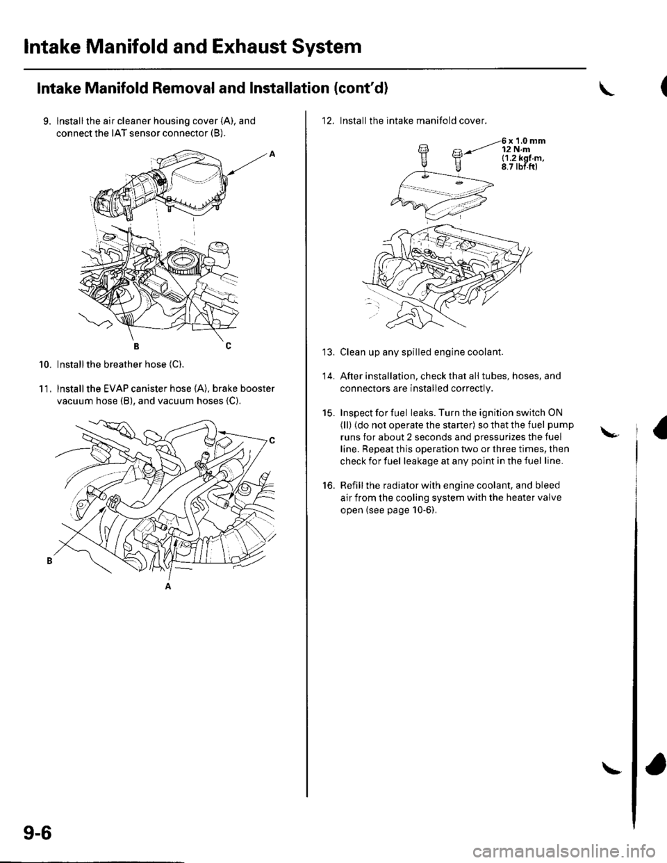
9. lnstallthe air cleaner housing cover (A), and
connect the IAT sensor connector (B).
BC
Installthe breather hose (C).
lnstallthe EVAP canister hose (A), brake booster
vacuum hose (B), and vacuum hoses {C).
10.
11.
9-6
\
12. Installthe intake manifold cover.
6x1.0mm12 N.ml.1.2k91.m,8.7 tbf.ftl
Clean up any spilled engine coolant.
After installation, check that all tubes, hoses, and
connectors are installed correctly.
Inspect for fuel leaks. Turn the ignition switch ON
(ll) (do not operate the starter) so that the fuel pump
runs for about 2 seconds and pressurizes the fuel
line. Repeat this operation two or three times, then
check for fuel leakage at any point in the fuel line.
Refill the radiator with engine coolant, and bleed
air from the cooling system with the heater valve
open (see page 10-6).
to.
\-
Page 194 of 1139
Cooling System
Fan Motor Test
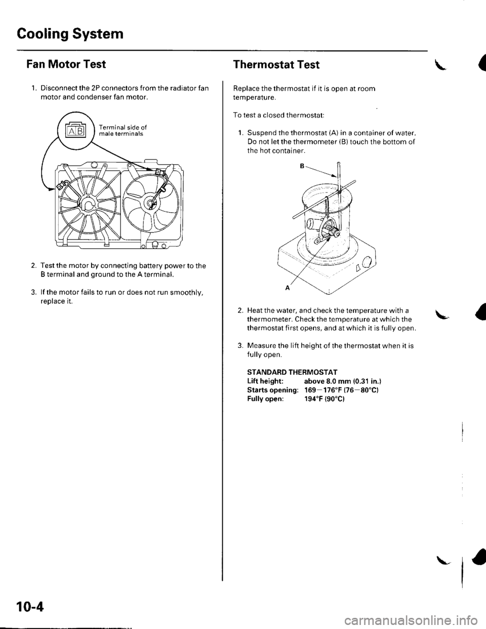
1. Disconnect the 2P connectors from the radiator fan
motor and condenser fan motor.
Test the motor by connecting battery power to the
B terminal and ground to the A terminal.
lf the motor fails to run or does not run smoothly,
reptace rL
10-4
\
Thermostat Test
Replace the thermostat if it is open at room
remperalure.
To test a closed thermostatl
1. Suspend the thermostat (A) in a container of water.
Do not let the thermometer {B) touch the bottom of
the hot container.
(\
2.
3.
Heat the water, and check the temDerature with a
thermometer. Check the temperature at which the
thermostat first opens, and at which it is fully open.
Measure the lift height of the thermostat when it is
fullv ooen.
STANDARD THERMOSTAT
Lift height; above 8.0 mm (0.31 in.)
Starts opening: 169 176"F(76 80"C)
Fully open: 194"F {90'Cl
\.
Page 196 of 1139
Cooling System
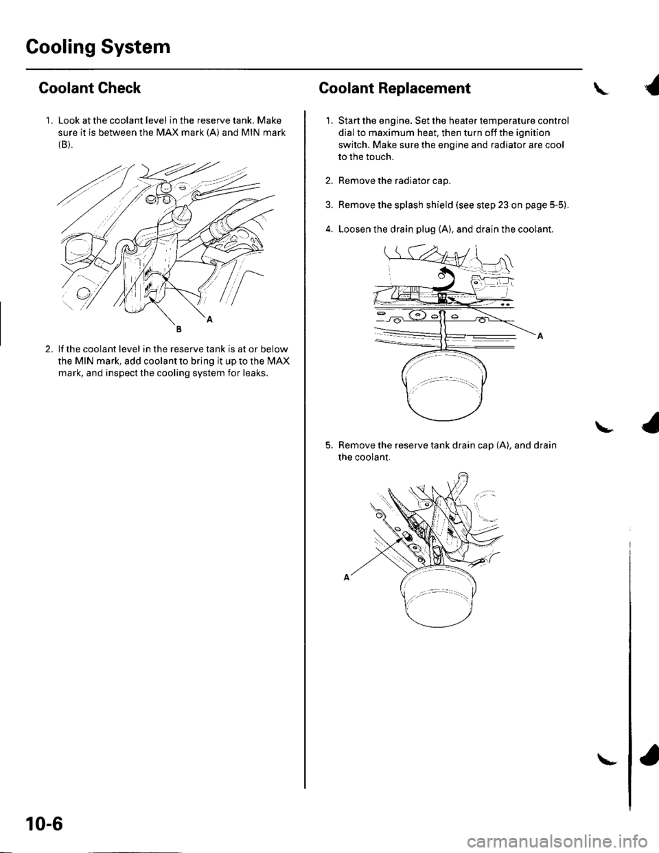
1 . Look at the coolant level in the reserve tank. Make
sure it is between the MAX mark (A) and MIN mark(B),
Goolant Check
lf the coolant level in the reserve tank is at or below
the MIN mark, add coolant to bring it up to the l\4AX
mark, and inspect the cooling system for leaks.
10-6
\-
Coolant Replacement
1.
\
Start the engine. Set the heater temperature control
dial to maximum heat. then turn off the ignition
switch. Make sure the engine and radiator are cool
to the touch.
Remove the radiator cap.
Remove the splash shield (see step 23 on page 5-5).
Loosen the drain plug (A), and drain the coolant.
Remove the reserve tank drain cap (A), and drain
the coolant.
\
Page 197 of 1139
1.
After the coolant has drained, tighten the radiator
drain plug securely. and installthe reserve tank
drain cap securely.
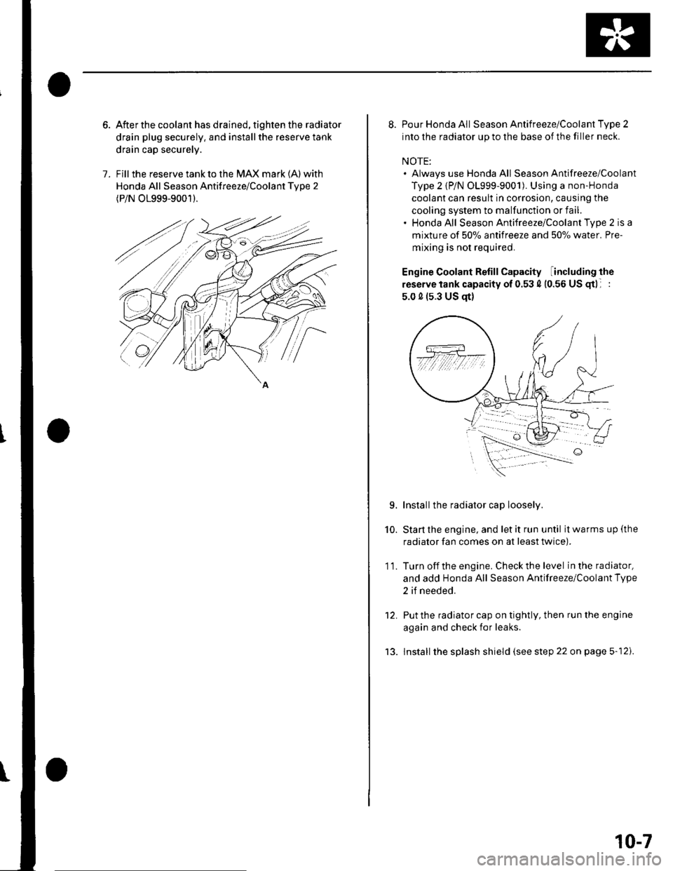
Fill the reserve tank to the MAX mark (A) with
Honda All Season Antifreeze/Coolant Tvpe 2
(P/N O1999-9001).
8. Pour Honda All Season Antifreeze/Coolant Type 2
into the radiator up to the base of the filler neck.
NOTE:. Always use Honda All Season Antifreeze/Coolant
Type 2 {P/N 01999-9001). Using a non-Honda
coolant can result in corrosion, causing the
cooling system to malfunction or fail.. Honda All Season Antifreeze/Coolant Type 2 is a
mixture of 50% antifreeze and 507o water. Pre-
mixing is not required.
Engine Coolant Refill Capacity including the
reserve tank capacity of 0.53 4 (0.56 US gtl :
5.0 0 (s.3 US qt)
Installthe radiator cap loosely.
Start the engine, and let it run until it warms up (the
radiator fan comes on at least twice).
Turn off the engine. Check the level in the radiator,
and add Honda All Season Antifreeze/Coolant Type
2 if needed.
Put the radiator cap on tightly, then run the engine
again and check for leaks.
lnstall the splash shield (see step 22 on page 5-12).
10.
11.
L
tJ.
10-7
Page 210 of 1139
General Troubleshooting Information
Intermittent Failures
The term "intermittent failure" means a svstem mav
have had a failure. but it checks OK now. lf the
Malfunction Indicator Lamp (MlL) on the dash does not
come on, check for Door connections or loose terminals
at all connectors related to the circuit that Vou are
troubleshooting.
Opens and Shorts
"Ooen" and "Short" are common electrical terms. An
open is a break in a wire or at a connection. A short is
an accidental connection of a wire to ground or to
another wire. In simple electronics, this usually means
something won't work at all. With complex electronics(such as ECMs)this can sometimes mean something
works, but not the way it's supposed to.
How to Use the PGM Tester or a Scan Tool
lf the MIL {Malfunction Indicator Lamp} has come on
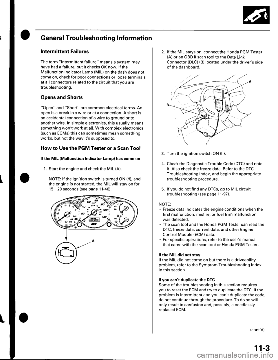
'1. Start the engine and check the MIL {A).
NOTE: lf the ignition switch is turned ON (ll), and
the engine is not started, the MIL will stay on for
15 20 seconds (see page 11-46).
K-> ;"PN/.- -::: - -d V-: !
w:ix&K#
2. lf the MIL stays on, connect the Honda PGM Tester(A) or an OBD ll scan tool to the Data Link
Connector {DLC) (B) located under the driver's side
of the dashboard.
3.
5.
Turn the ignition switch ON (ll).
Check the Diagnostic Trouble Code (DTC) and note
it. Also check the freeze data. Refer to the DTC
Troubleshooting Index, and begin the appropriate
troubleshooting procedure.
lf you do not find any DTCS, go to MIL circuit
troubleshooting (see page 11-97).
NOTE:. Freeze data indicates the engine conditions when the
first malfunction, misfire, or fuel trim malfunction
was detected.. The scan tool and the Honda PGM Tester can read the
DTC, freeze data, current data, and other Engine
Control l\4odule {EClvl) data.. For specific operations, refer to the user's manual
that came with the scan tool or Honda PG l\4 Tester.
lf the MIL did not stay
lf the MIL did not come on but there is a driveability
problem, refer to the Symptom Troubleshooting Index
in this section.
lf you can't duplicate the DTC
Some of the troubleshooting in this section requires
you to reset the ECM and try to duplicate the DTC. lf rhe
problem is intermittent and you can't duplicate the code,
do not continue through the procedure. To do so will
only result in confusion and, possibly, a needlessly
replaced ECM.
(cont'd)
11-3
Page 211 of 1139
Fuel and Emissions Systems
General Troubleshooting Information (cont'dl
How to Reset the ECM
You can reset the ECM in either of two ways:
. Use the OBD ll scantool or Honda PGMTesterto
reset the ECM memory.
See the OBD ll scan tool or Honda PGI\4 Tester user's
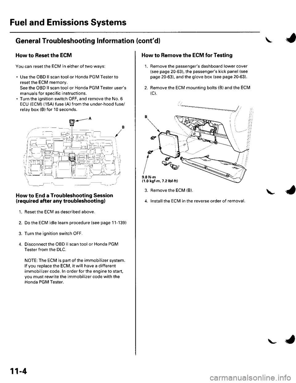
manuals for specific instructions.' Turn the ignition switch OFF, and remove the No. 6
ECU {ECM} (15A) fuse (A)from the under-hood fuse/
relav box (Blfor 10 seconds.
How to End a Troubleshooting Session
(required after any troubleshootingl
1. Reset the ECM as described above.
2. Do the ECM idle learn procedure (see page 11-139)
3. Turn the ignition switch OFF.
4. Disconnectthe OBD ll scan tool or Honda PGM
Tester from the DLC.
NOTE: The ECM is part of the immobilizer system.
lf vou replace the ECM, it will have a different
immobilizer code. In order for the engine to start,
you must rewrite the immobilizer code with the
Honda PGM Tester.
11-4
\- ta
J
How to Remove the ECM for Testing
1. Remove the passenger's dashboard lower cover
{see page 20-63), the passenger's kick panel (see
page 20-63), and the glove box (see page 20-63).
2. Remove the ECM mounting bolts (B) and the ECM
(c),
9.8 N.m{1.0 kgf.m,7.2lbt.ft}
3. Remove the ECM (B).
4. Installthe ECM in the reverse order of removal.
L
Page 213 of 1139
Fuel and Emissions Systems
General Troubleshooting Information (cont'd)
ECM Updating and Substitution for Testing
Special Tools Bequired
Honda Interface Module (HlM) EOS05435570
Use this procedure when you have to substitute a
known-good ECM in a troubleshooting procedure.
U pdate the ECM only if the ECN4 does not already have
the latest software loaded,
NOTE;. lMake sure the battery is fully charged before you
update the ECN4.. To prevent ECM damage during the update, do not
turn the ignition switch OFF, and do not use any of
the vehicle's electrical devices (light, horn, radio, etc. ).
How to Update the ECM
1. Turn the ignition switch ON (ll). Do not startthe
eng Ine.
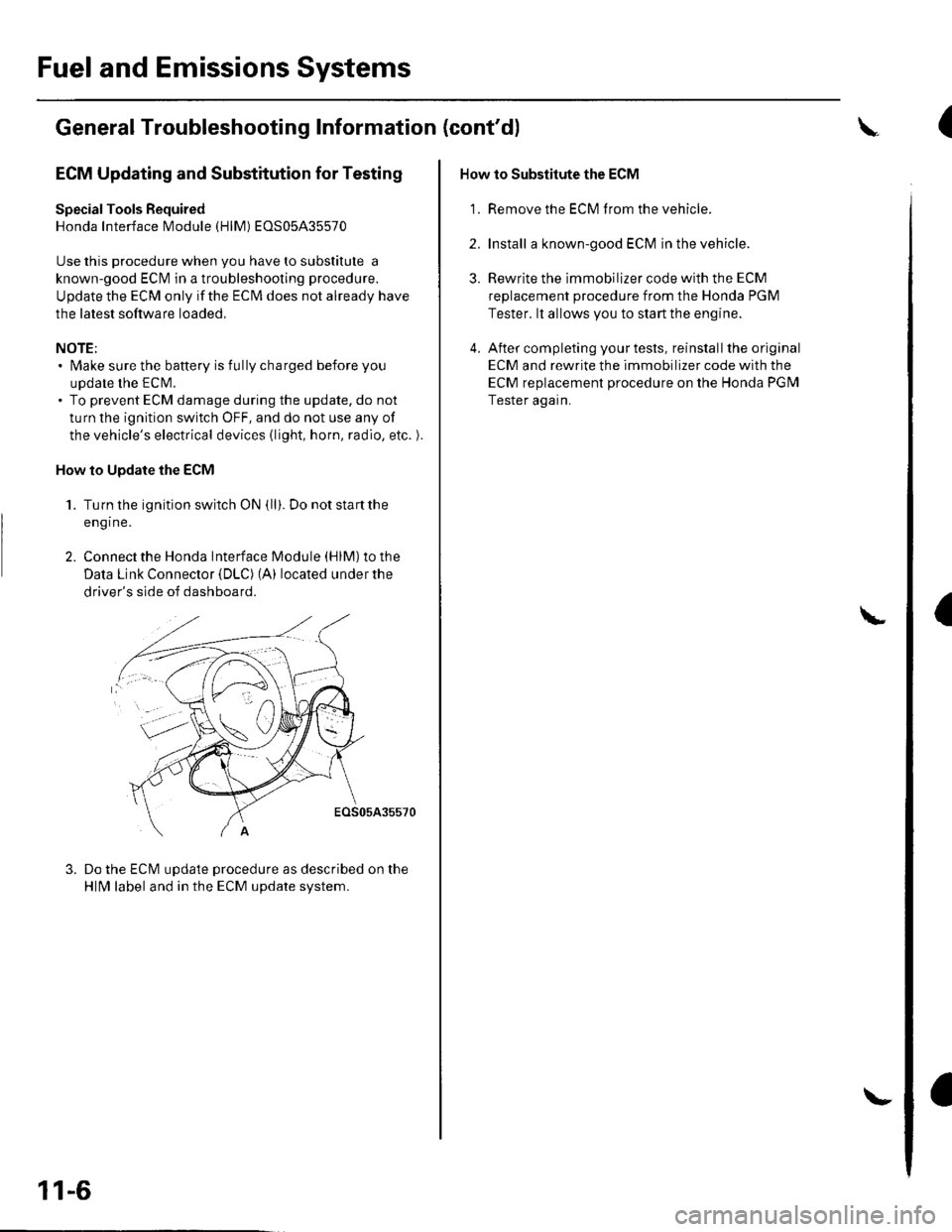
2. Connect the Honda lnterface Module (HlM) to the
Data Link Connector {DLC) (A) located under the
driver's side of dashboard.
EOS05A35570
Do the ECM update procedure as described on the
HlN4 label and in the ECM update system.
11-6
\-
How to Substitute the ECM
'1. Remove the ECM f rom the vehicle.
2. Install a known-good ECM in the vehicle.
3. Rewrite the immobilizer code with the ECM
replacement procedure from the Honda PGM
Tester. lt allows you to start the engine.
4. After completing your tests, reinstall the original
ECM and rewrite the immobilizer code with the
ECM replacement procedure on the Honda PGM
Tester again.
L
(
I
Page 217 of 1139
Fuel and Emissions Systems
Symptom Troubleshooting Index
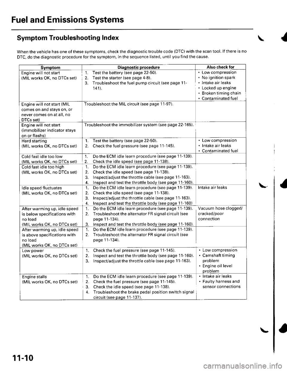
When the vehicle has one of these symptoms, check the diagnostic trouble code (DTC) with the scan tool. lf there is no
DTC, do the diagnostic procedure for the symptom, in the sequence listed, until you find the cause.
SvmotomDiaqnostic procedureAlso check lor
Engine will not sta rt
(MlL works OK, no DTCS set)
1. Test the battery {see page 22-50).
2. Test the starter (see page 4-8).
3. Troubleshoot the fuel pump circult (see page 11
141).
Low compressron
No ignition spark
lntake air leaks
Locked up engine
Broken timing chain
Contaminated fuel
Engine will not start (MlL
comes on and stays on, or
never comes on at all, no
DTCS set)
Troubleshoot the l\4lL circuit (see page 1 '1-97).
Engine will not start
(immobilizer indicator stays
on or flashs)
Troubleshoot the immobilizer system (see page 22-165).
Hard starting(MlL works OK, no DTCS set)
1. Testthe battery (see page 22-50).
2. Checkthe fuel pressure (see page 11-145).
Low compression
Intake air leaks
Contaminated fuel
Cold fast idle too low(MlL works OK. no DTCS set)
1. Do the ECM idle learn procedure (see page 11-139).
2. Checkthe idle sDeed (see paqe 11-138).
Cold fast idle too high
(MlL works OK, no DTCS set)
Do the ECI\4 idle learn procedure (see page 1 1- 139).
Checkthe idle speed {see page 11-138).
Inspect/adjust the throttle cable (see page 1 '1-'163).
Inspect and test the throttle body {see page 1 1-160}.
']�
2.
3.
ldle speed fluctuates
(MlL works OK, no DTCS set)
1. Dothe ECM idle learn procedure (see page 11-'139).
2. Check the idle speed (see page 11-138).
3, Inspecvadjust th e throttle cable (see page 11''163).
4. Insoect and test the throttle bodv (see paqe 11- 160)
Intake air leaks
After warming up, idle speed
is below specifications with
no load
{MlL works OK, no DTCS set)
1. Do the ECIVI idle learn procedure (see page 1 1- 139).
2. Troubleshootthe alternator FR signal circuit (see
page 11-'134).
3. InsDect and test the throttle bodv {see paqe 1 1-160).
Vacuum hose clogged/
cracked/poor
connectron
After warming up, idle speed
is above specifications with
no toao(MlL works OK. no DTCS set)
1. Do the ECM idle learn procedure {see page 1'j-139).
2. Troubleshoot the alternator FR signal circuit(see
page 11-134).
Low power
(MlL works OK, no DTCS set)
1. Check the fuel pressure(seepagell-145).
2. Inspect and test the th roftle body (see page 11-160).
3. Inspecvadjust the throttle cable (see page 11-'163).
Low compressron
Camshaft timing
problem
Engine oil levelprootem
Engine stalls(MlL works OK. no DTCS set)
1. Do the ECM idle learn procedure (see page 1'l'139).
2. Check the fuel pressure{seepagell-145).
3. Check the idle speed (see page I 1-138).
4. Troubleshootthe brake pedal position switch signal
circuit (see paqe 11-137).
lntake air leaks
Faulty harness and
sensor connections
\
\-
11-10
\-
Page 234 of 1139
lgnition Timing Control
The ECM contains the memory for basic ignition timing
at various engine speeds and manifold absolute
pressure. lt also adjusts the timing according to engine
coolant temperature.
Iniector Timing and Duration
The ECM contains the memory for basic discharge
duration at various engine speeds and manifold
pressures. The basic discharge duration, after being
read out from the memory, is further modified by
signals sent from various sensors to obtain the final
discharge duration.
By monitoring long term fuel trim, the ECM detects long
term malfunctions in the fuel system and sets a
Diagnostic Trouble Code {DTC).
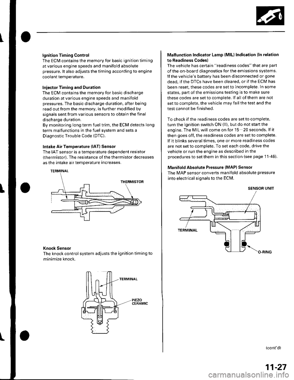
Intake Air Temperature (lAT) Sensor
The IAT sensor is a temperature dependent resistor
{thermistor). The resistance of the thermistor decreases
as the intake air temDerature increases.
Knock Sensor
The knock control system adjusts the ignition timing to
minimize knock.
PIEZOCERAMIC
Malfunction Indicator Lamp lMlLl Indication {ln relation
to Readiness Codes)
The vehicle has certain "readiness codes" that are part
of the on-board diagnostics for the emissions systems.
lf the vehicle's baftery has been disconnected or gone
dead. if the DTCS have been cleared, or if the ECM has
been reset. these codes are set to incomplete. In some
states, part of the emissions testing is to make sure
these codes are set to comDlete. lf all of them are not
set to complete, the vehicle may fail the test and the
test cannot be finished.
To check if the readiness codes are set to complete,
turn the ignition switch ON (ll). but do not start the
engine.TheMILwill comeonforlS 20seconds. lf it
then goes off, the readiness codes are set to complete,
lf it blinks severaltimes, one or more readiness codes
are not set to comolete. To set each code, drive the
vehicle or run the engine as described in the
procedures to set them in this section (see page 1 1-46).
Manifold Absolute Pressure {MAP) Senso]
The MAP sensor converts manifold absolute pressure
into electrical signals to the ECM.
SENSOR UNIT
(cont'd)
11-27
Page 235 of 1139
Fuel and Emissions Systems
(
(
(
System Descriptions (cont'dl
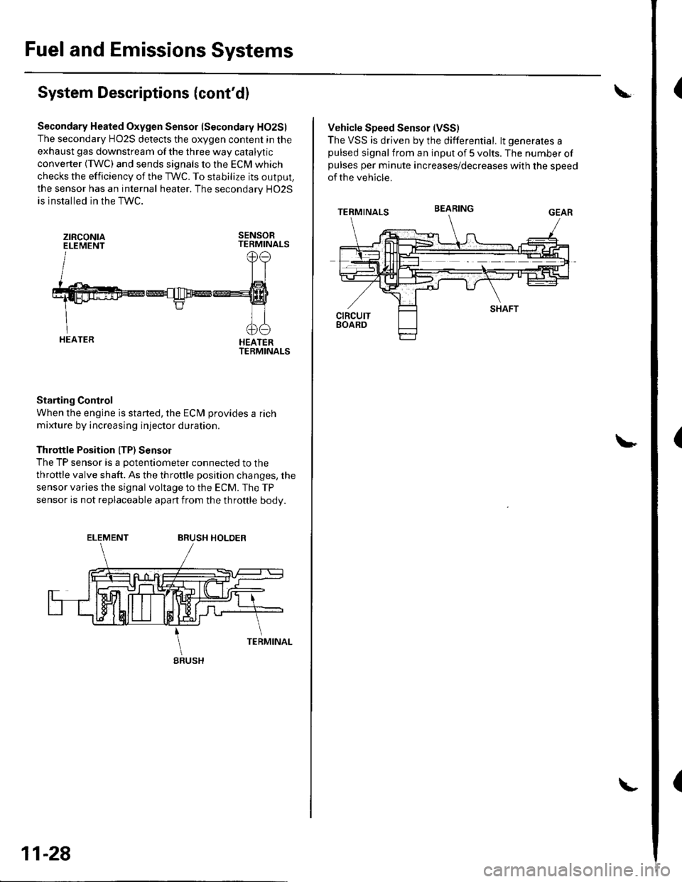
Secondary Heated Oxygen Sensor (Secondary HO2S)
The secondary HO2S detects the oxygen content in the
exhaust gas downstream of the three way catalytic
converter (TWC) and sends signals to the ECM which
checks the efficiency of the TWC. To stabilize its output,
the sensor has an internal heater. The secondarv HO2S
is installed in the TWC.
ztRcoNtaELEMENTSENSORTERMINALS
HEATERTERMINALS
Starting Control
When the engine is started, the ECM provides a rich
mixture by increasing injector duration.
Throttle Position ITP) Sensor
The TP sensor is a potentiometer connected to the
throttle valve shaft. As the throttle position changes, the
sensor varies the signal voltage to the ECM. The TP
sensor is not replaceable apart from the throftle body.
ELEMENTBRUSH HOLDER
gRUSH
11-28
Vehicle Speed Sensor (VSS)
The VSS is driven by the differential. lt generates apulsed signal from an input of 5 volts. The number ofpulses per minute increases/decreases with the speed
of the vehicle.
BEARING