Start HONDA CIVIC 2003 7.G Owner's Manual
[x] Cancel search | Manufacturer: HONDA, Model Year: 2003, Model line: CIVIC, Model: HONDA CIVIC 2003 7.GPages: 1139, PDF Size: 28.19 MB
Page 59 of 1139
Gharging System
Charging Circuit Troubleshooting (cont'd)
6. Start the engine. Hold the engine at 3,000 rpm with
no load (in Neutral) until the radiator fan comes on,
then let it idle.
7. Raise the engine speed to 2,000 rpm, and hold it
there.
8. Turn the headlights (high beam) on, and measure
voltage at the under-hood fuse/relay box terminal.
ls the voltage between 13.9 and 15.1 v?
YES-Go to step 9.
NO Repair or replace the alternator components
(see page 4-30).1
9. Read the amperage at '13.5 V.
NOTE: Adjust the voltage by turning the blower
motor, rear window defogger, brake lights. etc. ON.
ls the amperage 604 ot morc?
YES-Alternator/regulator operation is OK. I
NO Repair or replace the alternator components(see page 4-30).1
4-24
\,
Alternator Control System Test
NOTE: After troubleshooting, perform the engine
control module (ECM) idle learn procedure (see page
11-139).
1 . Check for proper operation of the electrical load
detector (ELD) by checking the malfunction
indicator lamp (MlL) (see page 1 l-3). lf a DTC is
present, diagnose and repair the cause before
continuing with this test.
2. Disconnect the engine wire harness 6P connector
from the starter sub harness 6P connector.
3. Start the engine, and turn the headlights (high
beam) ON,
4. Measure voltage between the engine wire harness
6P connector terminal No. 2 and the positive
terminal of lhe battery.
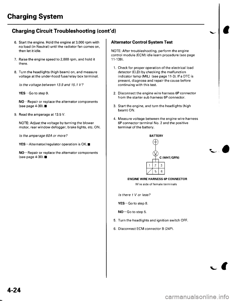
C {WHT/GRN)
ENGINE WIRE HARNESS 6P CONNECTOR
Wire side of female terminals
ls there 1 V or less?
YES Go to step 8.
NO-Go to step 5.
Turn the headlights and ignition switch OFF.
Disconnect ECM connector B (24P).
5.
6.
BATTERY
Page 60 of 1139
\
L
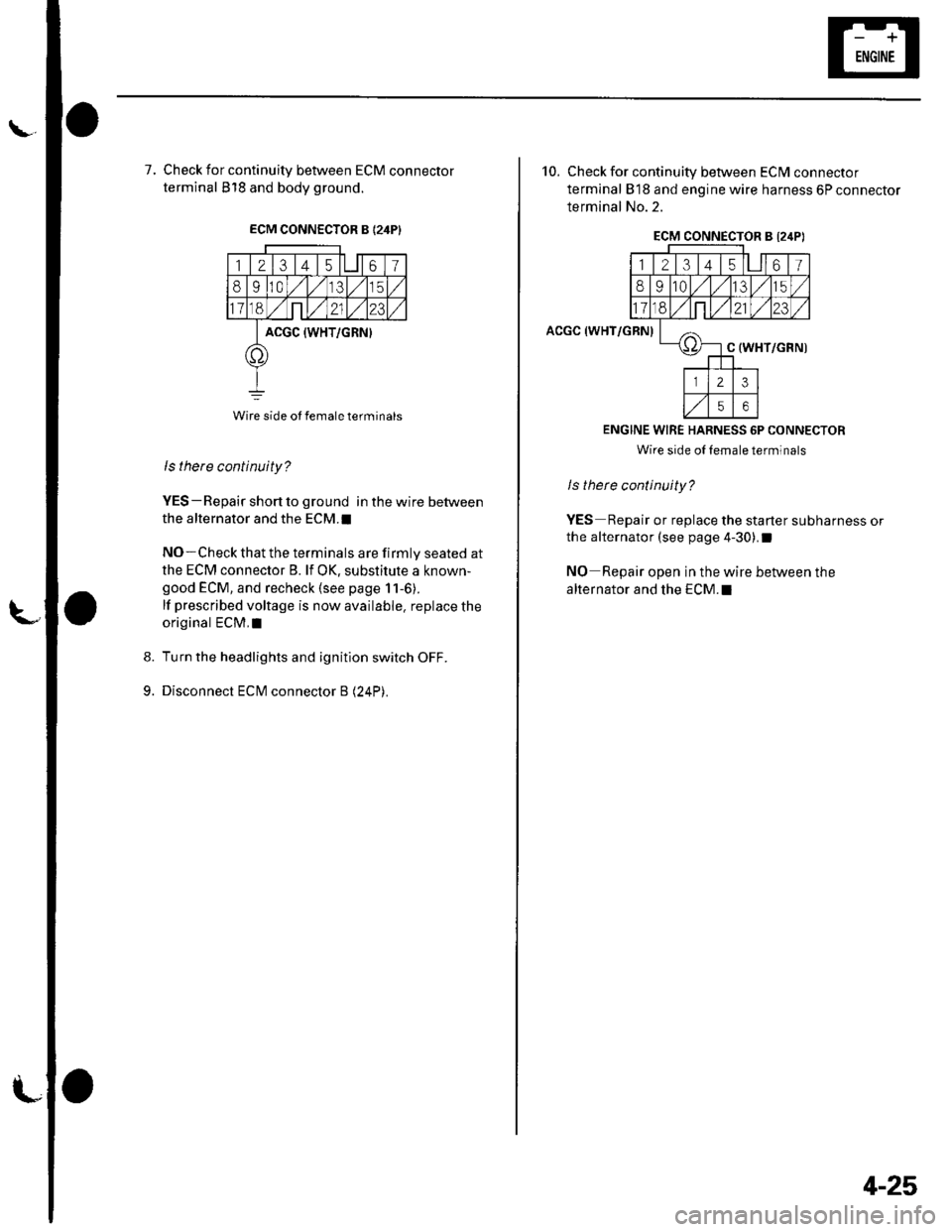
7, Check for continuity between ECM connector
terminal 818 and body ground.
ECM CONNECTOR B {24PI
123 t4 t561
8910,/1,/35
11ont,/2123
ACGC {WHT/GRN}
o
Wire side ot female terminals
9.
ls there continuity?
YES-Repair short to ground in the wire between
the alternator and the ECM.I
NO-Check that the terminals are firmly seated at
the ECM connector B. lf OK, substitute a known-
good ECM, and recheck (see page 11-6).
lf prescribed voltage is now available. replace the
original ECM,I
Turn the headlights and ignition switch OFF.
Disconnect ECM connector B (24P).
10. Check for continuity between ECM connector
terminal 818 and engine wire harness 6P connector
terminal No.2.
ACGC (WHT/GRN)
ECM CONNECTOR B l2,lPI
12314l5lll67
8910t.)15
11on2123
oC (WHT/GRN)
23
56
ENGINE WIRE HARNESS 6P CONNECTOR
Wire side oI lemale terminals
ls therc continuity?
YES Repair or replace the starter subharness or
the alternator (see page 4-30).I
NO Repair open in the wire between the
alternator and the ECM.I
4-25
Page 62 of 1139
\Drive Belt Auto-tensioner Inspection
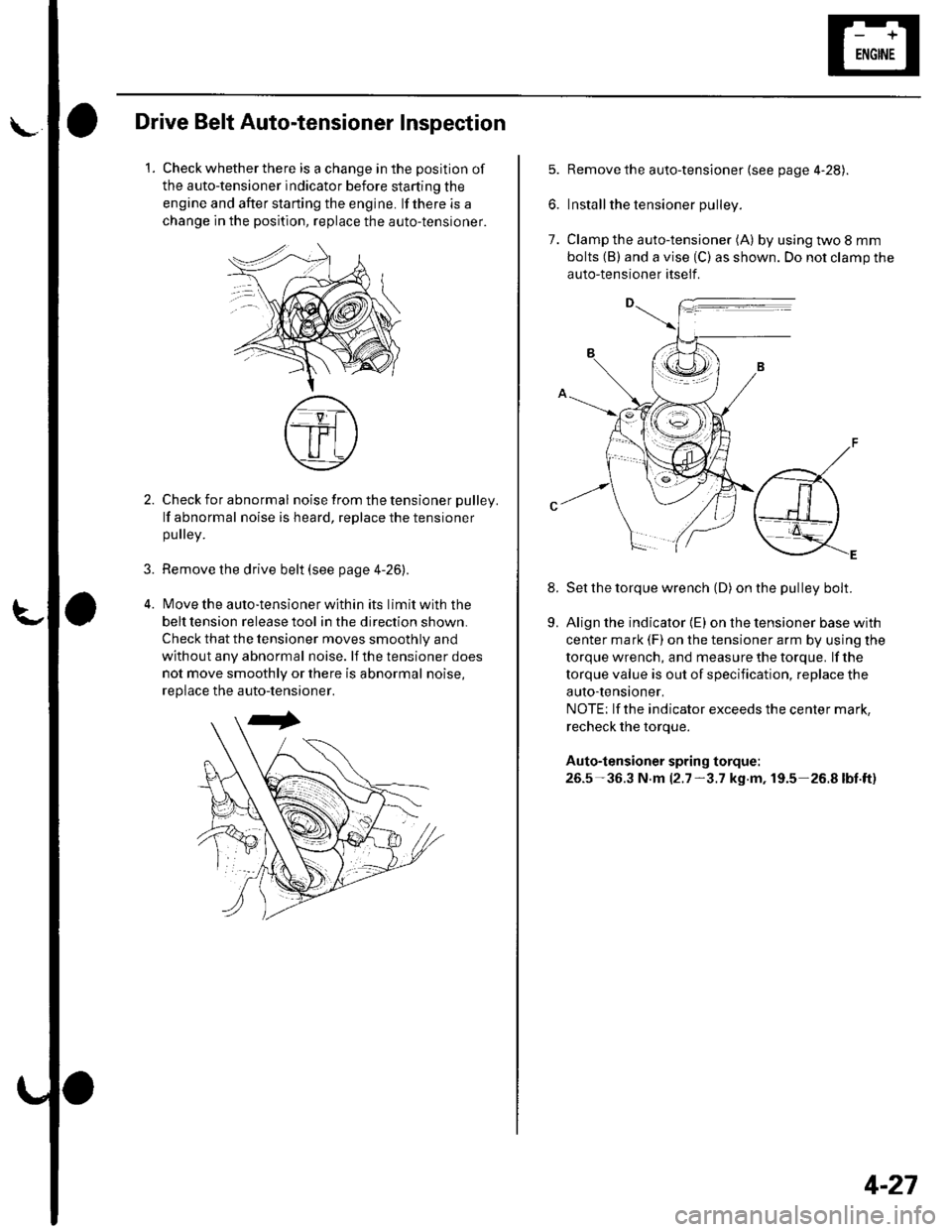
1.Check whether there is a change in the position of
the auto-tensioner indicator before starting the
engine and after starting the engine. lf there is a
change in the position, replace the auto-tensioner.
3.
Check for abnormal noise from the tensioner pulley.
lf abnormal noise is heard, replace the tensioner
pulley.
Remove the drive belt (see page 4-26).
lMove the auto-tensioner within its limit with the
belt tension release tool in the direction shown.
Check that the tensioner moves smoothly and
without any abnormal noise. lf the tensioner does
not move smoothly or there is abnormal noise,
replace the auto-tensioner.
7.
8.
Remove the auto-tensioner (see page 4-28).
Install the tensioner pulley.
Clamp the auto-tensioner (A) by using two 8 mm
bolts (B) and a vise (C) as shown. Do not clamp the
auto-tensioner itself .
Set the torque wrench (D) on the pulley bolt.
Align the indicator {E) on the tensioner base with
center mark (F) on the tensioner arm by using the
torque wrench, and measure the torque. lf the
torque value is out of specification, replace the
auto-tensioner,
NOTE; lf the indicator exceeds the center mark,
recheck the torque.
Auto-tensioner spring torque:
26.5-36.3 N.m 12.7-3.7 kg.m, 19.5-26.8lbt.ft)
9.
4-27
Page 72 of 1139
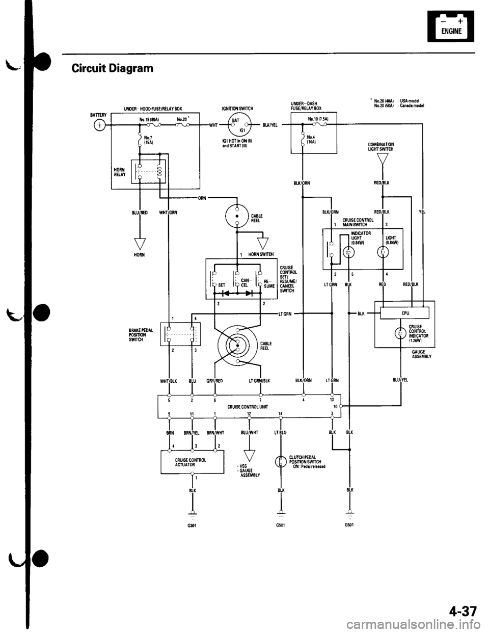
Circuit Diagram
' No.aloAl USAnod.lNo.20 itoAl C.md! modrlUISEF NOOD fUS'/iILAY IOX
-to ots BU/YIL
lcl H0Tii0llilllmdSTARTlllll
1 Honilsffroi
CTuICII PEDALP0sm0 swtrct
26 1113cnu6E coNTnoL uNtT l0
4-37
Page 80 of 1139
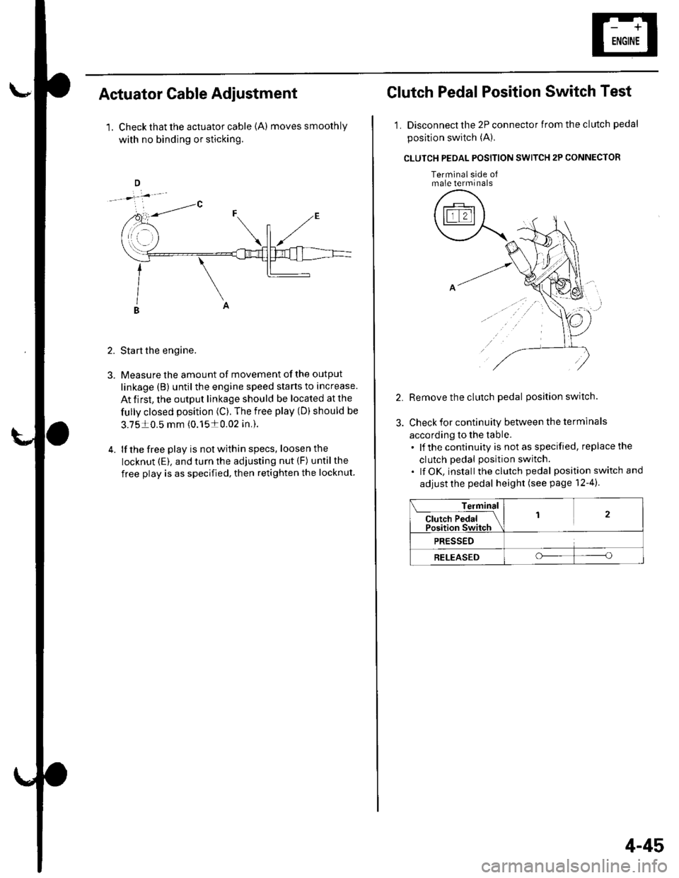
Actuator Cable Adiustment
1. Check that the actuator cable {A) moves smoothly
with no binding or sticking.
2. Start the engine.
3. Measure the amount of movement of the output
linkage (B) until the engine speed starts to increase.
At first, the output linkage should be located at the
fully closed position (C). The free play (D) should be
3.7510.5 mm (0.1510.02 in,).
4. lf the free play is not within specs, loosenthe
locknut (E). and turn the adjusting nut (F) untilthe
free play is as specified, then retighten the locknut
Clutch Pedal Position Switch Test
1. Disconnect the 2P connector from the clutch pedal
position switch (A),
CLUTCH PEOAL POSITION SWITCH 2P CONNECTOR
Terminalside ofmale terminals
Remove the clutch pedal position switch.
Check for continuity between the terminals
according to the table.. lf the continuity is not as specified, replace the
clutch pedal position switch.. lf OK, install theclutch pedal position switch and
adjust the pedal height (see page 12-4).
Terminal
Cl"t"h P"d"l IPosition Switch
12
PRESSED
RELEASEDoo
4-45
Page 95 of 1139
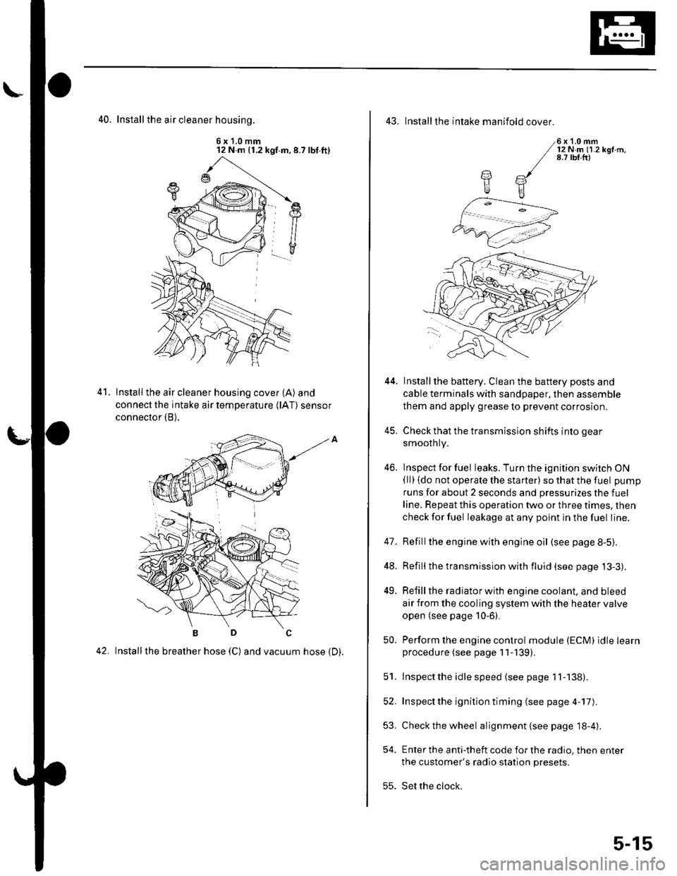
40. Install the air cleaner housinq.
6x1.0mm12 N m (1.2 kgf.m,8.7 lbt.ft)
Install the air cleaner housing cover (A) and
connect the intake air temperature (lAT) sensor
connector (B),
42. Installthe breather hose (C) and vacuum hose 1D).
41.
43. Installthe intake manifold cover.
6x1.0mm12Nm11.2kgf.m.8.7 tbf.ft)
Installthe battery. Clean the battery posts and
cable terminals with sandpaper, then assemble
them and apply grease to prevent corrosion.
Check that the transmission shifts into gear
smoothly.
Inspect for fuel leaks. Turn the ignition switch ON(ll) {do not operate the starter) so that the fuel pump
runs for about 2 seconds and pressurizes the fuel
line. Repeat this operation two or three times, then
check for fuel leakage at any point in the fuel line.
Refillthe engine with engine oil (see page 8-5).
Refill the transmission with fluid (see page 13-3).
Refill the radiator with engine coolant, and bleed
air from the cooling system with the heater valve
open (see page 10-6).
Perform the engine control module (ECM) idle learnprocedure (see page 11-139).
Inspect the idle speed (see page 1 1-138).
Inspect the ignition timing (see page 4-17).
Check the wheel alignment {see page 18-4).
Enter the anti-theft code for the radio, then enter
the customer's radio station presets.
Set the clock.
YE
44.
41.
]tE
46.
48.
49.
52.
53.
54.
50.
51.
55.
5-15
Page 101 of 1139
Cylinder Head
Engine Compression Inspection
1. Warm up the engine to normal operating
temperature (cooling fan comes on).
2. Turn the ignition switch OFF.
3. Remove the intake manifold cover (see step 1 onpage 6-22).
4, Disconnect all four injector connectors.
5. Start the engine, and let it run until it stalls.
6. Remove the iour ignition coils (see page 4-18).
7. Remove the four spark plugs.
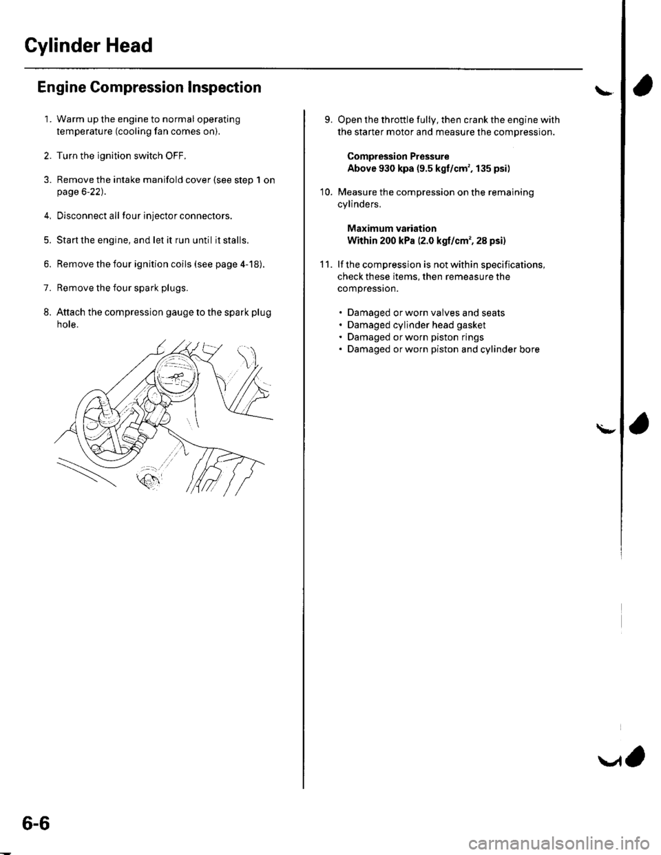
8. Attach the compression gauge to the spark plug
note.
6-6
V,
\
9.
10.
Open the throttle fully, then crank the engine with
the starter motor and measure the compression.
Compression Pressure
Above 930 kpa (9.5 kgf/cm', 135 psi)
Measure the compression on the remaining
cylinders,
Maximum vadation
Within 200 kPa (2.0 kgf/cm', 28 psi)
lf the compression is not within specifications,
check these items, then remeasure the
compressron.
. Damaged orworn valves and seats. Damaged cylinder head gasket. Damaged or worn piston rings. Damaged orworn piston and cylinder bore
11.
\-
Page 136 of 1139
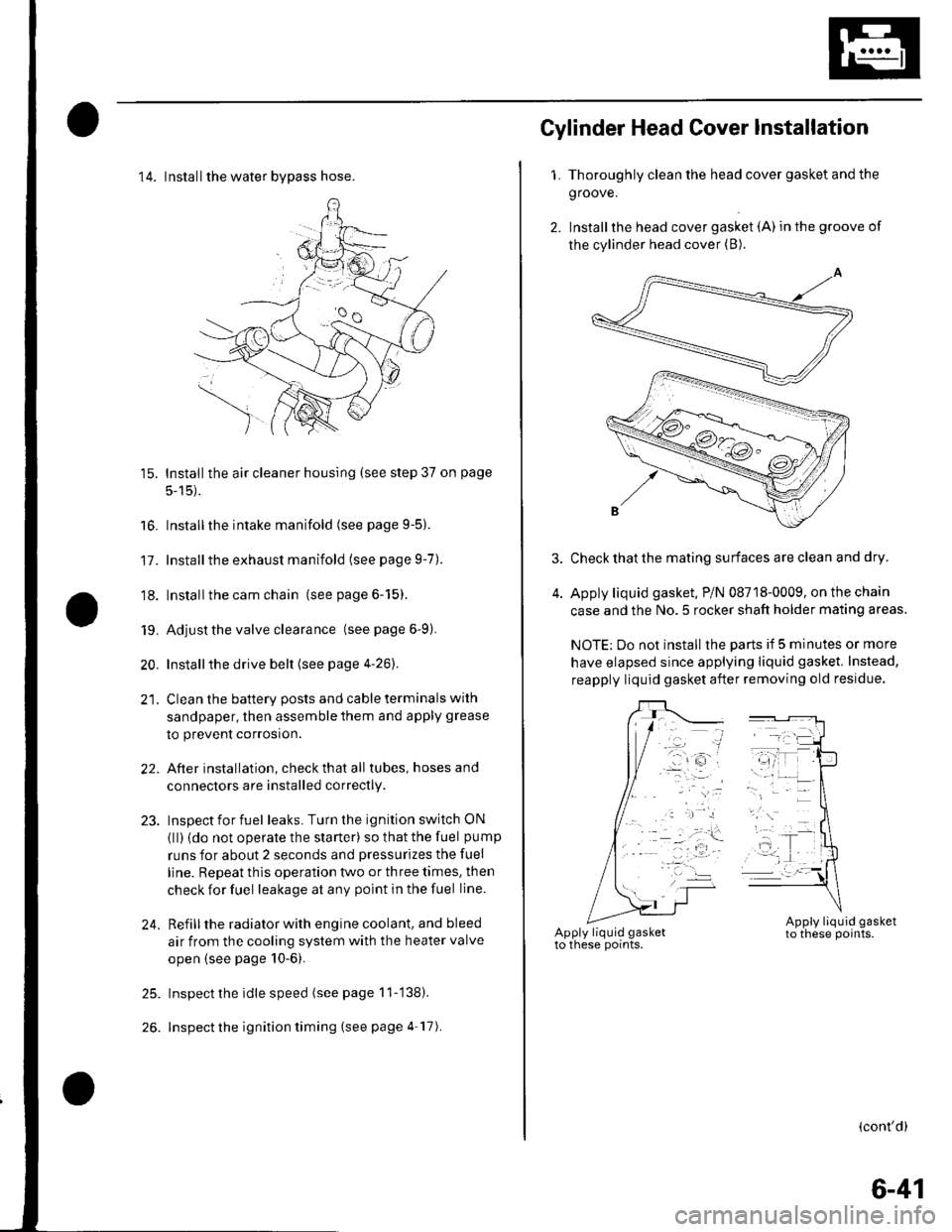
14. Installthe water bvpass hose.
15. Installthe air cleaner housing (see step 37 on page
5-15).
16. Installthe intake manifold (see page 9-5).
17. Installthe exhaust manifold (see page 9-7).
'18. Installthe cam chain (see page 6-15).
19. Adjust the valve clearance (seepage6-9).
20. Installthe drive belt (see page 4-26).
21. Clean the battery posts and cable terminals with
sandpaper, then assemble them and apply grease
to prevent corrosion.
22. After installation, checkthatall tubes, hosesand
connectors are installed correctly.
23. Inspectforfuel leaks. Turn the ignition switch ON
{ll) {do not operate the starter) so that the fuel pump
runs for about 2 seconds and pressurizes the fuel
line. Repeat thls operation two or three times, then
check for fuel leakage at any point in the fuel line.
24. Refillthe radiator with engine coolant, and bleed
air from the cooling system with the heater valve
open (see page 10-6).
25. Inspect the idle speed (see page 11-'138).
26. Inspect the ignition timing (see page 4-17).
Gylinder Head Cover lnstallation
1. Thoroughly clean the head cover gasket and the
groove.
2. Installthe head cover gasket (A) in the groove of
the cylinder head cover (B).
Check that the mating surfaces are clean and dry.
Apply liquid gasket. P/N 08718-0009, on the chain
case and the No.5 rocker shaft holder mating areas.
NOTE: Do not install the parts if 5 minutes or more
have elapsed since applying liquid gasket. Instead,
reapply liquid gasket after removing old residue.
(cont'd)
6-41
Page 144 of 1139
Engine Block
Crankshaft Main Bearing Replacement
Main Bearing Clearance Inspection
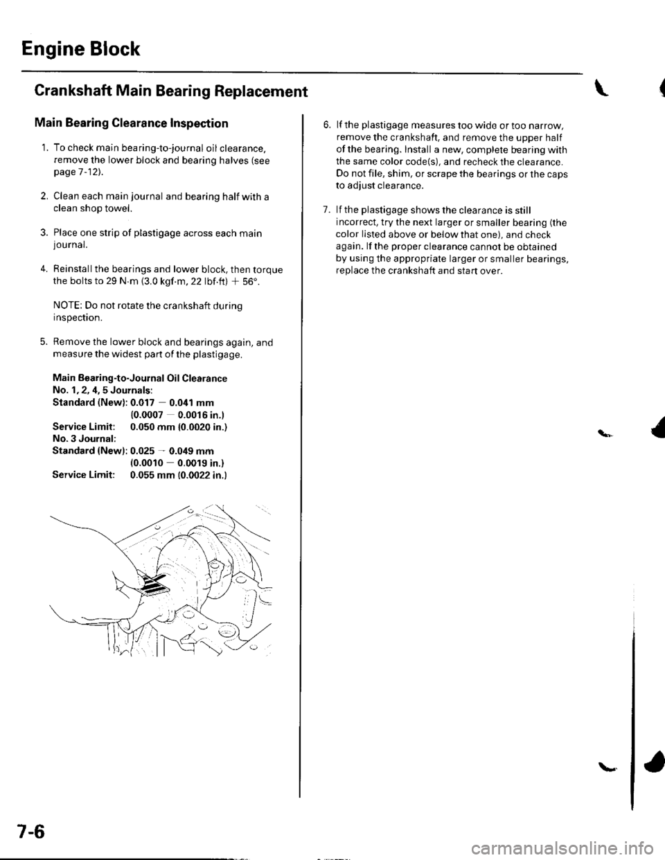
1. To check main bea ring-to-jou rna I oil clearance.
remove the lower block and bearing halves (see
page 1 -12)..
2, Clean each main journal and bearing half witha
clean shop towel.
3. Place one strip of plastigage across each main
lou rnal.
4. Reinstallthe bearings and lower block, then torque
the bolts to 29 N.m {3.0 kgf.m,22 lbf.ft) + 56'.
NOTE: Do not rotate the crankshaft during
Inspeclton.
5. Remove the lower block and bearings again, and
measure the widest part of the plastigage.
Main Bearing-to-Journal Oil Clearance
No. 1,2, 4,5 Journals:
Standard (New): 0.017 0.041 mm
Service Limit:
No.3 Journal:
10.0007 0.0016 in.l
0.050 mm {0.0020 in.)
Standard {Newl: 0.025 - 0.049 mm(0.0010 0.0019 in.)
Service Limit: 0.055 mm (0.0022 in.l
7-6
\.
6. lf the plastigage measures too wide or too narrow,
remove the crankshaft. and remove the upper half
ofthe bearing. Install a new, complete bearing with
the same color code{s), and recheck the clearance.
Do not file, shim, or scrape the bearings or the caps
to adjust clearance.
7. lf the plastigage shows the clearance is still
incorrect, try the next larger or smaller bearing (the
color listed above or below that one), and check
again. lf the proper clearance cannot be obtained
by using the appropriate larger or smaller bearings,
replace the crankshaft and start over.
Page 156 of 1139
Engine Block
Piston, Pin, and Connecting Rod Replacement
Disassembly
1. Remove the piston from the cylinder block (see
page 7 -12).
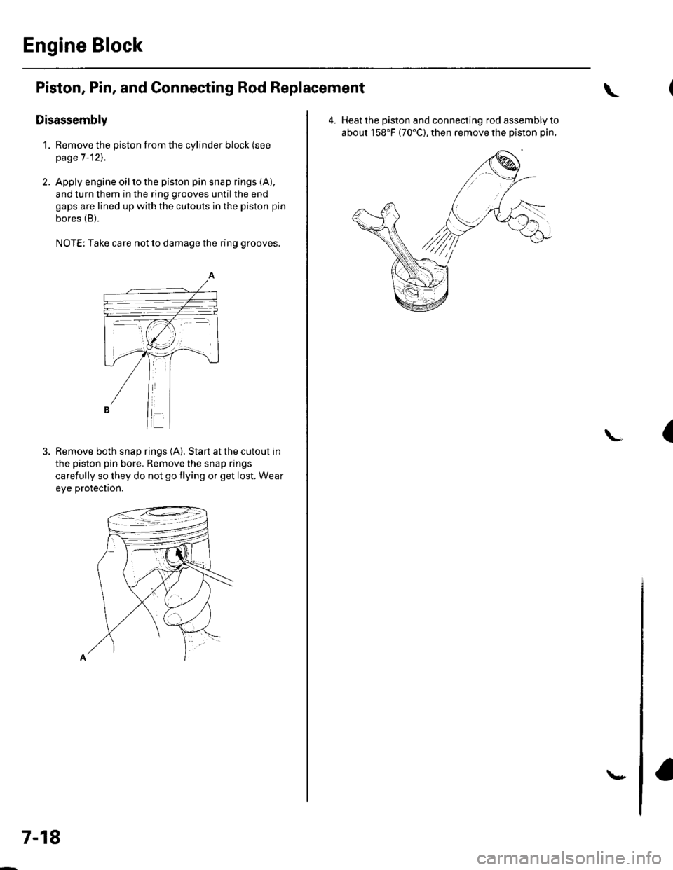
2. Apply engine oilto the piston pin snap rings (A),
and turn them in the ring grooves until the end
gaps are lined up with the cutouts in the piston pin
bores (B).
NOTE; Take care not to damage the ring grooves.
Remove both snap rings (A). Start at the cutout in
the piston pin bore. Remove the snap rings
carefully so they do not go flying or get lost. Wear
eve protection.
7-18
\"
4.Heat the piston and connecting rod assembly to
about 158'F (70"C), then remove the piston pin.
(\