radiator replace HONDA CIVIC 2003 7.G Owner's Guide
[x] Cancel search | Manufacturer: HONDA, Model Year: 2003, Model line: CIVIC, Model: HONDA CIVIC 2003 7.GPages: 1139, PDF Size: 28.19 MB
Page 337 of 1139
ldle Control System
DTC Troubleshooting
DTC P0505: ldle Control System Malfunction
NOTE: lf DTC P1519 is stored atthe same time as DTC
P0505, troubleshoot DTC P1519 first, then recheck for
DTC P0505.
1. Start the engine. Hold the engine at 3,000 rpm with
no load (in neutral) until the radiator fan comes on,
then let it idle,
2. Checkthe engine speed at idle with no,load
conditions: headlights, blower fan, rear defogger,
radiator fan, and air conditioner off.
Is the engine running at 750t50 rpm?
YES - Intermittent failure, system is OK at this
trme.I
NO lf the idle speed is less than 700 rpm, go to
step 3; if it's 800 rpm or higher, go to step 4.
3. Disconnect the idle air control {lAC) valve3P
connector.
Does the engine speed increase or fluctuate?
YES- Check the idle speed {see page 1 1-138). lf the
idle will not adjust properly, clean the passage in
the throttle body, and then adjust the idle. I
NO- Replace the IAC valve.I
4. Turn the ignition switch OFF.
5. Remove the intake air duct from the throttle body.
6. Start the engine, and let it idle.
11-130
(
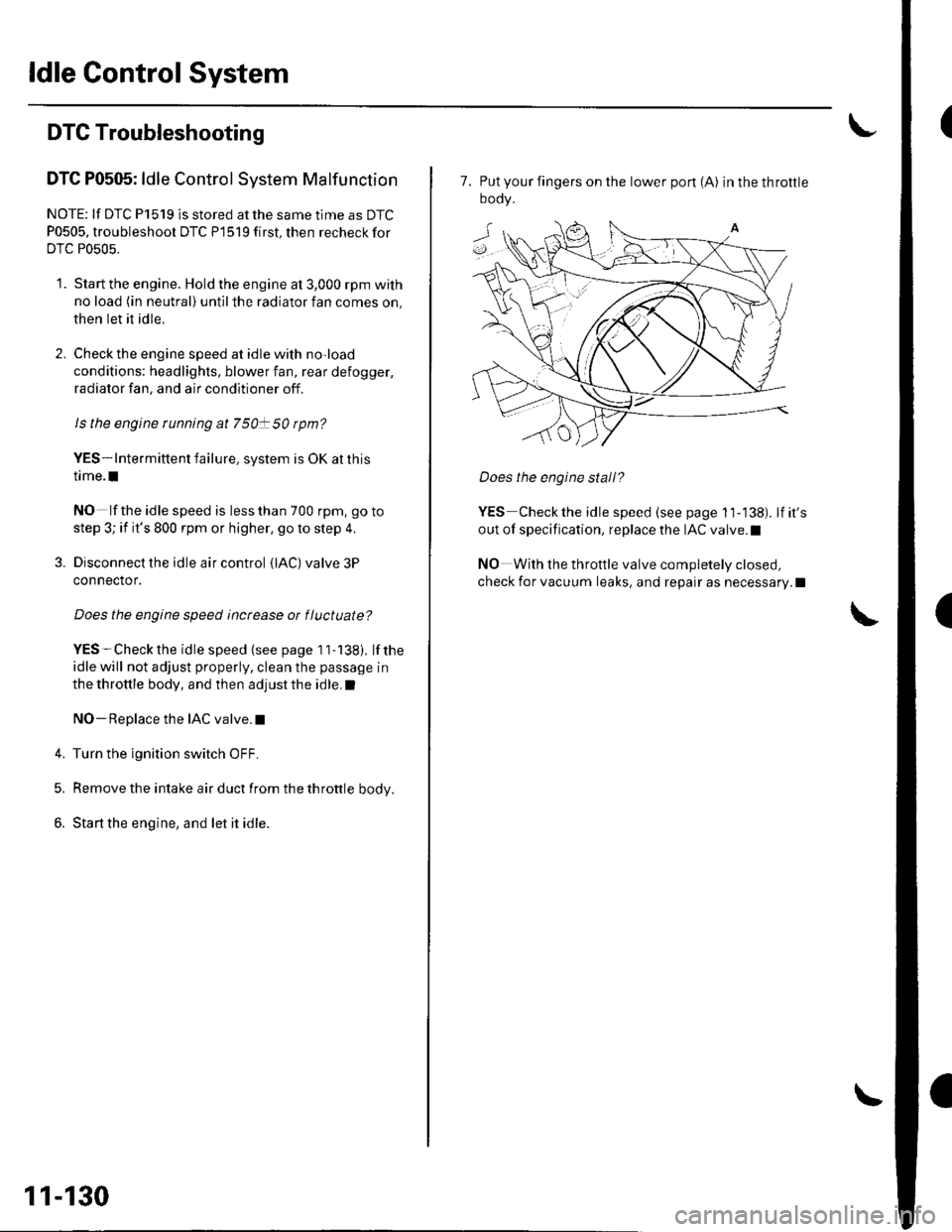
7. Put your fingers on the lower pon (A) inthethrottle
oooy.
Does the engine stall?
YES Checkthe idle speed (see page 11-138). lfit's
out of specification, replace the IAC valve.l
NO With the throttle valve completely closed,
check for vacuum leaks, and repair as necessary.l
Page 346 of 1139
ECM ldle Learn Procedure
The idle learn procedure must be done so the ECM can
learn the engine idle characteristics.
Do the idle learn procedure whenever you do any of
these actions:. Disconnect the battery.
Replace the ECM or disconnect its connector.
Reset the ECM.
NOTE: Erasing DTCS with the Honda PGM Tester
does not require you to do the idle learn procedure.
Remove the No.6 ECU {ECM) ( 15A) fuse from the
under-hood fuse/relay box.
Remove the No.19 baftery (80A) fuse from the under-
hood fuse/relay box.
Remove PGM-FI main relay 1.
Remove any of the wires from the under-hood fuse/
retay Dox.
Disconnect any of the connectors from the under
hood fuse/relay box.
Disconnect the connector between the engine
compartment wire harness and ECM wire harness.
Disconnect the G2 terminal from the transmission
ho u srng.
Disconnectthe G'l terminal from the body.
Disconnectthe G101 terminal from the cylinder head
cover.
Procedure:
To complete the idle learn procedure, do this:
1. Make sure all electrical items (Ay'C, audio, rear
defogger, l:ghts, etc.,) are off.
2. Start the engine, and hold it at 3,000 rpm with no
load {in neutral) until the radiator fan comes on, or
until the engine coolanttemperature reaches 194"F(90'c).
3. Let the engine idle for about 5 minutes with the
throttle fully closed.
NOTE: lf the radiator fan comes on, do not include its
running time in the 5 minutes.
11-139
Page 374 of 1139
Catalytic Converter System
DTC Troubleshooting
DTC P0420: Catalytic System Efficiency
Below Threshold
NOTE: lf some of the DTCS listed below are stored at
the same time as DTC P0420, troubleshoot those DTCS
first, then recheck for DTC P0420.
P0137, P0138: Secondary Heated Oxygen Sensor(secondary HO2S) (Sensor 2)
P0141: Secondary HO2S (Sensor 2) heater
1. Reset the ECM {see page 1'l-4}, then continue to
step 2 through 5 to reset the readiness code.
2. Start the engine. Hold the engine at 3,000 rpm with
no load (in neutral) untilthe radiator fan comes on.
Drive for about l0 minutes without stopping. Your
speeo can vary.
With the transmission in 4th gear, drive at a steady
speed between 50 62 mph (80-'100 km/h) for
30 seconds.
Repeat step 4 three times. Between each repetition,
close the throttle completely for 1 2 seconds. lf
the engine is stopped during this part of the
procedure, repeat steps 3, 4 and 5.
Check for a Temporary DTC with the scan tool.
Does the scan tool indicate Temporaty DTC
P0420?
YES Check the TWC. lf necessary, replace the
TWC.I
NO Check for readiness code completion. lfthe
readiness is complete, it was a interminent failure,
and the system is OK at this time. lf the readiness
code is incomplete, repeat steps 2 through 5.1
4.
11-167
Page 773 of 1139
21-2
z t-'5
z t-o
z t-o
21-8
21-9
21-10
21-11
21-14
z t- to
HVAC (Heating, Ventilation, and Air Gonditioningl
Heating and Air Conditioning
SpecialTools
Comoonent Location lndex ........
A/C Service Tios and
Precautions
A,/C Refrigerant Oil
ReDlacement
General Troubleshooting
lnformation
DTC Troubleshooting Index .......
Symptom Troubleshooting
1ndex..............
System Description .....................
Circuit Diagram
DTC Troubleshooting ..................
Recirculation Control Motor
CircuitTroubleshooting .......... 21-25
Heater Control Power and Ground
Circuits Troubleshooting ........ 21-27
Condenser Fan Circuit
Troubleshooting ...................... 21-28
Radiator and Condenser Fans
Common Circuit
Troubfeshooting ...................... 21-29
Compressor Clutch Circuit
Troubleshooting ...................... 21-30
A,/C Pressure Switch Circuit
Troubleshooting ...................... 21-32
Air Mix Control Motor
Test and Reolacement ............. 21-34
Mode Control Motor
Test and Replacement ............. 21-35
Recirculation Control Motor
Test and Reolacement ............. 21-36
Evaporator Temperature Sensor
Reolacement and Test ............. 21-31
Power Transistor Test ................. 21 -38
Heater Control Panel and
Push Switch Assemblv
Removal and Installation ........ 21-38
Dust and Pollen Filter
Reolacement ..21-39
Blower Unit Removal and
lnstallation ...... 21-39
Blower Unit Comoonents
ReDlacement ............................ 21-41
Evaporator Core
Reolacement ..21-42*Heater Unit/Core
ReDlacement ..21-43
Heater Valve Cable
Adjustment .....21-46
CompressorReplacement .......... 21-47
Comoressor Clutch Check .......... 21-48
Comoressor Clutch Overhaul ..... 21-49
Compressor Thermal Protector
Reo1acement ............................ 21-51
Comoressor Relief Valve
Reolacement ............................ 21-51
Condenser Reolacement ............ 21-52
Refrigerant Recovery .................. 21-53
System Evacuation ...................... 21-54
System CharginS ......................... 21-55
Refrigerant LeakTest .................. 21-56
A,/C Svstem Tests ........................ 21-57
Page 799 of 1139
Heating and Air Conditioning
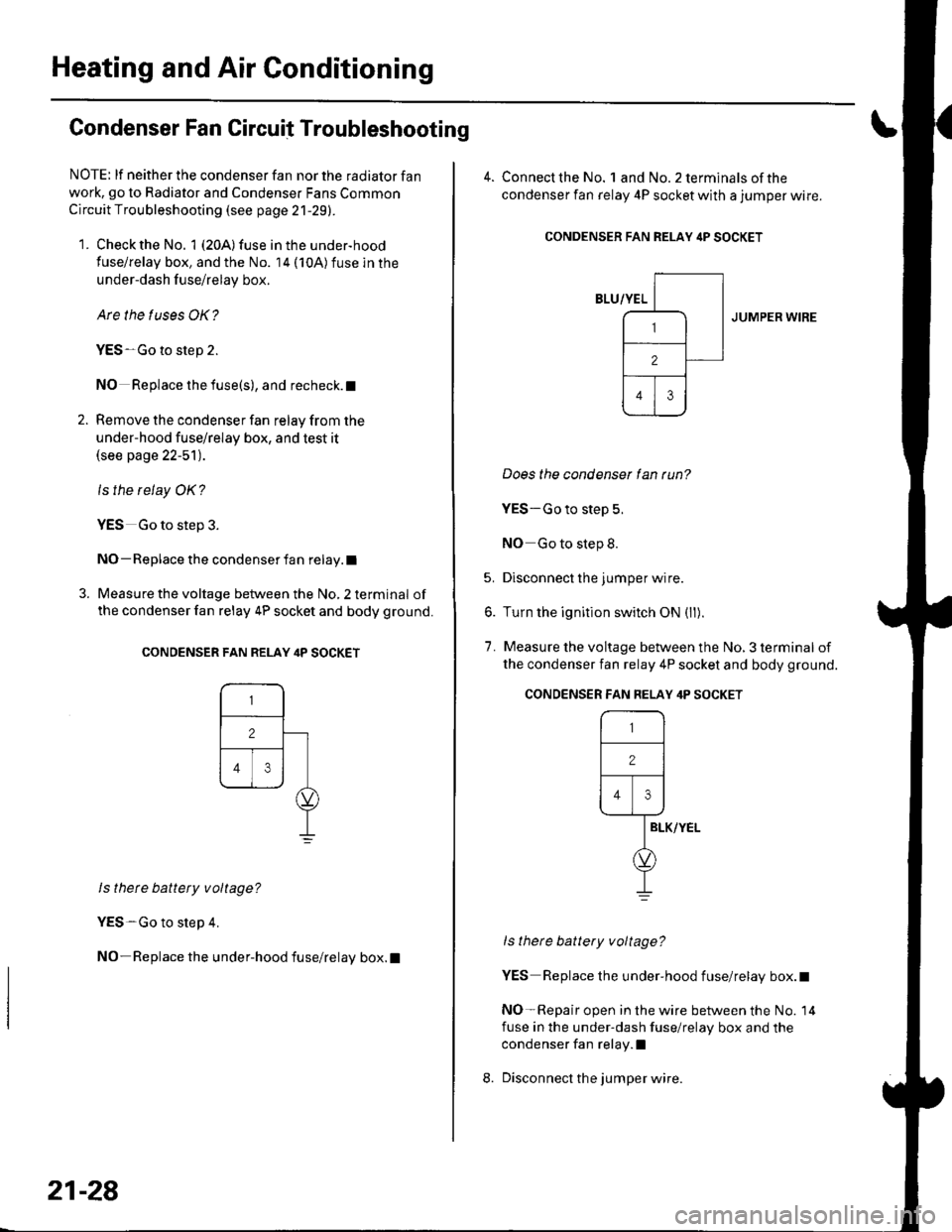
Condenser Fan Circuit Troubleshooting
NOTE: lf neither the condenser fan nor the radiator fan
work, go to Radiator and Condenser Fans Common
Circuit Troubleshooting (see page 21-29).
1. Check the No. 1 (20A) fuse in the under-hood
fuse/relay box, and the No. 14 (10A)fuse in the
under-dash f use/relay box.
Are the tuses OK?
YES-Go to step 2.
NO Replace the fuse(s), and recheck. t
2. Remove the condenser fan relay from the
under-hood fuse/relay box, and test it(see page 22-51).
ls the relay OK?
YES Go to step 3.
NO- Replace the condenser fan relay.l
3. Measure the voltage between the No, 2 terminal of
the condenser fan relay 4P socket and body ground.
CONDENSER FAN RELAY ilP SOCKET
ls thete battery voltage?
YES-Go to step 4.
NO-Replace the under-hood fuse/relay box.l
21-28
4. Connect the No. landNo.2terminalsof the
condenser fan relay 4P socket with a jumper wire.
CONDENSER FAN RELAY itP SOCKET
JUMPER WIRE
Does the condenser lan tun?
YES-Go to step 5.
NO Go to step 8.
5. Disconnect the jumper wire.
6. Turn the ignition switch ON (ll).
7. Measure the voltage between the No, 3 terminal of
the condenser fan relay 4P socket and body ground.
ls there battery voltage?
YES Replace the under-hood fuse/relay box.t
NO-Repair open in the wire between the No. 14
fuse in the under-dash fuse/relay box and the
condenser fan relay.l
Disconnect the jumper wire.
CONDENSER FAN FELAY 4P SOCKET
r-,_-l
12 |
Flr\----1--rl
IELK/YEL
d,
I
Page 800 of 1139
9.
10.
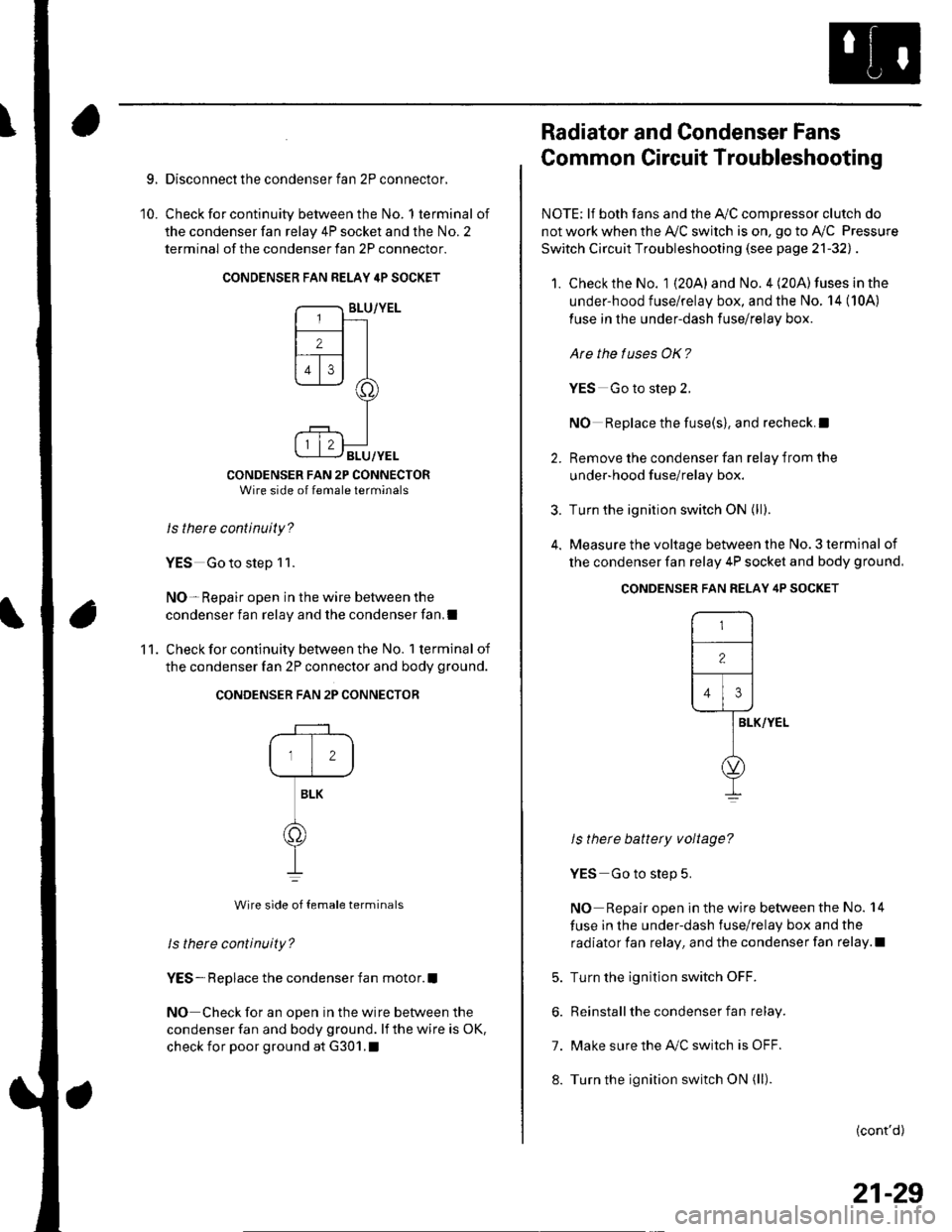
Disconnect the condenser fan 2P connector,
Check for continuity between the No. 1 terminal of
the condenser fan relay 4P socket and the No. 2
terminal of the condenser fan 2P connector.
CONDENSER FAN RELAY 4P SOCKET
CONDENSER FAN 2P CONNECTORWire side of female terminals
Is there continuity?
YES Go to step 1 1.
NO- Repair open in the wire between the
condenser fan relay and the condenser fan,I
Check for continuity between the No. 1 terminal of
the condenser fan 2P connector and body ground.
CONDENSER FAN 2P CONNECTOR
12
BLK
o
Wire side of {emale terminals
ls there continuity?
YES- Replace the condenser fan motor.I
NO Check for an open in the wire between the
condenser fan and body ground. lf the wire is oK,
check for poor ground at G301.1
'11 .
Radiator and Condenser Fans
Common Circuit Troubleshooting
NOTE; lf both fans and the Ay'C compressor clutch do
not work when the Ay'C switch is on, go to Ay'C Pressure
Switch Circuit Troubleshooting (see page 21-32l, .
1. Check the No. 1 {20A} and No. 4 (20A) fuses in the
under-hood fuse/relay box, and the No. 14 (10A)
fuse in the under-dash fuse/relay box.
Are the tuses OK?
YES Go to steD 2.
NO Replace the fuse(s), and recheck.l
2. Remove the condenser fan relav from the
under-hood f use/relay box.
3. Turn the ignition switch ON (ll;.
4. Measure the voltage between the No. 3 terminal of
the condenser fan relay 4P socket and body ground.
ls there battery voltage?
YES Go to step 5.
NO Repair open in the wire between the No. 14
fuse in the under-dash fuse/relay box and the
radiator fan relay, and the condenser fan relay.l
5. Turn the ignition switch OFF.
6. Reinstall the condenser fan relay.
7. Make sure the IVC switch is OFF.
8. Turn the ignition switch ON (ll).
(cont'd)
CONDENSER FAN RELAY 4P SOCKET
r-,
-l
12lf---r---
l,l,l
lar-vver-
l
o
I
21-29
Page 801 of 1139
Heating and Air Conditioning
Radiator and Condenser Fans
Common
(cont'dl
Circuit Troubleshooting
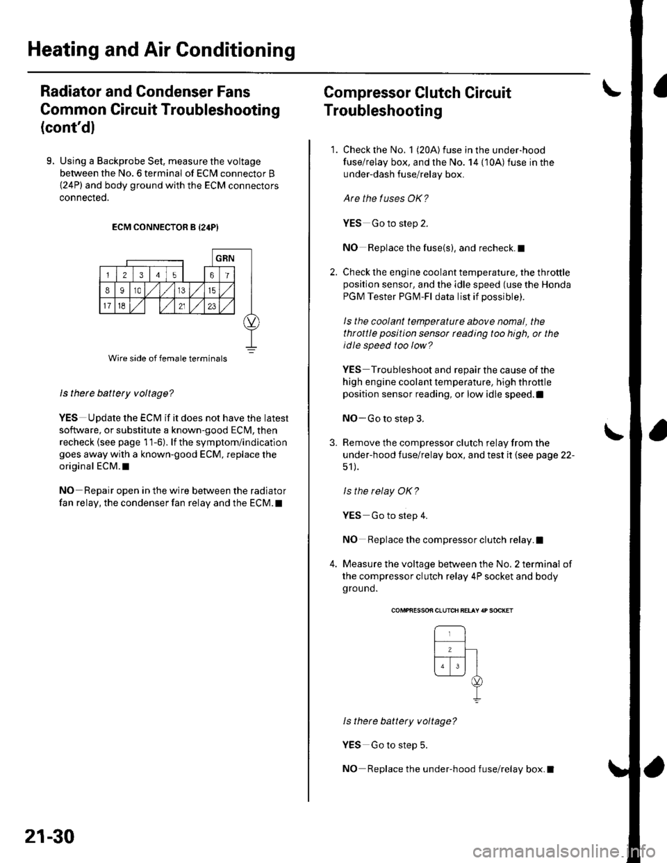
9. Using a Backprobe Set, measure the voltage
between the No. 6 terminal of ECN4 connector B
{24P) and body ground with the ECM connectors
connecteo.
ECM CONNECTOR B {24P}
ls there battery voltage?
YES UDdate the ECM if it does not have the latest
so{tware, or substitute a known-good ECM, then
recheck (see page 11-6). lf the symptom/indication
goes away with a known-good ECM, replace the
original ECM.I
NO Repair open in the wire between the radiator
fan relay, the condenser fan relay and the ECM. t
Wire side of female terminals
21-30
Compressor Clutch Circuit
Troubleshooting
1. Check the No. 1 (20A) fuse in the under-hood
fuse/relay box, and the No. 14 {10A)fuse in the
under-dash fuse/relay box.
Are the tuses OK?
YES Go to step 2.
NO Replace the fuse(s), and recheck.I
2. Check the engine coolant temperature, the throttleposition sensor, and the idle speed (use the Honda
PGM Tester PGM-Fl data list if possible).
ls the coolant temperaturc above nomal, the
throttle position sensor rcading too high, or the
idle speed too low?
YES Troubleshoot and repair the cause of the
high engine coolant temperature, high throttle
position sensor reading, or low idle speed.l
NO-Go to step 3.
3. Remove the compressor clutch relay from the
under-hood fuse/relay box, and test it (see page 22-
51 ).
ls the relay OK?
YES Go to step 4.
NO Replace the compressor clutch relay.I
4. Measure the voltage between the No. 2 terminal of
the compressor clutch relay 4P socket and body
ground.
\
COMPfiESSON CLUTCH BELAY 'P SOCKET
ls there battery voltage?
YES Go to step 5.
NO Replace the under-hood fuse/relay box.I
Page 814 of 1139
Heater Unit/Core Replacement
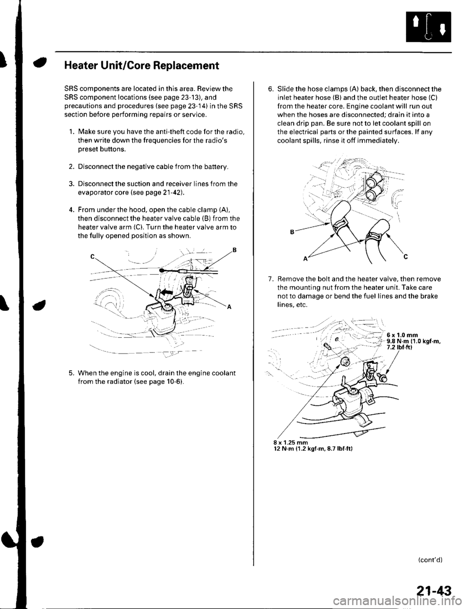
SRS components are located in this area. Review the
SRS component locations (see page 23'13), and
precautions and procedures (see page 23-14) in the SRS
section before performing repairs or service.
1. Make sure you have the anti-theft code forthe radio,
then write down the freouencies for the radio's
Dreset buttons.
4.
Disconnect the negative cable from the battery,
Disconnect the suction and receiver lines from the
evaporator core (see page 21-42).
From under the hood, open the cable clamp (A),
then disconnect the heater valve cable (B) from the
heater valve arm (C). Turn the heater valve arm to
the fully opened position as shown
When the engine is cool, drain the engine coolant
from the radiator (see page 10-6).
6. Slide the hose clamps (A) back, the n d isconnect the
inlet heater hose (B) and the outlet heater hose (C)
from the heater core. Engine coolant will run out
when the hoses are disconnected; drain it into a
clean drip pan. Be sure not to let coolant spill on
the electrical parts or the painted surfaces. lf any
coolant spills, rinse it off immediately.
Remove the bolt and the heater valve, then remove
the mounting nut from the heater unit. Take care
not to damage or bend the fuel lines and the brake
lines, etc.
7.
8 x 1.25 mm12 N.m (1.2 kgf.m,8.7lbf.ft)
(cont'd)
21-43
Page 823 of 1139
Heating and Air Conditioning
Gondenser Replacement
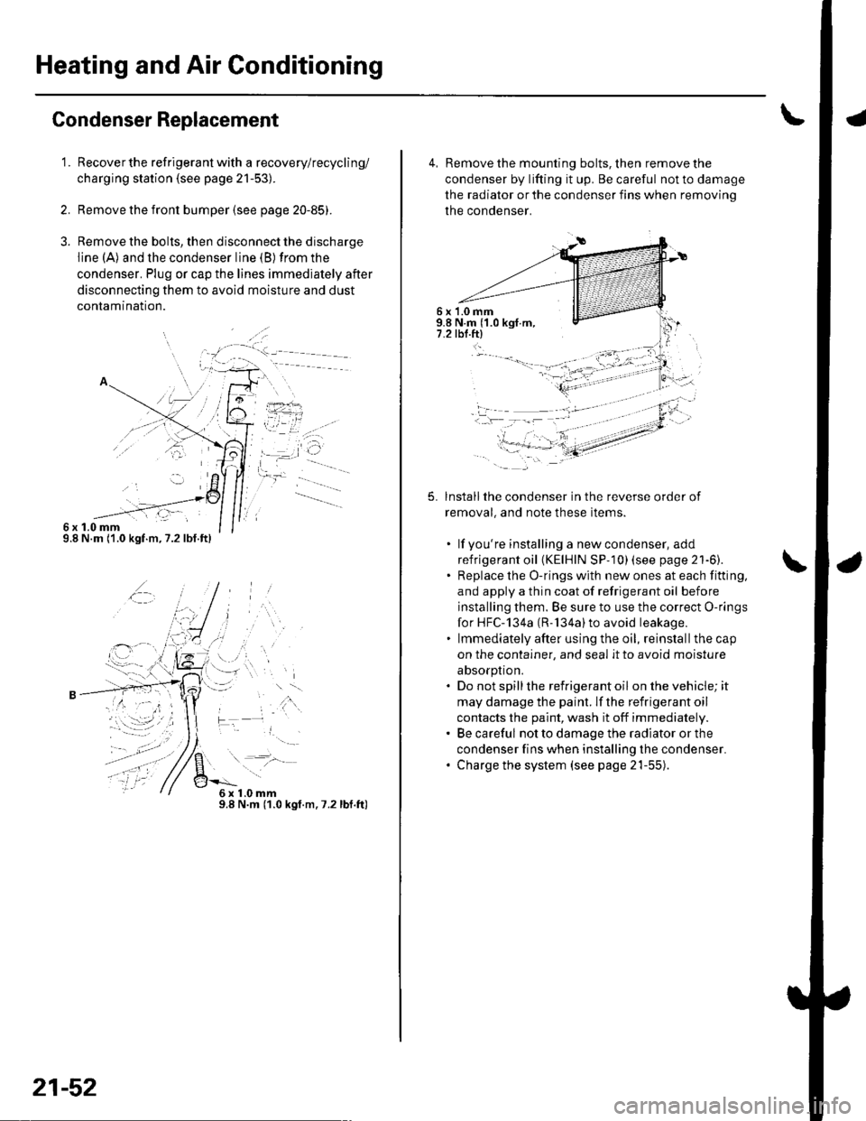
1.
6x1.0mm9.8 N.m ('1.0 kgf.m,7.2lbf.ft)
Recover the refrigerant with a recovery/recycling/
charging station (see page 21-53).
Remove the front bumper {see page 20-85).
Remove the bolts, then disconnect the discharge
line (A) and the condenser line (B) from the
condenser. Plug or cap the lines immediately after
disconnecting them to avoid moisture and dust
conlamtnaflon.
,t\
6x1.0mm9.8 N.m (1.0 kgt.m.7.2lbf.ft)
21-52
4, Remove the mounting bolts, then remove the
condenser by lifting it up. Be careful not to damage
the radiator or the condenser fins when removino
the condenser.
6 x '1.0 mm9.8 N.m ('1.0 kgf.m,7.2 tbl.ftl
5.lnstallthe condenser in the reverse order of
removal, and note these items.
. lf you're installing a newcondenser, add
refrigerant oil (KElHlN SP- 10) lsee page 21'6).. Replace the O-rings with new ones at each fitting,
and apply a thin coat of refrigerant oil before
installing them. Be sure to use the correct O-rings
for HFC-134a (R-'134a)to avoid leakage.. lmmediately after using the oil, reinstallthe cap
on the container, and seal it to avoid moisture
absorption.. Do not spillthe refrigerant oil onthevehicle;it
may damage the paint. lf the refrigerant oil
contacts the paint, wash it off immediately.. Be careful not to damage the radiator or the
condenser fins when installing the condenser.. Charge the system (see page 21-55).
t -"'.
f,
t-
-li .:)-:.-- ---- - -'
Page 828 of 1139
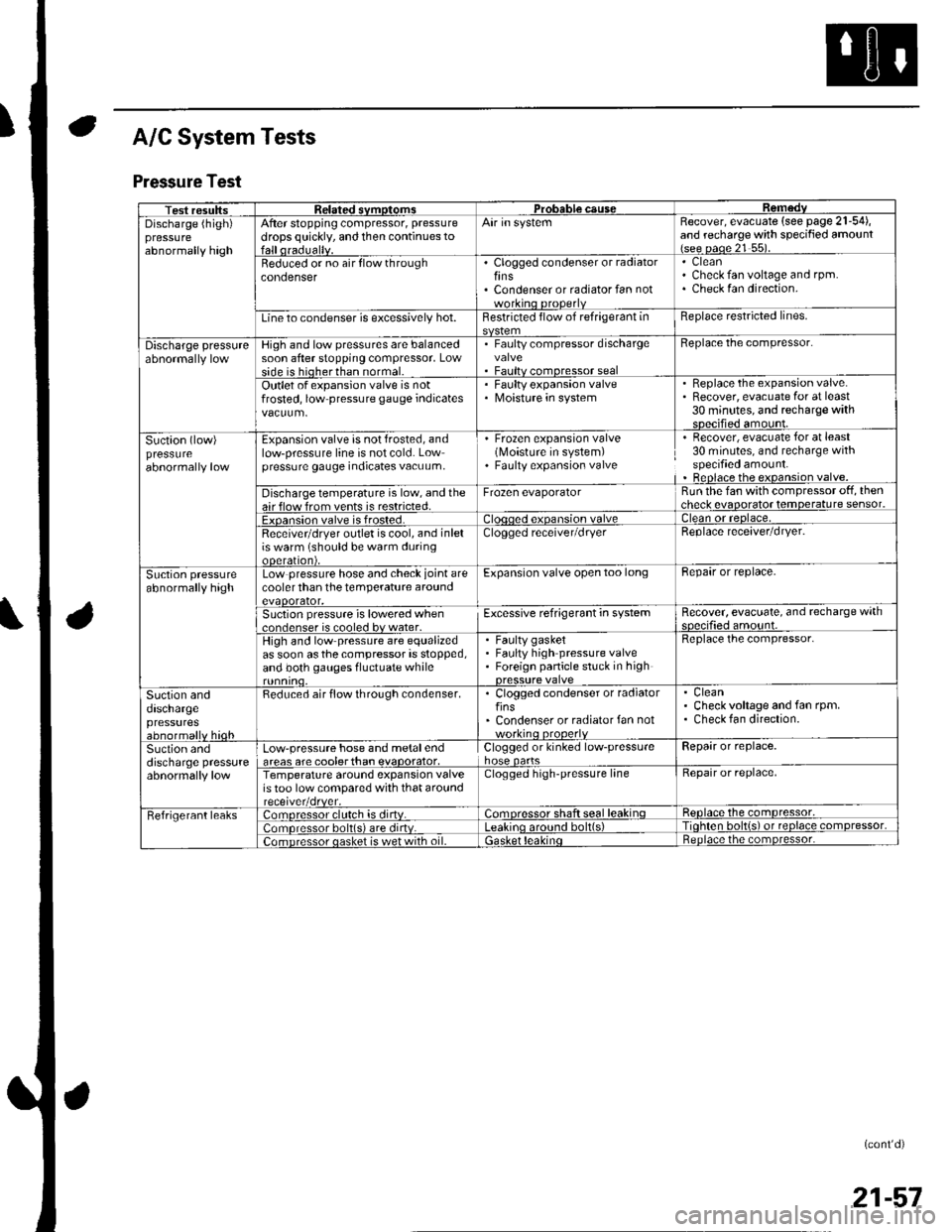
A/C System Tests
Pressure Test
Test resultssvmotom3DGaUSeDischarge (high)pressureabnormally high
After stopping compressor, pressure
drops quickly, and then continues toAir in systemRecover, evacuate (see page 21-54),and recharge with specified amount{see oaoe 21 55).
Beduced or no air flow throughcondenserClogged condenser or radiatorfinsCondenser or radiator fan not
CleanCheck fan voltage and rpm.Check fan direction.
Line to condenser is excessively hot.Restricted flow of refrigerant inReplace restricted lines.
Discharge pressureHigh and low pressures are balancedsoon after stopping compressor, Lowside is hioherthan normal.
. Faulty compressor dischargevalve. Faultv comoressor seal
Beplace the compressor.
Outlet of expansion valve is notfrosted, low pressure gauge indicatesFaulty expansion valveMoisture in system
. Replace the expansion valve.. Recover, evacuate for at least30 minutes, and recharge withsDecified amount.
Suction (low)pressureabnormally low
Expansion valve is not frosted, andlow-pressure line is not cold. Lowpressure gauge indicates vacuum,
' Frozen expansion valve(Moisture in system). Faulty expansion valve
Recover, evacuate for at least30 minutes, and recharge withspecified amount.Beplace the expansion valve.
Discharge temperature is low, and theair flow from vents is restricted.Frozen evaporatorRun the fan with compressor off, thencheck evaooratot temoerature sensor.
Exoansion valve is frosted.ean or reolace,
Receivetdryer outlet is cool, and inletis warm (should be warm duringooeralton),
Clogged receiver/dryerReplace receaver/dryer.
Suction pressureabnormally highLow pressure hose and check joint arecooler than the temperature aroundevaoorator,
Expansion valve open too longBepair or replace.
Suction pressure is lowered when..nrlenser is cooled bv water.Excessive refrigerant in systemRecover, evacuate, and recharge withqnp.ifie.lamo'rnr
High and low pressure are equalizedas soon asthecompressor is stopped,and both gauges fluctuate while
Faulty gasketFaulty high pressure valveForeign panicle stuck in high
Replace the compressor.
Suction anddaschargepressuresabnormallv hioh
Reduced air flow through condenser.. Clogged condenser or radiatorfins' Condenser or radiator fan notworkino orooerlv
CleanCheck voltage and fan rpm.Check fan direction.
Suction anddischarge pressureabnormally low
Low-pressure hose and metalendareas are coolerthan evaoorator,Clogged or kinked low-pressurehose oartsRepair or replace.
Temperature around expansion valveis too low compared with that aroundClogged high-pressure lineRepair or replace,
Fefrigerant leaks:omoressor clulch is dirtv.:omoressor shaft seal leakinqReolace the comDressor,
lomoressor bolt(s) are dirtv.no around bolt(s)Tiohten bolt{s) ot reolace comDressor,
;omDressor oasket is wet with oil.ietnoace the comoressor.
(cont'd)
21-57