ect HONDA CIVIC 2003 7.G Workshop Manual
[x] Cancel search | Manufacturer: HONDA, Model Year: 2003, Model line: CIVIC, Model: HONDA CIVIC 2003 7.GPages: 1139, PDF Size: 28.19 MB
Page 639 of 1139
\
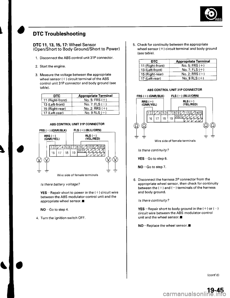
DTC Troubleshooting
DTC 11, 13, 15, 17: Wheel Sensor
(Open/Short to Body Ground/Short to Power)
1. Disconnect the ABS control unit 31P connector.
2. Sta rt the engine.
3. Measure the voltage between the appropriate
wheel sensor (*)circuitterminal of theABS
control unit 31P connector and body ground (see
table).
DTCADpropriate Terminal
11 (Rioht-front)No.5: FRS (t)
13 (Left-front)No, 7: FLS (*)
15 {Riqht-rear}No. 2: RRS (*)
17 (Left-rear)No.9 RtS (f )
ABS CONTROL UNIT 31P CONNECTOR
FRS {+IIGNR/BLK} FLS I+I (BLU
RRS {+)(GNR/YEL)
Wire side of female terminals
ls thete battery voltage?
YES Repair short to power in the (+) circuit wire
between the ABS modulator-control unit and the
appropriate wheel sensor. I
NO Go to step 4.
4. Turn the ignition switch OFF.
5. Check for continuity between the appropriate
wheel sensor (+ ) circuit terminal and body ground
{see table).
DTCAppropriate Terminal
11 (Riqht-front)No. 5: FRS (+)
13 (Left-front)No. 7: FLS (*)
15 (Rioht-rear)No.2: RRS (*)
17 (Left-rear)No.9 RLS (+l
ABS CONTROL UNIT 31P CONNECTOR
Wire side
ls there continuity?
YES Go to step 6.
NO-Go to step 7.
Disconnect the harness 2P connector from the
appropriate wheel sensor, then check for continuity
between the 1+)and ( )terminals ofthe harness
and body ground.
ls there continuity?
YES-Repair shortto body ground in the (+)or { )
circuit wire between the ABS modulator-control
unit and the wheel sensor.l
NO Repiace the wheel sensor.l
(cont'd)
Wire side of female terminals
19-45
Page 640 of 1139
ABS Components
DTC Troubleshooting (cont'dl
7. Check the resistance between the appropriate
wheel sensor (+) and ( ) circuit terminals {seeta ble).
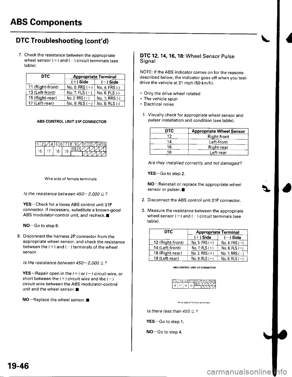
DTCAppropriate Terminal
l+) Side*lSide
11 {Riqht-front)No.5: FRS (*)No.4:FRS 1-)'13 {Left-front)No. 7: FLS {+iNo.6: FLS (-
15 (Rioht-rear)No. 2: RBS {+)No. 1:RBS (-)
17 (Left-rear)No.9: RLS 1-No.8: BLS (-
ABS CONTROL UNIT 31P CONNECTOR
Wire side of female terminals
Is the rcsistance between 450 2,000 A ?
YES Check for a loose ABS control unit3lP
connector. lf necessary. substitute a known-good
ABS modulator-control unit, and recheck.l
NO Go to step 8.
Disconnect the harness 2P connector from theappropriate wheel sensor, and check the resistance
between the (+) and { )terminalsof thewheel
sensor.
ls the resistance between 450- 2,000 Q ?
YES-Repair open in the (+) or (-) circuit wire, orshort between the (+) circuit wire and the { )circuit wire between the ABS modulator-control
unit and the wheel sensor.l
NO Replace the wheel sensor.l
19-46
DTC12,14, 16, 18: Wheel Sensor Putse
Signal
NOTE: lf the ABS indicator comes on for the reasonsdescribed below, the indicator goes off when you test-drive the vehicle at 31 mph (50 km/nl.
. Only the drive wheel rotated. The vehicle spun. Electrical noise
1. Visually check for appropriate wheel sensorandpulser installation and condition (see table).
DTCAppropriate Wheel Sensor
12Riqht-front
14Left-front
Riqht-rear
18Left-rear
Ate they installed correctly and not damaged?
YES-Go to step 2,
NO Reinstall or replace the appropriate wheelsensor or pulser,I
Disconnect the ABS control unit 31P connector.
Measure the resistance between the appropriate
wheel sensor ( f) and ( ) circuit terminals (see
table).
ls therc less than 450 Q ?
YES Go to step 1.
NO-Go to step 4.
\\|D
2.
3.
DTCAppropriate Terminal
l*) Side) Side
12 {Rioht-front)No.5:FBS (*No.4:FBS
14 (Left-front)No.7;FLS l*No,6:FLS
16 (Riqht.rear)No.2: RRS (*No. 1:BRS
18 (Left-readNo.9: BLS 1-No.8:RLS
Page 641 of 1139
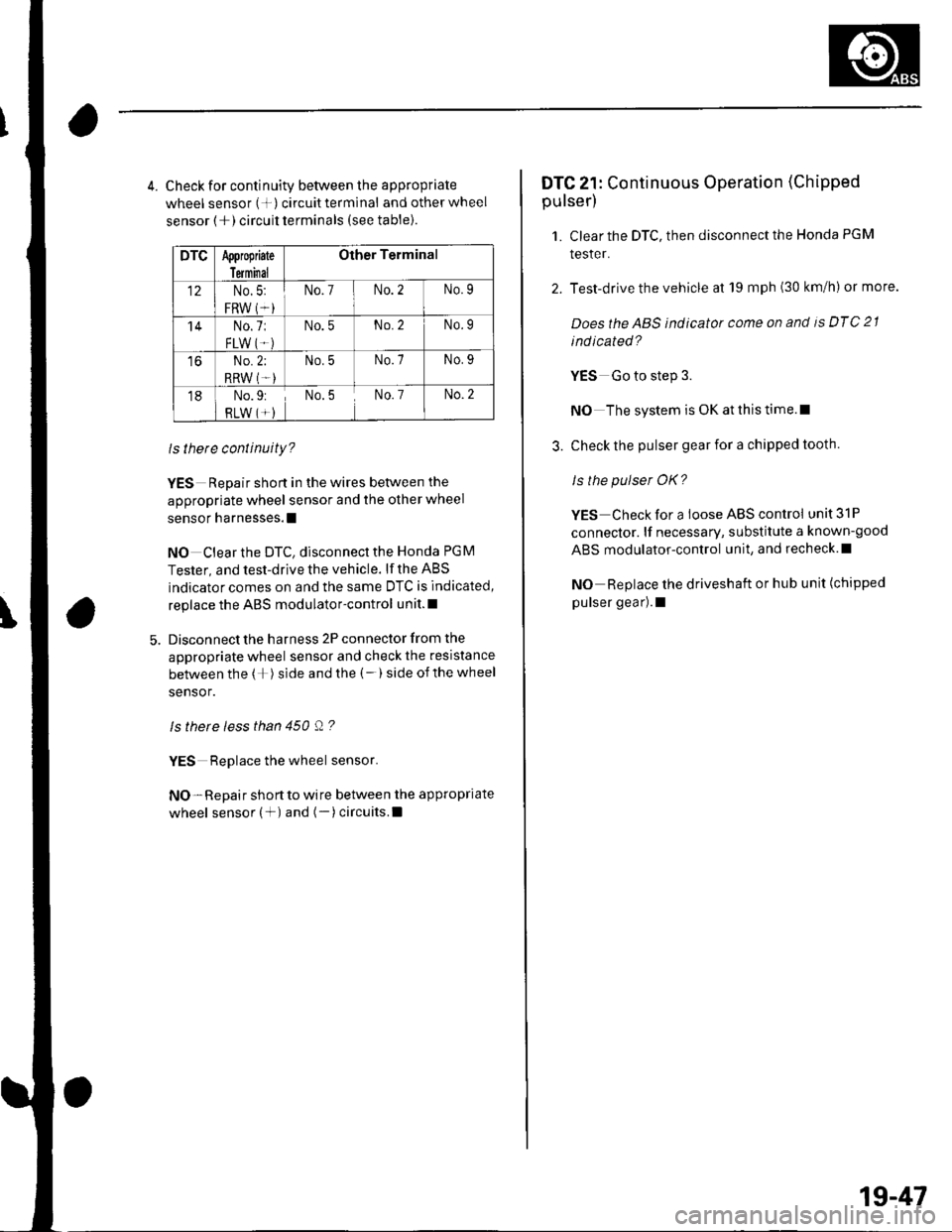
4. Check for continuity between the appropriate
wheel sensor (+) circuittermlnal and otherwheel
sensor (+) circuit terminals (see table).
DTCAppropiate
Terminal
Other Terminal
12No.5:
FRW (*i
No.7No.2No.9
'14No.7:
FLW IT.)
No.5No.2No.9
toNo.2;
RRW (T-)
No.5No.7No.9
18No.9:
RLW (*)No.5No. 7No.2
ls there continuity?
YES Repair short in the wires between the
appropriate wheel sensor and the other wheel
sensor harnesses.l
NO Clear the DTC, disconnect the Honda PGM
Tester, and test-drive the vehicle. lf the ABS
indicator comes on and the same DTC is indicated,
replace the ABS modulator-control unit.l
Disconnect the harness 2P connector from the
appropriate wheel sensor and check the resistance
between the (+) side and the (-) side ofthe wheel
sensor.
ls there less than 450 Q ?
YES Replace the wheel sensor.
NO- Repair short to wire between the appropriate
wheel sensor (+) and (-)circuits.l
DTC 21: Continuous Operation (Chipped
pulser)
1. Clear the DTC, then disconnect the Honda PGM
tesler.
2. Test-drive the vehicle at 19 mph (30 km/h) or more.
Doesthe ABS indicator come on and is DTC 21
ind icated?
YES Go to step 3.
NO The system is OK at this time.l
3. Check the pulser gear for a chipped tooth.
ls the pulser OK?
YES Check for a loose ABS control unit 31P
connector. lf necessary, substitute a known-good
ABS modulator-control unit, and recheck.l
NO Replace the driveshaft or hub unit (chipped
pulser gear).1
1g-47
Page 642 of 1139
ABS Components
DTC Troubleshooting (cont'd)
DTC 31, 32. 33, 34, 35, 36, 37, 38: Solenoid
1. Clear the DTC, then disconnect the Honda PGN4
Tester.
2. Test-drive the vehicle.
Does the ABS ind icator come on and are DT Cs 31,
32, 33, 34, 35, 36, 37, 38 indicated?
YES Replace the ABS modulator-control unit.t
NO The system is OK at this time. t
19-48
DTC 51: Motor Locked
'1. Check the No. 10 (40A)fuse in the under-hoodfuse/
retay Dox.
ls the tuse OK?
YES-Reinstall the fuse, and go to step 2.
NO- Replace the fuse, and recheck.l
2. Disconnect the ABS control unit 31P connector.
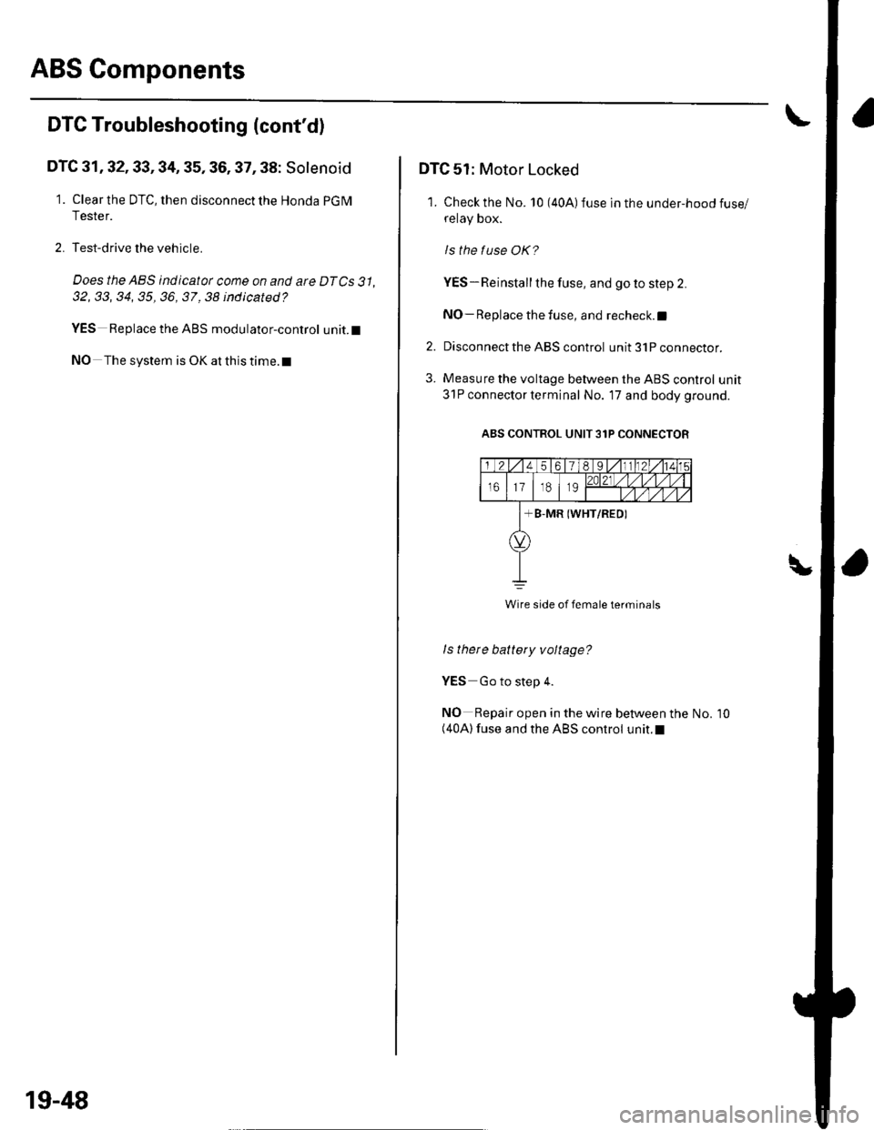
3. Measure the voltage between the ABS control unit
31P connector terminal No. 17 and body ground.
ABS CONTROL UNIT 31P CONNECTOR
I
Wire side of female terminals
ls thete battery voltage?
YES Go to step 4.
NO Repair open in the wire between the(40A) fuse and the ABS control unit.l
No. 10
Page 643 of 1139
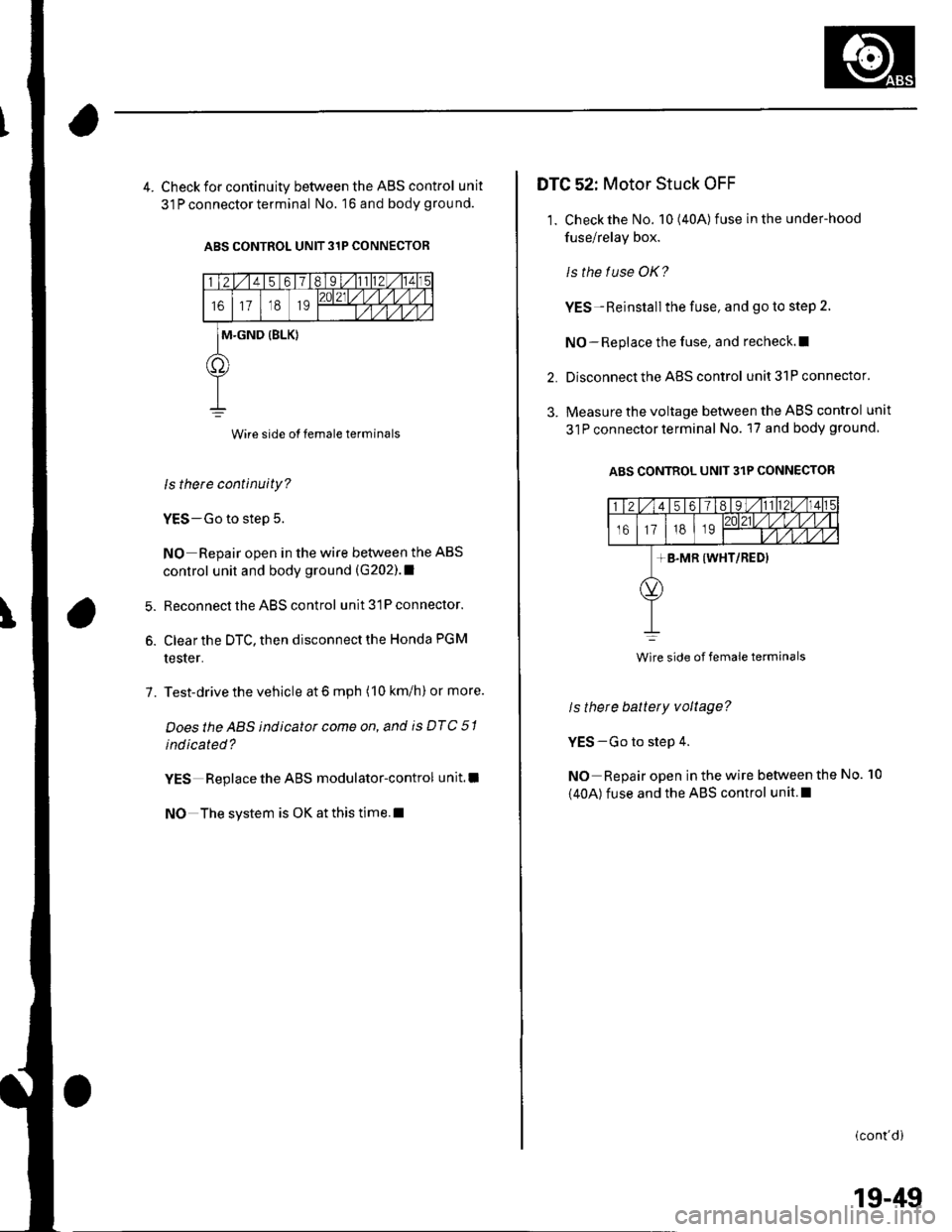
4. Check for continuity between the ABS control unit
31 P connector terminal No. 16 and body grou nd.
ABS CONTROL UNIT 31P CONNECTOR
Wire side of female terminals
ls there continuity?
YES-Go to step 5.
NO Repair open in the wire between the ABS
control unit and body ground (G202).1
Reconnect the ABS control unit 31P connector.
Clear the DTC, then disconnect the Honda PGM
tester.
Test-drive the vehicle at 6 mph (10 km/h) or more.
Doesthe ABS indicator come on, and is DTC 51
indicated?
YES Replace the ABS modulator-control unit.l
NO The system is OK at this time.l
6.
7.
DTG 52: Motor Stuck OFF
1. Check the No. 10(40A) fuse in the under-hood
fuse/relay box.
ls the f use OK?
YES-Reinstall the fuse, and go to step 2.
NO-Replace the fuse, and recheck.l|
Disconnect the ABS control unit 31P connector.
Measure the voltage between the ABS control unit
31P connector terminal No. 17 and body ground
ABS CONTROL UNIT 31P CONNECTOR
2.
3.
ls there battery voltage?
YES-Go to step 4.
NO Repair open in the wire between the
(40A) fuse and the ABS control unit.l
No. 10
(cont'di
Wire side of female terminals
19-49
Page 644 of 1139
ABS Components
DTC Troubleshooting (cont'dl
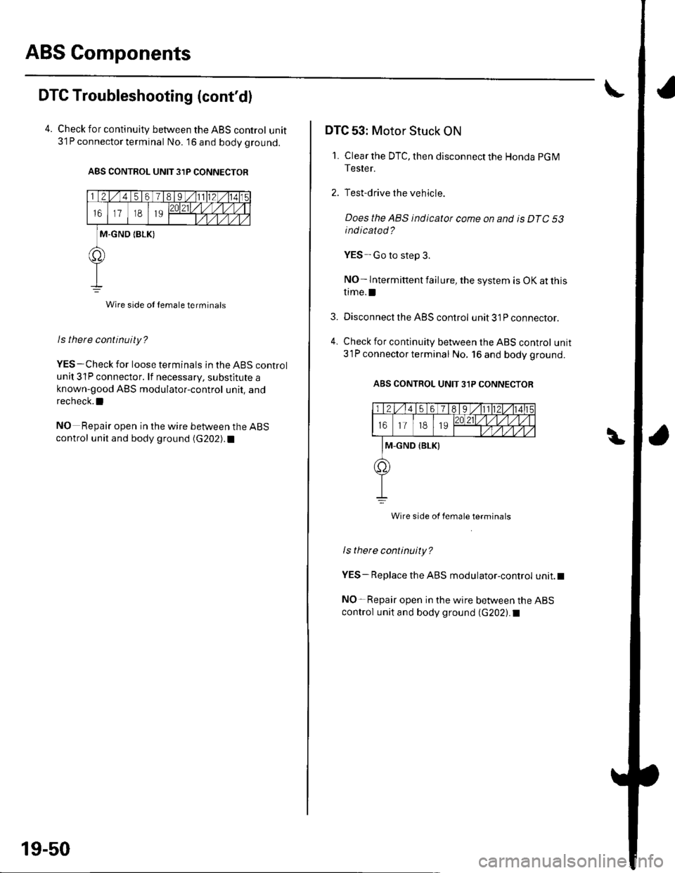
4. Check for continuitv between the ABS control unit31P connector terminal No. 16and bodyground.
ABS CONTROL UNIT 31P CONNECTOR
Wire side ol female terminals
ls there continuity?
YES-Check for loose terminals in the ABS control
unit 31P connector. lf necessary, substitute aknown-good ABS modulator-control unit, and
recheck.l
NO Repair open in the wire between the ABS
control unit and body ground (G202).1
19-50
3.
DTC 53: Motor Stuck ON
1. Clear the DTC, then disconnect the Honda pG M
Tester.
2. Test-drive the vehicle.
Does the ABS indicatot come on and is DTC 53
indicated?
YES -Go to step 3.
NO- lntermittent failure, the system is OK at this
trme.l
Disconnect the ABS control unit 31P connector.
Check for continuity between the ABS control unit
31P connector terminal No, 16 and bodyground.
ABS CONTROL UNIT 3,IP CONNECTOR
Wire side of female terminals
ls therc continuity?
YES-Replace the ABS modulator-control unit.t
NO-Repair open in the wire between the ABS
control unit and body ground (G202).I
Page 645 of 1139
DTC 54: Main Relay Stuck OFF
1. Checkthe No.8 (20A) fuse in the under-hood fuse/
relay box, and reinstallthe fuse if it is OK.
ls the f use OK?
YES-Go to step 2.
NO Replace the fuse, and recheck.l
2. Disconnect the ABS control unit 31P connector.
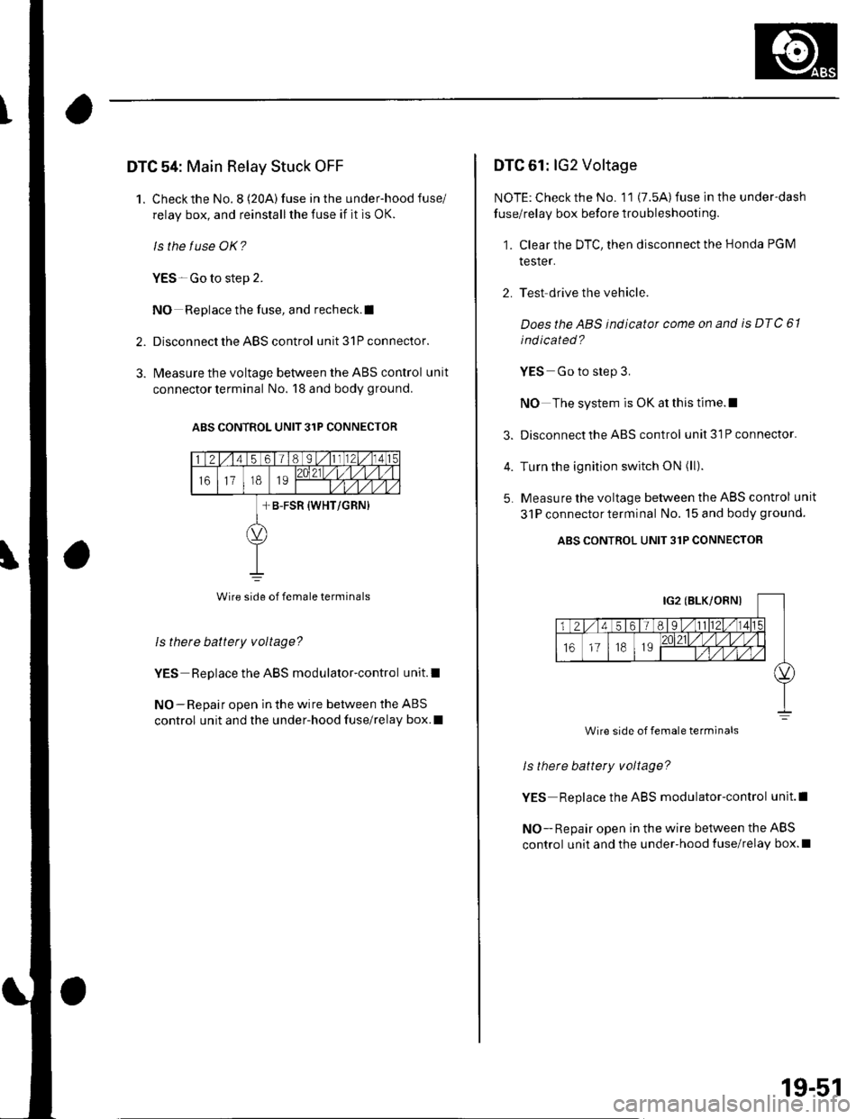
3. l\4easure the voltage between the ABS control unit
connector terminal No. 18 and body ground.
ABS CONTROL UNIT 31P CONNECIOR
Wire side of female terminals
Is there battety voltage?
YES Replace the ABS modulator-control unit.l
NO-Repair open in the wire between the ABS
control unit and the under-hood fuse/relay box.I
DTC 61: lG2 Voltage
NOTE: Check the No. 11 (7.5A) fuse in the under-dash
fuse/relay box before troubleshooting.
1. Clear the DTC, then disconnect the Honda PGM
tesler.
2. Test drive the vehicle.
Doesthe ABS indicator come on and is DTC 61
ind icated ?
YES Go to step 3.
NO The system is OK at this time.l
3. Disconnect the ABS control unit3lPconnector.
4. Turn the ignition switch ON (ll).
5. Measure the voltage between the ABS control unit
31P connectorterminal No. 15 and body ground.
ABS CONTROL UNIT 31P CONNECTOR
ls there battery voltage?
YES Replace the ABS modulator-control unit.l
NO - Repair open in the wire between the ABS
control unit and the under-hood {use/relay box.l
Wire side of female terminals
19-51
Page 646 of 1139
ABS Components
DTC Troubleshooting (cont'd)
DTC 81: CPU (Central Processing Unit)
1. Clear the DTC, then disconnect the Honda PGM
Tester.
2. Test-drive the vehicle.
Does the ABS indicator come on and is DTC 81
indicated ?
YES Replace the ABS modulator-control unit.l
NO-The system is OK at this time. t
19-52
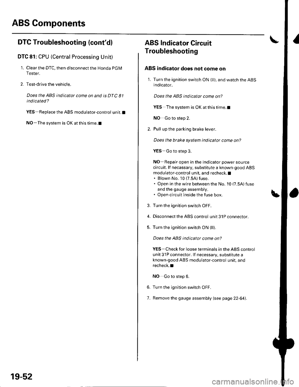
ABS Indicator Gircuit
Troubleshooting
ABS indicator does not come on
1. Turn the ignition switch ON (ll), and watch the ABS
indicator.
Does the ABS indicator come on?
YES The system is OK at this time.I
NO Go to step 2,
Pull up the parking brake lever.
Does the btake system indicator come on?
YES Go to step 3.
NO Repair open in the indicator power source
circuit. lf necassary, substitute a known-good ABS
modulator-control unit, and recheck. I. Blown No, 10 (7.5A) fuse.. Open in the wire between the No. 10 (7.5A)fuse
and lhe gauge assembly,. Open circuit inside the fuse box.
Turn the ignition switch OFF.
Disconnect the ABS control unit 31P connector.
Turn the ignition switch ON (ll).
Does the ABS indicator come on?
YES-Check for loose terminals in the ABS control
unit 31P connector. lf necessary, substitute a
known-good ABS modulator-control unit, and
recheck.l
NO Go to step 6.
Turn the ignition switch OFF.
Remove the gauge assembly (see page 22-64).
3.
5.
6.
7.
Page 647 of 1139
8.
9.
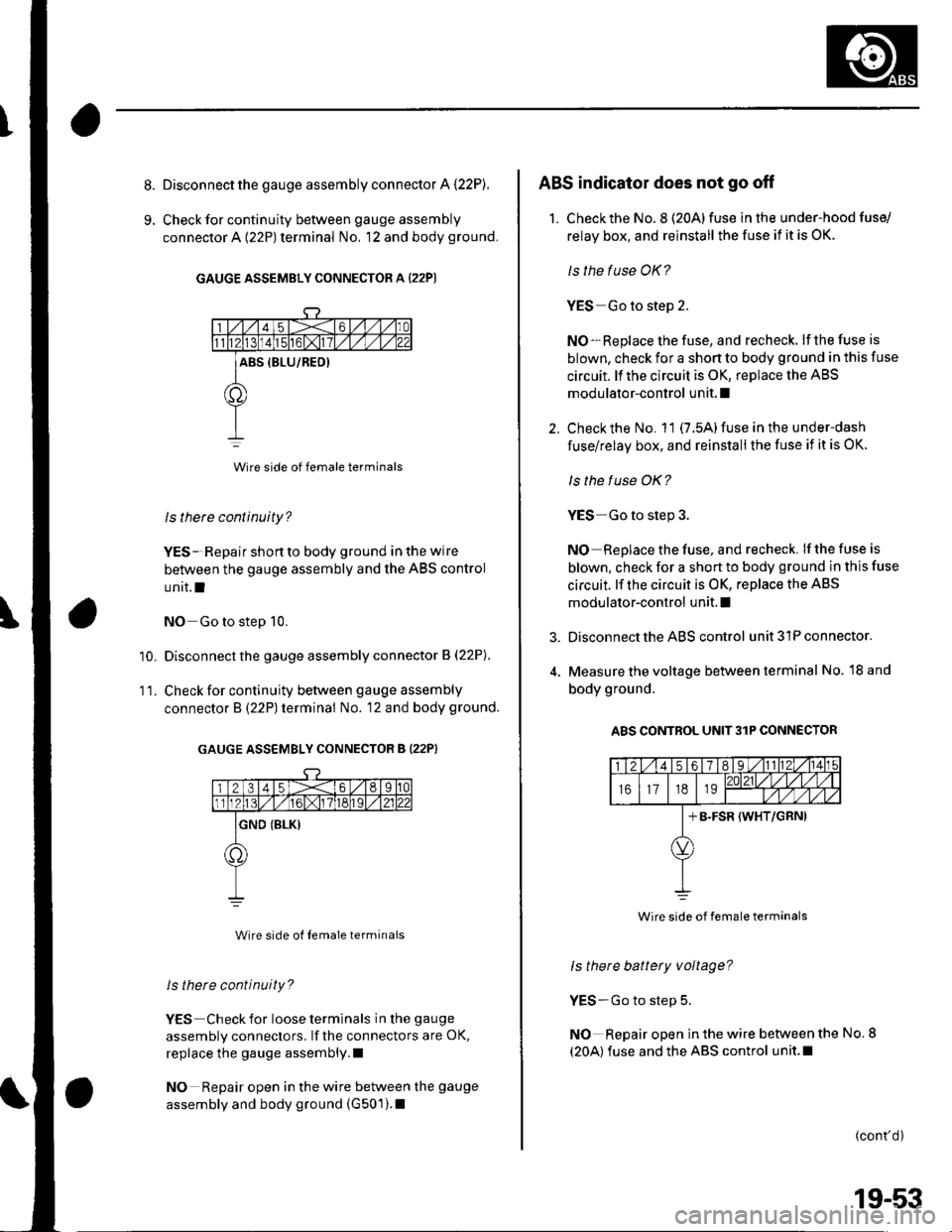
Disconnect the gauge assembly connector A (22P).
Check for continuity between gauge assembly
connector A {22P) terminal No, 12 and body ground.
GAUGE ASSEMBLY CONNECTOR A (22P)
Wire side of female terminals
ls there continuity?
YES- Repair shon to body ground in the wire
between the gauge assembly and the ABS control
unit.l
NO Go to step 10.
Disconnect the gauge assembly connector B (22P).
Check for continuity between gauge assembly
connector B (22P) terminal No. 12 and body ground.
GAUGE ASSEMBLY CONNECTOR B (22PI
Wire side ol Iemale terminals
ls there continuity?
YES Check for loose terminals in the gauge
assembly connectors. lf the connectors are OK,
replace the gauge assembly.l
NO Repair open in the wire between the gauge
assembly and body ground (G501).1
'10.
11.
3.
ABS indicator does not go off
1. Checkthe No. 8 (20Alfuse in the under-hood fuse/
relay box, and reinstall the fuse if it is OK.
ls the fuse OK?
YES Go to step 2.
NO-Replace the fuse, and recheck. lf the fuse is
blown, check for a shon to body ground in this fuse
circuit. ll the circuit is OK, replace the ABS
modulator-control unit. I
Check the No. 11 (7.5A) fuse in the under-dash
fuse/relay box, and reinstall the fuse if it is OK.
ls the f use OK?
YES Go to step 3.
NO Replace the fuse, and recheck. If the fuse is
blown, check for a short to body ground in this fuse
circuit. lf the circuit is OK, replace the ABS
modulator-control unit. I
Disconnect the ABS control unit 31P connector.
Measure the voltage between terminal No. l8 and
body ground.
A8S CONTROL UNIT3lP CONNECTOR
ls there battery voltage?
YES-Go to step 5.
NO Repair open in the wire between the No. 8
(20A) fuse and the ABS control unit.l
(cont'd)
Wire side of female terminals
19-53
Page 648 of 1139
ABS Components
5.
6.
ABS Indicator Circuit Troubleshooting (cont'dl
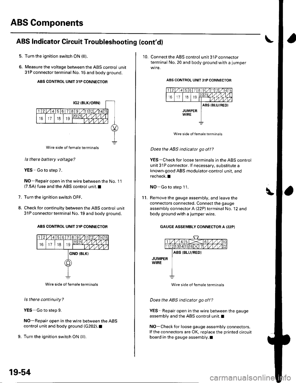
Turn the ignition switch ON (ll).
Measure the voltage between the ABS control unit
31P connector termina I No. 15 and body ground.
ABS CONTROL UNIT 3IP CONNECTOR
Wire side of female terminals
Is there battety voltage?
YES-Go to step 7.
NO-Repair open in the wire between the No. 11(7.5A) fuse and the ABS control unit.I
Turn the ignition switch OFF.
Check for continuity between the ABS control unit
31P connector terminal No. 19 and body ground.
ABS CONTROL UNIT 31P CONNECTOB
Wire side ot Iemale terminals
ls there continuity?
YES Go to step 9.
NO-Repair open in the wire between the ABS
control unit and body ground (G202). t
9. Turn the ignition switch ON (ll).
1.
8.
19-54
10. Connect the ABS control unit3lPconnector
terminal No.20 and body ground with a jumper
wire.
ABS CONTROL UNIT 31P CONNECTOR
Wire side of female terminats
Does the ABS indicator go off?
YES-Check for loose terminals in the ABS control
unil 31P connector. lf necessary, substitute a
known-good ABS modulator-control unit, and
recheck.I
NO Go to step 1 1.
Remove the gauge assembly, and leave the
connectors connected. Connect the gauge
assembly connector A (22P) terminal No. '12 and
body ground with a jumper wire.
GAUGE ASSEMBLY CONNECTOR A (22P)
\'l '1.
Wire side of female terminals
Does the ABS indicator go off?
YES-Repair open in the wire between the gauge
assembly and the ABS control unit.I
NO-Check for loose gauge assembly connectors.
lf the connectors are OK, replace the printed circuit
board in the gauge assembly.l