ect HONDA CIVIC 2003 7.G Workshop Manual
[x] Cancel search | Manufacturer: HONDA, Model Year: 2003, Model line: CIVIC, Model: HONDA CIVIC 2003 7.GPages: 1139, PDF Size: 28.19 MB
Page 684 of 1139
Glass
3.
Ouarter Glass Replacement (cont'dl
Apply protective tape to along the inside and
outside edges of the body. Using an awl, make a
hole through the adhesive from inside the vehicle.
Push a piece of piano wire through the hole, and
wrap each end around a piece of wood.
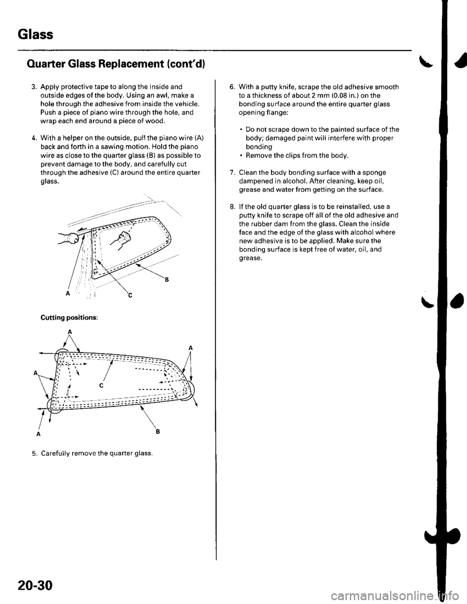
With a helper on the outside, pull the piano wire (A)
back and forth in a sawing motion. Hold the piano
wire as close to the quarter glass (B) as possible to
prevent damage to the body, and carefully cut
through the adhesive (C) around the entire quarter
grass.
Cutting positions:
5. Carefully remove the quarter glass.
20-30
6.With a putty knife, scrape the old adhesive smooth
to a thickness of about 2 mm (0.08 in.) on the
bonding surface around the entire quaner glass
opening flange:
. Do not scrape down to the painted surface of the
body; damaged paint will interfere with proper
bonding. Remove the clips from the body.
Clean the body bonding surface with a sponge
dampened in alcohol. After cleaning. keep oil,
grease and water from getting on the surface.
lf the old quarter glass is to be reinstalled, use a
putty knife to scrape off all of the old adhesive and
the rubber dam from the glass. Clean the inside
face and the edge of the glass with alcohol where
new adhesive is to be applied. Make sure the
bonding su rface is kept free of water, oil, and
grease.
7.
Page 689 of 1139
Moonroof
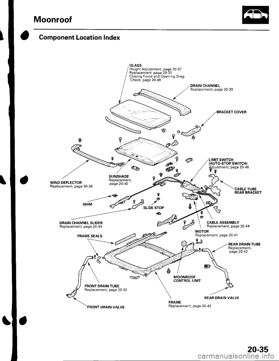
Component Location Index
WIND DEFLECTORReplacement, page 20-38
GLASSHeight Adjustment, page 20 37Replacement, paqe 20-37Closino Force and Ooenino DraoCheck; page 20-48 "
DRAIN CHANNELReplacement, page 20-39
,5
?a<&,
@
..t'- ?.@-@c
_a
@
/,BR^CKEI
COVER
LIMIT SWITCH(AUTO.STOP SWITCH)Adjustment, page 20-46ER
I
CABLE TUBEREAR BRACKETE@
E STOP
.a'
MOONROOFCONTROL UNIT
FRAMEReplacement, page 20-42
CABLE ASSEMBLYBeplacement, page 20-44
*\
)REAR DRAIN VAI-VE
_-""-\q
Replacement, page 20'41
gJ -.- REAR DRA'N TUBE
20-35
Page 690 of 1139
Moonroof
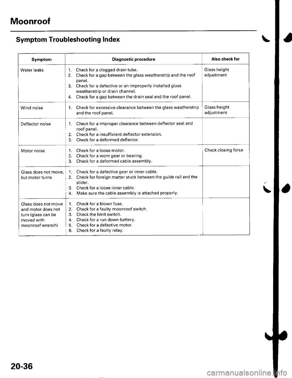
Symptom Troubleshooting Index
SymptomDiagnostic procedureAlso check for
Water leaks'1. Check for a clogged drain tube.
2. Check for a gap between the glass weatherstrip and the roof
panel.
3. Check for a defective or an improperly installed glass
weatherstrip or drain channel.
4. Check for a gap between the drain seal and the roof panel.
G lass height
adJustment
Wind nolse1. Check for excessive clearance between the glass weatherstrip
and the root panel.
Glass height
adjustment
Deflector noise1. Check for a imDrooer clearance between deflector seal and
roof panel.
2, Check for a insufficient deflector extension.
3. Check for a deformed deflector.
Motor noise1. Check for a loose motor.
2. Check for a worn gear or bearing.
3. Check for a deformed cable assembly.
Check closing force
Glass does not move,
but motor turns
1. Check for a defective gear or inner cable.
2. Check for foreign matter stuck between the guide rail and the
slide r.
3. Check for a loose inner cable.
4. l\,4ake sure the cable assembly is attached properly.
Glass does not move
and motor does nol
turn (glass can be
moved with
moonroof wrench)
1. Check for a blown fuse.
2. Check for a faulty moonroof switch.
3. Check the limit switch.
4. Check for a run down battery.
5. Check for a defective motor.
6. Check for a faulty relay.
20-36
Page 692 of 1139
Moonroof
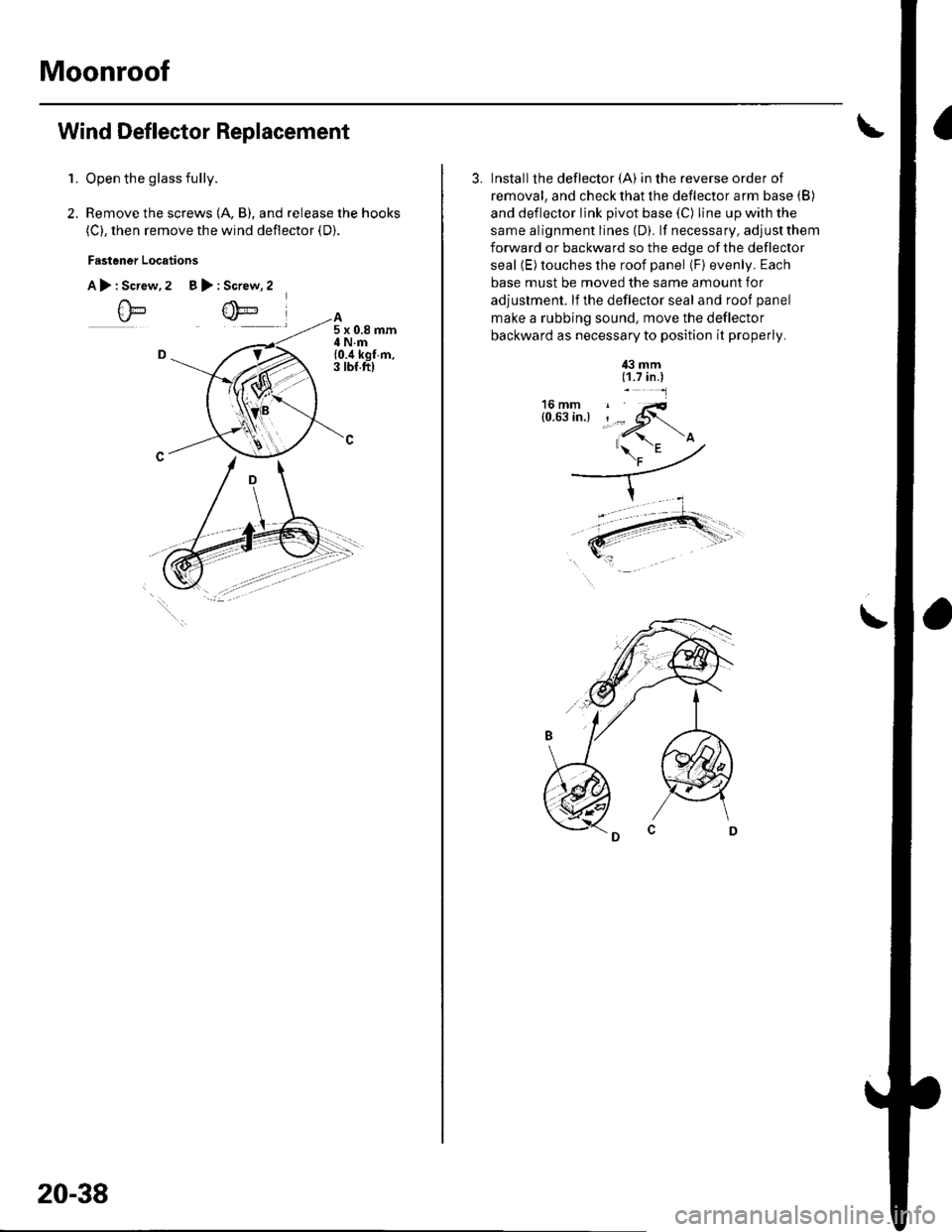
Wind Deflector Replacement
2.
1.Open the glass fully.
Remove the screws (A, B), and release the hooks
(C), then remove the wind deflector (D).
Fastener Locations
A>:Screw,2 B>:Screw, 2
20-38
3. Installthe deflector (A) in the reverse order of
removal, and check that lhe deflector arm base (B)
and deflector link pivot base (C) line up with the
same alignment lines (D). lf necessary, adjust them
forward or backward so the edge of the deflector
seal (E) touches the roof panel (F) evenly. Each
base must be moved the same amount for
adjustment. lf the deflector seal and roof panel
make a rubbing sound, move the deflector
backward as necessary to position it properly.
4il mm(1.7 in.)_-l
'a- -' -
\
Page 695 of 1139
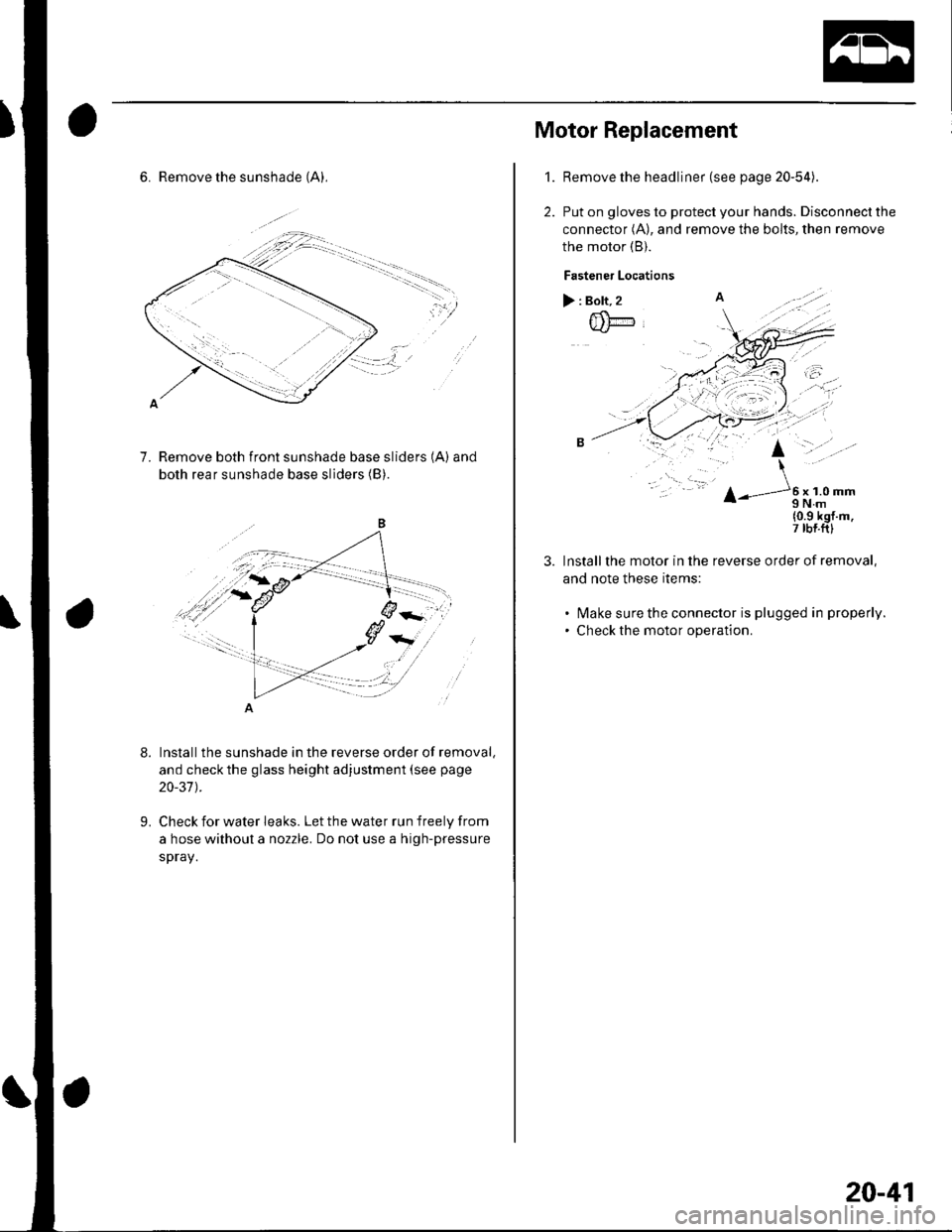
6. Remove the sunshade (A),
::lll' =r'"'---
----.-.. --.,
'l'i
?,
7.Remove both front sunshade base sliders (A) and
both rear sunshade base sliders (B)
t'-^'
'a{
8.
9.
Installthe sunshade in the reverse order of removal,
and check the glass height adjustment (see page
20-37 ).
Check for water leaks. Let the water run freely from
a hose without a nozzle. Do not use a high-pressure
spray.
1.
Motor Replacement
Remove the headliner (see page 20-54).
Put on gloves to protect your hands. Disconnecl the
connector (A), and remove the bolts, then remove
the motor (B).
Fastener Locations
>:Bolt,2 A
@@
..
{0.9 kgf.m.7 rbf.ftl
Installthe motor in the reverse order of removal,
and note these items:
. lvlake surethe connector is plugged in properly.
. Check the motor operation.
20-41
Page 696 of 1139
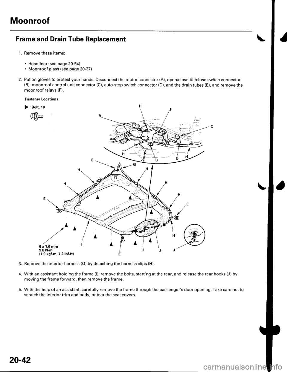
Moonroof
1.
Frame and Drain Tube Replacement
Remove these items:
. Headliner (see page 20-54). Moonroof glass (see page 20-37)
Put on gloves to protect you r hands. Disconnect the motor connector (A), open/close-tilt/close switch connector
{B), moonroof control unit connector {C), auto-stop switch connector (D), and the drain tubes (Ei, and remove the
moonroof relays (F).
Fastenor Locations
> : Bolt, 10
{um
/^
6x1.0mm9.8 N.m(1.0 kgf.m,7.2lbf ft)
4.
5.
2.
irl
@
Remove the interior harness (G) by detaching the harness clips (H).
With an assistant holding the frame (l). remove the bolts, starting at the rear, and release the rear hooks (J) by
moving the f rame forward, then remove the frame.
With the help of an assistant, carefully remove the frame through the passenger's door opening. Take care not to
scratch the interior trim and body, or tear the seat covers.
20-42
Page 697 of 1139
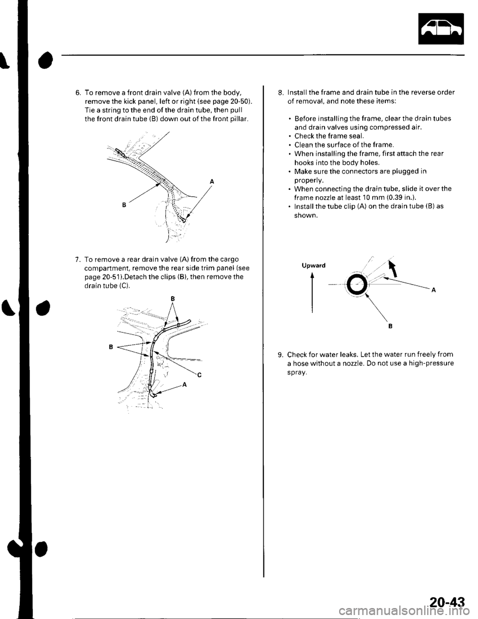
6. To remove a front drain valve (A)from the body,
remove the kick panel, left or right (see page 20-50).
Tie a string to the end of the drain tube, then pull
the front drain tube (B) down out of the front pillar.
To remove a rear drain valve (A) from the cargo
compartment, remove the rear side trim panel (see
page 20-51).Detach the clips (B), then remove the
drain tube (C),
B
1.
8. Installthe frame and drain tube in the reverse order
of removal, and note these items:
. Before installing the frame, clear the drain tubes
and drain valves using compressed air.. Check the frame seal.. Clean the surface ofthe frame.. When installing the frame, first attach the rear
hooks into the body holes.. Make sure the connectors are plugged in
properly.
. When connecting the drain tube, slide it overthe
frame nozzle at least 10 mm (0.39 in.)..Installthetubeclip(A) on the drain tube (B) as
shown.
Upward
t-
I
I
B
Check for water leaks. Let the water run freely from
a hose without a nozzle. Do not use a high-pressure
spray.
9.
20-43
Page 698 of 1139
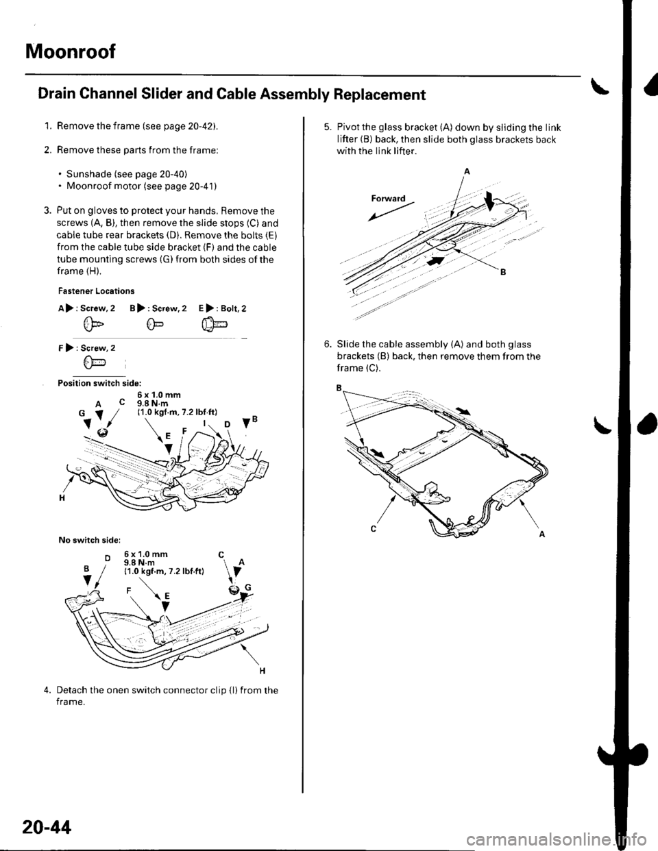
Moonroof
Drain Channel Slider and Cable Assembly Replacement
1. Remove the frame (see page 20-42).
2. Remove these parts from the frame:
. Sunshade (see page 20-40). Moonroof motor (see page 20-41)
3. Put on gloves to protect your hands, Remove the
screws (A, B), then remove the slide stops (C) and
cable tube rear brackets (D). Remove the bolts (E)
from the cable tube side bracket (F) and the cable
tube mounting screws (G) from both sides of the
frame (H).
Fastener Locations
A> r Screw.2 B): Screw,2
@@
r):
Position switch side:
6x1.0mmA c g,a N.m
No switch sidel
o
E>:Bolt,2
Screw
6\-'1
6x1.0mm C9.8 N.m11.0 kgf.m, 7.2 lbf.ft)
Detach the onen switch connector clip {l)from the
frame.
B
V
20-44
5. Pivotthe glass bracket (A) down by sliding the link
lifter (B) back, then slide both glass brackets back
with the link lifter.
Slide the cable assembly (A) and both glass
brackets (B) back, then remove them from the
frame (C).
Page 702 of 1139
Moonroof
\
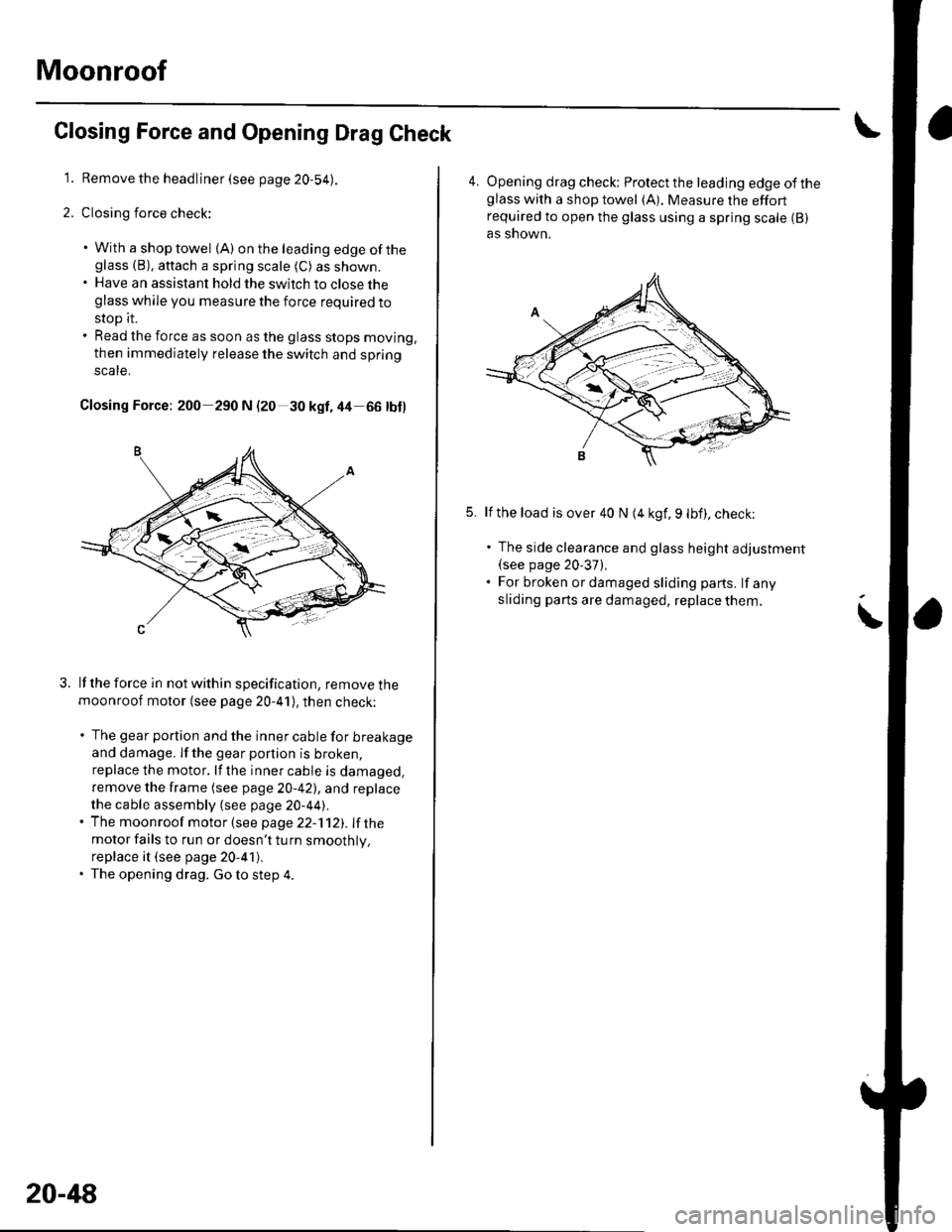
Closing Force and Opening Drag Check
1. Remove the headliner (see page 20-54).
2. Closing force check:
. With a shop towel {A) on the leading edge of theglass (B), aftach a spring scale (C) as shown.. Have an assistant hold the switch to close theglass while you measure the force required to
stop it.. Read the force as soon as the glass stops moving,
then immediately release the switch and spring
scale.
Closing Force; 200 290 N (20 30 kgf,44 66 tbl)
lf the force in not within specification, remove themoonroof motor (see page 20-41), then check:
. The gear portion and the inner cable for breakageand damage. lf the gear portion is broken,
replace the motor. lf the inner cable is damaged,
remove the frame (see page 20-42), and replace
the cable assembly (see page 20-44).' The moonroof motor (see page 22-112). Ifthe
motor fails to run or doesn't tu rn smoothlv.
replace it (see page 20-41),. The opening drag. Go to step 4.
20-48
4. Opening drag check: Protect the leading edge of theglass with a shop towel (A). Measure the effortrequired to open the glass using a spring scale (B)
as shown.
5.lf the load is over 40 N (4 kgf, 9 lbf), check;
. The side clearance and glass height adjustment(see page 20'37),. For broken or damaged sliding parts. lf any
sliding parts are damaged, replace them.
Page 704 of 1139
Interior Trim
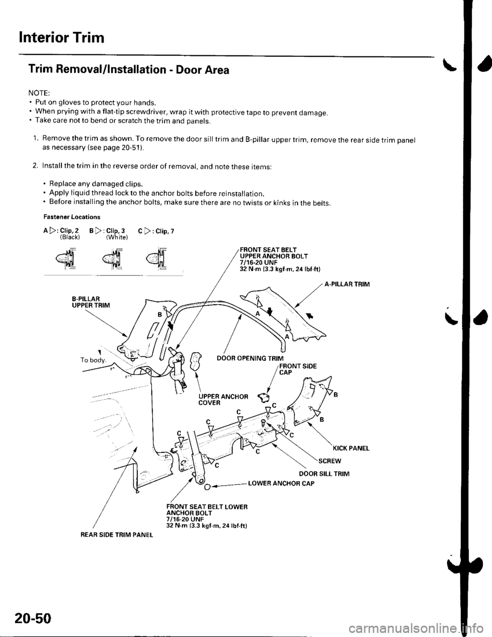
Trim Removal/lnstallation - Door Area
NOTE:. Put on gloves to protect your hands.. When prying with a flat-tip screwdriver, wrap it with protective tape to prevent damage.. Take care not to bend or scratch the trim and panels.
1. Remove the trim as shown. To remove the door silltrim and B-pillar upper trim, remove the rear side trim panelas necessary (see page 20-51).
2. Installthe trim in the reverse order of removal, and note these items:
. Replace any damaged clips.. Apply liquid thread lock to the anchor bolts before reinstallatior,.. Before installing the anchor bolts, make sure there are no twists or kinks in the belts.
Fastener Locations
B>rClip,3 C>:Clip,?{White)
FRONT SEAT BELTUPPER ANCHOR BOLT7/16-20 UNF32 N m (3.3 kgf m,24 lbf.ft)
A-PILLAR TRIM
il-::7
/ ao----- LowER ANcHoR cAP
FRONT SEAT BELT LOWERANCHOR BOLT7/16-20 UNF32 N.m (3.3 kgt.m,24lbl.ftl
,"lF
{
A >: Clip,2(Black)
2ffi
Tl|t
\
KICK PANEL
REAR SIDE TRIM PANEL
20-50