Panel HONDA CIVIC 2003 7.G Repair Manual
[x] Cancel search | Manufacturer: HONDA, Model Year: 2003, Model line: CIVIC, Model: HONDA CIVIC 2003 7.GPages: 1139, PDF Size: 28.19 MB
Page 797 of 1139
Heating and Air Conditioning
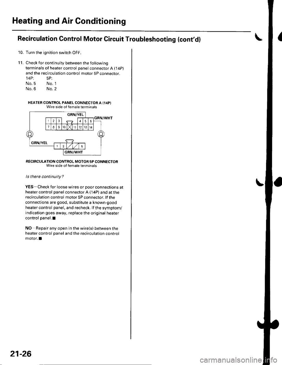
Recirculation Control Motor Circuit Troubleshooting (cont'd!
10. Turn the ignition swirch OFF.
11. Check for continuity between the following
terminals of heater control panel connector A ( 14P)
and the recirculation control motor 5P connector.'l4Pt 5P:
No.5 No. 1
No.6 No.2
HEATER CONTROL PANEL CONNECTOR A {14P}Wire side ol temale terminats
RECIRCULATION CONTROL MOTOR 5P CONNECTORWire side ol lemale terminals
ls there continuity?
YES Check for loose wires or poor connections at
heater control panel connector A ( 14P) and at the
recirculation control motor 5P conneclor. lf the
connections are good, substitute a known-good
heater control panel, and recheck. lf the symptom/
indication goes away, replace the original heater
control panel,I
NO Repair any open in the wire{s) between the
heater control panel and the recirculation control
motor.l
21-26
Page 798 of 1139
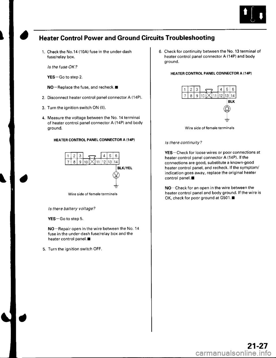
Heater Control Power and Ground Circuits Troubleshooting
1. Check the No.14 (10A)fuse in the under-dash
fuse/relay box.
ls the f use OK?
YES-Go to step 2.
NO-Replace the fuse, and recheck.l
2. Disconnect heater control panel connectorA{'14P).
3. Turn the ignition switch oN (ll).
4. Measure the voltage between the No. l4terminal
of heater control panel connector A (14P) and body
grouno.
HEATER CONTROL PANEL CONNECTOR A {14P}
23456
78I10 l,111214
Wire side of temale terminals
BLK/YEL
ls there battery voltage?
YES-Go to step 5.
NO Repair open in the wire betvveen the No. 14
fuse in the under-dash fuse/relay box and the
heater control panel.l
Turn the ignition switch OFF.
6. Check for continuity between the No. l3terminal of
heater control panel connector A (14P) and body
g rou nd.
HEATER CONTRoL PANEL CONNEcToR A (1ilP)
123456
I89r0 t,1l1214
BLK
.o
Wire side of temaleterminals
ls therc continuity?
YES Check for loose wires or poor connections at
healer control panel connector A (14P). lfthe
connections are good, substitute a known-good
heater control panel, and recheck. lf the symptom/
indication goes away, replace the original heater
control panel.l
NO Check for an open in the wire between the
heater control panel and body ground. lf the wire is
OK, check for poor ground at G501. I
21-27
Page 803 of 1139
Heating and Air Conditioning
Compressor Clutch Circuit
Troubleshooting (cont'dl
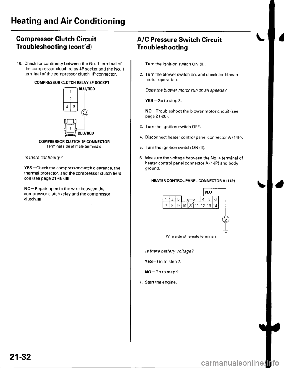
16. Check for continuity between the No. lterminal of
the compressor clutch relav 4P socket and the No. l
terminal of the compressor clutch 1P conneclor.
COMPRESSON CLUTCH RELAY 4P SOCKET
COMPRESSOR CLUTCH 1P CONNECTORTerminal side of male terminals
ls therc continuity?
YES-Check the compressor clutch clearance, the
thermal protector, and the compressor clutch field
coil (see page 21-48).I
NO-Repair open in the wire between the
compressor clutch relay and the compressor
clutch.l
21-32
A/C Pressure Switch Circuit
Troubleshooting
'1. Turn the ignition switch ON {ll).
2. Turn the blower switch on, and check for blower
motor operatron.
Does the blower motor run on all speeds?
YES Go to step 3.
NO Troubleshoot the blower motor circuit (see
page 21-20).
3. Turn the ignition switch OFF.
4. Disconnect heater control panel connectorA ('14P).
5. Turn the ignition switch ON (ll).
6. Measure the voltage between the No, 4 terminal of
heater control panel connector A {14P) and body
grou nd.
HEATER CONTROL PANEL CONNECTOR A (I4P}
1.
ls there battety voltage?
YES Go to step 7.
NO-Go to step 9.
Stan the engine.
Wire side of female termina's
Page 804 of 1139
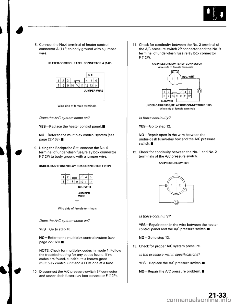
8. Connect the No.4 terminal ofheatercontrol
connector A (14P) to body ground with a jumper
wire,
HEATER CONTROL PANEL CONNECTOR A I14P}
BLU
23456
78Ir0lx1112l3t4
JUMPER WIBE
Wire side of female terminals
Does the A/C system come on?
YES Replace the heater control panel.!
NO Refer to the multiplex control system (see
page 22-168).1
Using the Backprobe Set, connect the No. 9
terminal of under-dash fuse/relay box connector
F (12P) to body ground with a jumper wire.
UNOER.DASH FUSE/RELAY BOX CONNECTOR F {12P}
9.
25
61B g lrotll2
BLU/WHT
JUMPERWIRE
Wire side of female terminals
Does the NC system come on?
YES Go to step 10.
NO- Refer to the multiplex control system (see
page 22-168).1
NOTE: Check for multiplex codes in mode '1. Follow
the troubleshooting {or any codes found. lf no
codes are found, subsititute a known-9ood
multiplex control unit and a ECM one at a time.
Disconnect the Ay'C pressure switch 2P connector
and under-dash fuse/relay box connector F { 12P).
10.
'13.
21-33
11. Check for continuity between the No. 2 terminal of
the A,/C pressure switch 2P connector and the No. 9
terminal of under-dash fuse relav box connector
F t12Pt.
A/C PRESSURE SWITCH 2PCONNECTORWire side of female terminals
UNDER.OASH FUSE/RELAY BOX CONNECTOR F (12P)
Wire side of fenale lerrrinal'
ls there continuity?
YES Go to step 12.
NO Repair open in the wire between the
under-dash fuse/relay box and the A,,/C pressure
switch.I
Check for continuity between the No. 1 and No. 2
terminals of the A,/C pressure switch.
12.
A/C PRESSURE SWITCH
ls there continuity?
YES Repair open in the wire between the heater
control panel and the A,/C pressure switch.l
NO Go to step 13.
check for proper Ay'C system pressure.
ls the pressure within specitications?
YES Replace the AilC pressure switch.l
NO Repair the AilC pressure problem.I
Page 809 of 1139
Heating and Air Gonditioning
a
\
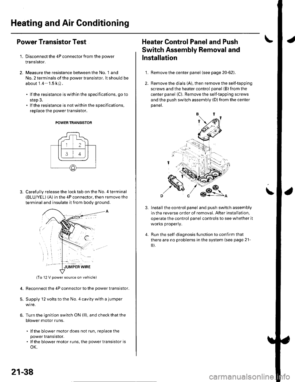
Power Transistor Test
1. Disconnect the 4P connector from the power
Iranslslor.
2, Measure the resistance between the No. 1 and
No. 2 terminals of the power transistor. lt should be
about '1.4 1.5 kQ.
. lf the resistance iswithln the specifications, go to
step 3.. lf the resistance is notwithin the specifications,
replace the power transistor.
POWER TRANSISTOB
Carefully release the lock tab on the No. 4 terminal(BLUI/EL) (A) in the 4P connector, then remove the
terminal and insulate it from body ground.
(To 12 V power source on vehicle)
Reconnect the 4P connector to the power transistor.
Supply 12 volts to the No. 4 cavity with a jumper
wire.
Turn the ignition switch ON (ll), and check that the
blower motor runs.
. lf the blower motor does not run, replace the
power rranstsror.. lf the blower motor runs,the powertransistoris
oK.
12 V power source on vehicle)
21-38
1.
Heater Control Panel and Push
Switch Assembly Removal and
Installation
Remove the center panel (see page 20-62).
Remove the dials (A), then remove the self-tapping
screws and the heater control panel (B)from the
center panel (Cl. Remove the self-tapping screws
and the push switch assembly (D)from the center
panel.
lnstall the control panel and push switch assembly
in the reverse order of removal. After installation,
operate the control panel controls to see whether it
worKs propeny.
Run the self-diagnosis function to confirm that
there are no problems in the system (see page 21-
8).
3.
4.
Page 810 of 1139
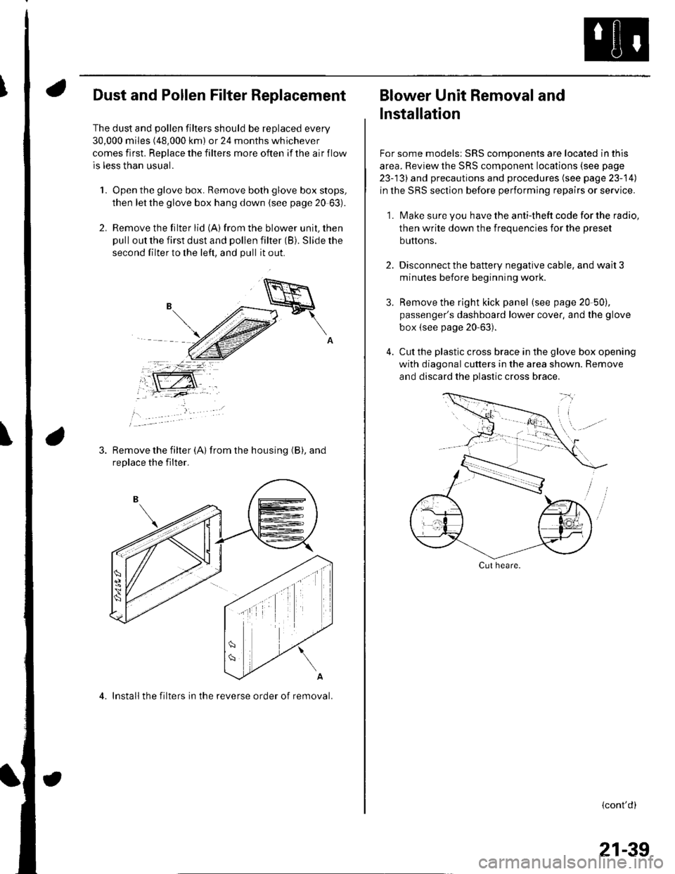
Dust and Pollen Filter Replacement
The dust and pollen filters should be replaced every
30,000 miles (48.000 km) or 24 months whichever
comes first. Replace the filters more often if the air flow
is less than usual.
1. Open the glove box. Remove both glove box stops,
then let the glove box hang down (see page 20 63).
2. Remove the filter lid (A)from the blower unit, then
pull out the first dust and pollen filter (B). Slide the
second filter to the left, and pull it out.
Remove the filter {A) from the housing (B), and
replace the filter.
4. Install the filters in the reverse order of removal.
Blower Unit Removal and
lnstallation
For some models: SRS components are located in this
area. Review the SRS component locations (see page
23-13) and precautions and procedures (see page 23-14)
in the SRS section before performing repairs or service.
1. Make sure you have the anti-theft code for the radio,
then write down the frequencies for the preset
buttons.
2. Disconnect the battery negative cable, and wait 3
minutes before beginning worK.
3. Remove the right kick panel (see page 20-50),
passenger's dashboard lower cover, and the glove
box {see page 20-63).
4. Cut the plastic cross brace in the glove box opening
with diagonal cutters in the area shown. Remove
and discard the plastic cross brace,
Cut heare.
{cont'd)
21-39
Page 857 of 1139
Connectors and Harnesses
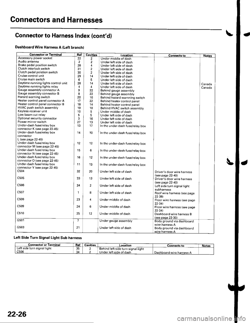
Dashboard Wire Harness A {Left branchl
Connector or TerminalffiAccessory power socketAudio antennaBrake pedal position switchClutch interlock switchClutch pedal poistion switchCruise control unitCruise main switchDaytime r!nning lights control unitDaytime running lights relayGauge assembly connector AGauge assembly connector BHazard warning switchHeater control panel connector AHeater control panel connector BHVAC push switch assemblyKeyless receiver unitLow beam cut relayOptional security connectorPower mirror switchUnder-dash fuse/relay boxconnector K (see page 22-45)Under'dash fuse/relay box
L {see page 22-45}Underdash fuse/relay boxconnector M lsee page 22'45)Under-dash fuse/relay boxconnector N (see page 22-45)UndeFdash fuse/relay boxconnector O (see page 22-45)UndeFdash fuse/relay boxconnectorY (see page 22 45)c504
c505
c506
c507
c508
c509
c510
22226
3029628
I820111819105327
,I4
12
11
34
1
24
25
2 Under middle of dash2 Under left side of dash4 ] Under left side of dash2 ] Under left srde of dash2 | Under left side of dash14 I Under left side of dash5 Under left side of dash14 Under lett side of dash4 Under lett side of dash22 I Behind gauge assembly22 i Behind gauge assembly10 Behind hazard warnning switch22 Behind heater control panel'14 Behind heater control panel10 ] Behind HVAC switch assembly5 I Under middle of dash5 lUnderleftsideofdash16 Under lefr side of dash13 Under left side oI dash17 ln the under-dash fuse/relay box
CanadaCanada
l0In the under-dash fuse/relay box
In the undeFdash fuse/relay box
In the underdash fuse/relay box
In the under-dash fuse/relay box
In the under-dash fuse/relay box
Under left side of dash
Under left side ot dash
Under left side of dash
Under left side of dash
Under middle of dash
Under middle of dash
Under middle ol dash
Driver's door wire harness(see page 22'40)Driver's door wire harness(see page 22-40)Left side turo signal lightsuonarnessRoof wire harness (see page22 3AlFloor wire harness {see page22-341Floor wire harness (see page22 34JDashboard wire harness B(see oaoe 22-30)
12
12
G501
G503
1
21
Under gauge assembly
Under left side of dash
Body ground via dashboard
Body ground via dashboard
Left Side Turn Signal Light Sub harness
Connector to Harness Index (cont'd)
L
Connector or TerminalCavitiesLocationConnects toNolesLeft side turn signal lightc506353422Behind left side turn signal lightUnder left side of dashDashboard wire harness A
22-26
Page 867 of 1139
Gonnectors and Harnesses
a
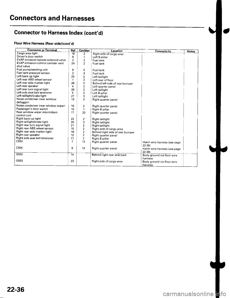
Floor Wire Harness {Rear side}(cont'dl
Cargo areaDriver's door switchEVAP emission bypass solenoid valveEVAP emission control canister ventshut valveFuel pump/sending unitFuel tank pressure sensorLeft back-up lightLeft rear ABS wheel sensorLeft rear side marker lightLeft rear speakerLeft rear turn signal lightLeft side seat belt tensionerLeft taillighVbrake lightNoise condenser (rear windowdefogger)Noise condenser (rear window wiper)Passenger's door switchRear window wiper intermiftentcontrolunitRight back-up lightRight taillighvbrake tightRight rear turn signal lightBight rear ABS wheel sensorRight rear side marker lightRight rear speakerRight side seat belt tensioner
c554
Fueltank
FueltankFueltankLeft taillightLeft rear offloorBehind left side of rear bumperLeft quarter panelLefttaillightLeft B-pillarLeft taillightRight quarter panel
Right quarter panelRight B pillarRight q uarter panel
Right tai ightRight taillightRight taillightRight side of cargo area
side of cargo areaLeft B pillarFueltank
Right quaner panel
6224
I32512642A527'13
181011
222021151912117
I
2122
5322222232
232222212
12
2120
Behind right side of rear bumperRight quaner panelRight B-pillarRight quaner panelHatch wire harness (see page22 39)Hatch wire harness (see page
rear seal bdcl Bodv ground vta
Right side of cargo area Body ground via floor wire
Connector to Harness Index (cont'dl
22-36
Page 870 of 1139
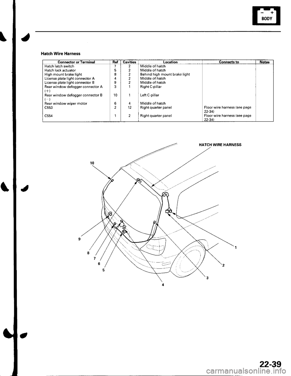
Hatch Wire Harness
Connector or TorminalCavitiesLocationConnects toNotesHatch latch switchHatch lock actuatorHigh mount brake lightLicense plate light connector ALicense plate light connector BRear window de{ogger connector A
Bear window detogger connector B()Bear window wiper moto.c553
c554
7
8
I3
10
62
l
222221
1
412
2
Middle o{ hatchMiddle of hatchBehind high mount brake lightMiddle of hatchMiddle of hatchRight C-pillar
Left C-pillar
Middle of hatchRight quaner panel
Right quaner panel
Floor wire harness (see page22-341Floor wire harness (see page)2-34\
22-39
Page 878 of 1139
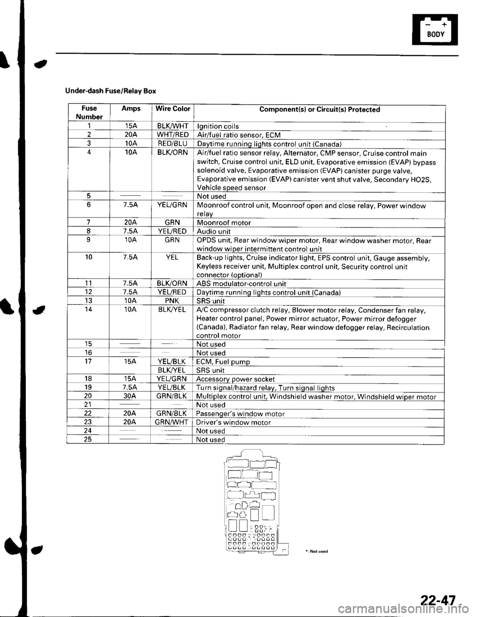
Under-dash Fuse/Relay Box
Fuse
Number
AmpsWire ColorComponent(s) or Circuit(s) Protected
115ABLKA/VHTlgnition coils
2204WHT/REDAirlfuel ratio sensor, ECM
310ARED/BLUDaytime running Iights control unit {Canada)10ABLI(ORNAir/fuel ratio sensor relay, Alternator, CMP sensor, Cruise control main
switch, Cruise control unit. ELD unit, Evaporative emission (EVAP) bypass
solenoid valve, Evaporative emission (EVAP)canister purge valve,
Evaporative emission (EVAP) canister vent shut valve, Secondary H02S,
Vehicle speed sensor
5Not used
67.5AYEUGRNMoonroof control unit, Moonroof open and close relay, Power window
relaV
7204GRNMoonroof motor
I7.5AYEUREDAudio unit
910AGRNOPDS unit, Rear window wiper motor, Rear window washer motor, Rear
window wiper intermittent control unit
107.54YELBack-up lights, Cruise indicator light, EPS control unit, Gauge assembly,
Keyless receiver unit, Multiplex control unit, Security control unit
connector (optional)
117.5ABLIVORNABS modulator-control unit
127.5AYEUREDDaytime runnino liohts control unit (Canada)
1310APNKSRS unit't410ABLK/YE LA,,/C compressor clutch relay, Blower motor relay, Condenser fan relay,
Heater control panel, Power mirror actuator, Power mirror defogger(Canada), Radiator fan relay, Rear window defogger relay, Recirculation
control motor1ENot used
loNot used
1715AYE L/B LKECM, Fuel pump
B LK/YE L>H> Unrr
1815AYEUGRNAccessory power socket
197.5AYEUBLKTurn siqnal/hazard relav, Turn siqnal liohts
2030AGRN/BLKMultiplex control unit, Windshield washer motor. Windshield wioer motor21Not used
22204GRN/BLKPassenqer's window motor
2320A.G R N,A/VHTDriver's window motor
24Not used
25Not used
__^:Hr tl_l
f at-t
at I
r^,rl fl
!!;r -
!339,i;s!!sf Fnf : |rnITf
22-47