light HONDA CIVIC 2003 7.G Repair Manual
[x] Cancel search | Manufacturer: HONDA, Model Year: 2003, Model line: CIVIC, Model: HONDA CIVIC 2003 7.GPages: 1139, PDF Size: 28.19 MB
Page 683 of 1139
19. Use suction cups to hold the rear window over the
opening. align it with the alignment marks you
made in step '13, and set it down on the adhesive.
Lightly push on the rear window until its edges are
fully seated on the adhesive all the way around. Do
not open or close the doors until the adhesive is dry.
20. Scrape or wipe the excess adhesive off with a putty
knife or towel. To remove adhesive from a painted
surface or the rear window, use a soft shop towel
dampened with alcohol.
21. Let the adhesive dry for at least 'l hour,thenspray
water over the rear window and check for leaks.
Mark the leaking areas, let the rear window dry,
then seal with sealant. Let the vehicle stand for at
least 4 hours after rear window installation, lf the
vehicle has to be used within the first 4 hours, it
must be driven slowly.
22. Reinstallall remaining removed parts.
NOTE: Advise the customer not to do the following
things for 2 to 3 days:
. Slam the doors with all the windows rolled up.. Twist the body excessively (such as when going
in and out of driveways at an angle or driving
over rough, uneven roads).
Ouarter Glass Replacement
NOTE:. Put on gloves to protect your hands.. Wear eye protection while cufting the glass adhesive
with piano wire,. Use seat covers to avoid damaging any surfaces.
1. Remove the C-pillar trim (see page 20-51).
lf necessary, remove the rear side trim panel (see
page 20-51 ) and B-pillar upper trim (see page 20-
50).
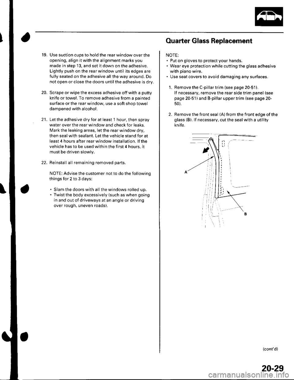
2. Remove the front seal {A) from the front edge of the
glass (B). lf necessary, cut the seal with a utility
knife.
(cont'd)
20-29
Page 686 of 1139
Glass
Ouarter Glass Replacement (cont'dl
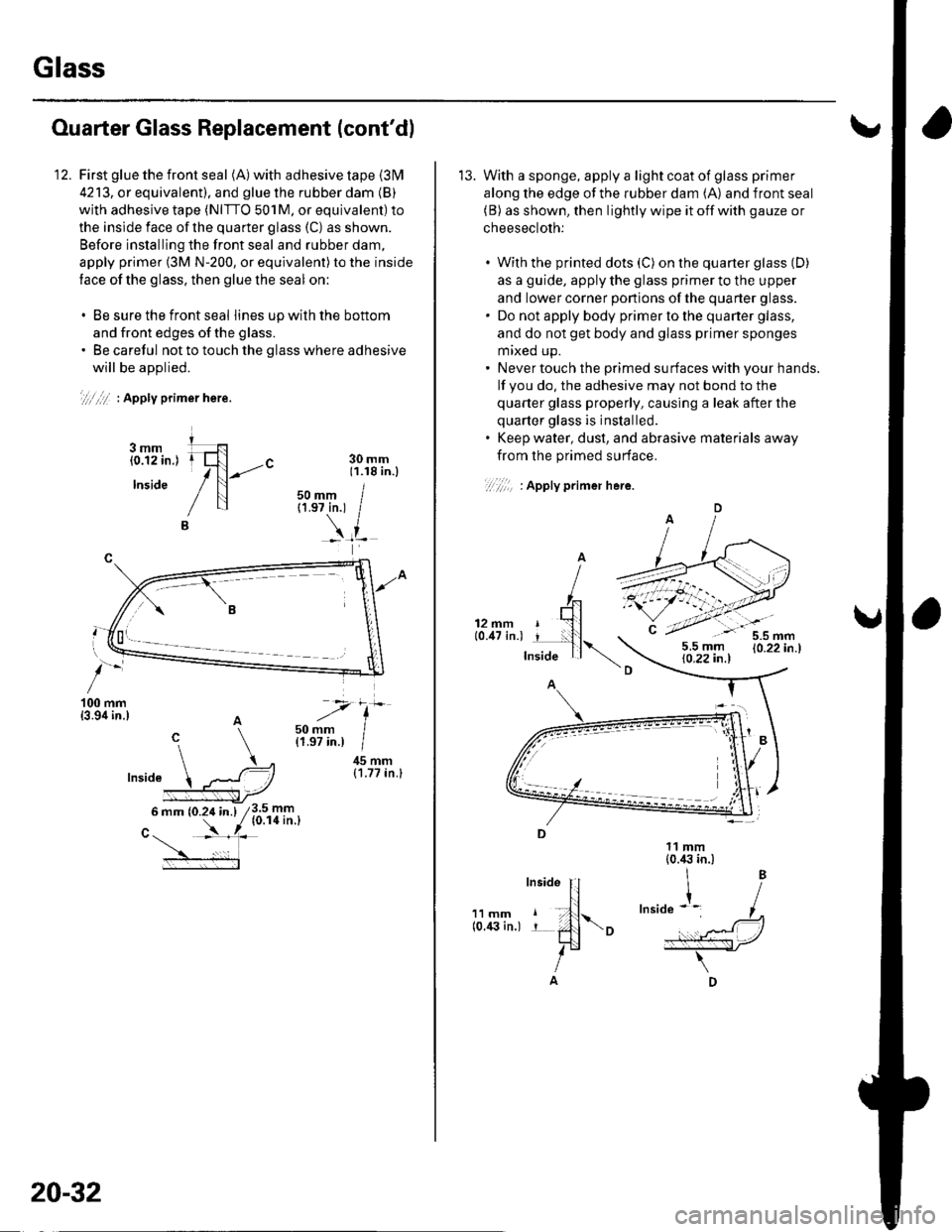
First glue the front seal (A) with adhesive tape {31\4
4213, or equivalent). and glue the rubber dam (B)
with adhesive tape (NITTO 501M, or equivalent) to
the inslde face of the quarter glass (C) as shown.
Before installing the front seal and rubber dam,
apply primer (3M N-200, or equivalent)to the inside
tace of the glass. then glue the seal on:
. Be sure the front seal lines upwiththe bottom
and front edges of the glass.. Be careful not to touch the glass where adhesive
will be aoolied.
.,1.,,/:/ | Apply prlJner hete.
-"-c
i--l
'100 mm{3.9i1in.)
45 mm{1.77 in.}
3.5 mm{0.r4 in.l
30 mm11.18 in.l
50 mm I{1.97in.1 /
6 mm (0.24 in.)
nLv--
20-32
'13. With a sponge, apply a light coat of glass primer
along the edge of the rubber dam (A) and front seal(B) as shown, then lightly wipe it off with gauze or
cheesecloth:
With the printed dots (C) on the quarter glass (D)
as a guide, apply the glass primer to the upper
and lower corner ponions of the quarter glass.
Do not apply body primer to the quaner glass,
and do not get body and glass primer sponges
mrxed up.
Never touch the primed surfaces with your hands.
lf you do, the adhesive may not bond to the
quarter glass properly, causing a leak after the
quarter glass is inslalled.
Keep water, dust, and abrasive materials away
from the primed surface.
11 mmlo.i(} in.)
Page 687 of 1139
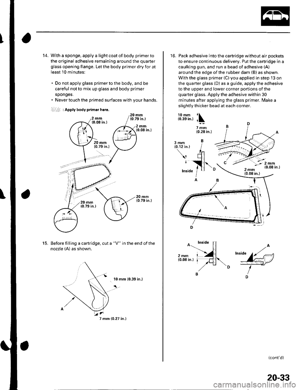
14, With a sponge. apply a light coat of body primer to
the original adhesive remaining around the quarter
glass opening flange. Let the body primer dry for at
least 10 minutes:
. Do not apply glass primer to the body, and be
careful not to mix up glass and body primer
sponges.. Never touch the primed surfaces with your hands.
)'/ii ,/ii. I Apply bodv prime. here,
mm(0.08 in.l
20 mm(0.79 in.)
2mm{0.08 in.)
Before filling a cartridge, cut a "V" in the end ofthe
nozzle (A) as shown.
'10 mm (0.39 in.)
20 mm{0.79 in.)
t5.
7 mm 10.27 in.)
20-33
16. Pack adhesive into the cartridge without air pockets
to ensure continuous delivery. Put the cartridge in a
caulking gun, and run a bead of adhesive (A)
around the edge of the rubber dam (B) as shown.
With the glass primer (C)you applied in step 13 on
the quarter glass (D) as a guide. apply the adhesive
to the upper and lower corner portions of the
quarter glass. Apply the adhesive within 30
minutes after applying the glass primer. lvlake a
slightly thicker bead at each corner.
l.:J611, ;\
7mm{0.28 in.)
3mm{0.'12 in.}
I
IA
(conl'd )
Page 688 of 1139
Glass
Ouarter Glass Replacement (cont'd)
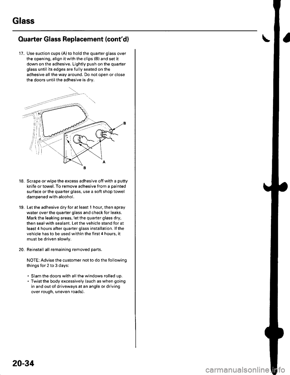
17. Use suction cups (A)to hold the quarter glass over
the opening. align it with the clips (B) and set it
down on the adhesive. Lightly push on the quarter
glass until its edges are fully seated on the
adhesive all the way around. Do not open or close
the doors untilthe adhesive is drv.
18. Scrape or wipe the excess adhesive off with a putty
knife or towel. To remove adhesive from a painted
surface or the quarter glass, use a soft shop towel
dampened with alcohol.
19. Let the adhesive dry for at least t hour,thenspray
water over the quarter glass and check for leaks,
Mark the leaking areas, let the quarter glass dry,
then seal with sealant. Let the vehicle stand for at
least 4 hours after quarter glass installation. lf the
vehicle has to be used within the first 4 hours. it
must be driven slowlv.
20. Reinstall all remaining removed parts.
NOTE: Advise the customer not to do the following
things for 2 to 3 days:
. Slam the doors with all the windows rolled up.. Twist the body excessively (such as when going
in and out of driveways at an angle or driving
over rough, uneven roads).
20-34
Page 705 of 1139
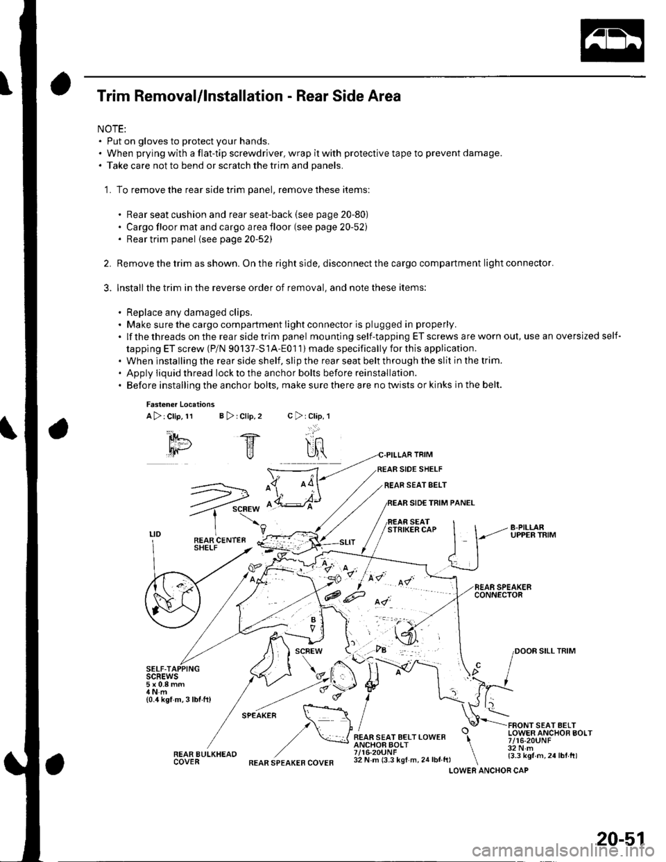
Trim Removal/lnstallation - Rear Side Area
NOTE:. Put on gloves to protect your hands.. When prying with a flat-tip screwdriver, wrap it with protective tape to prevent damage.. Take care not to bend or scratch the trim and panels.
'1. To remove the rear side trim panel, remove these items:
. Rear seat cushion and rear seat-back (see page 20-80). Cargo floor mat and cargo area floor (see page 20-52). Rear trim panel {see page20-52)
Remove the trim as shown. On the right side, disconnect the cargo compartment light connector.
Installthe trim in the reverse order of removal, and note these items:
. Replace any damaged clips.. Make sure the cargo compartment light connector is plugged in properly.
.lfthethreadsontherearsidetrimpanel mounting self-tapping ET screws are worn out, use an oversized self-
tapping ET screw (P/N 90137-S1A-Eo1 1) made specifically for this application.. When installing the rear side shelf, slip the rear seat belt through the slit in the trim.' Apply iiquid thread lockto the anchor bolts before reinstallation.. Before installing the anchor bolts, make sure there are no twists or kinks in the belt.
2.
3.
Fasten€r Locations
A>:Clip,11 B > rClip,2
SELF-TAIscREws5x0.8mm
{0.4 kgf m,3lbf.ft)
REAR BULKHEAOCOVER
TRIM
SIDE SHELF
REAR SEAT SELT
SIDE TRIM PANEL
SEATSTRIKER CAP
FRONT SEAT AELTLOWER ANCHOR BOLT7/16-20UNF32 N.m{3.3 kgf m,24lbt.tt)
c>rClap,l
-..:.:'
SILL TRIM
.F.-*-.n. \::: :\,/ I
,/ \*JREAR SEAT BELT LOWER \ANCHOF BOLT \7/16-20UNF \32 N m (3.3 kgf m, 24 lbf ft, \LOWERREAR SPEAKER COVERANCHOR CAP
20-51
Page 708 of 1139
Interior Trim
Headliner RemovaUlnstallation
NOTE:. When prying with a flat-tip screwdriver, wrap itwith
protective tape to prevent damage.. Take care not to bend and scratch the headliner.. Be careful not to damage the dashboard and other
interior trim.
1. Remove these items:
. A-pillar trim, both sides (see page 20-50). B-pillar uppertrim, both sides (see page 20-50). Hatch weatherstrip, as necessary {see page 20-
92\. C-pillar trim, both sides (see page 20-51). Moonroof switch (see page 22-'112). Spotlights (see page 22-961. Ceiling light (see page 22-96)
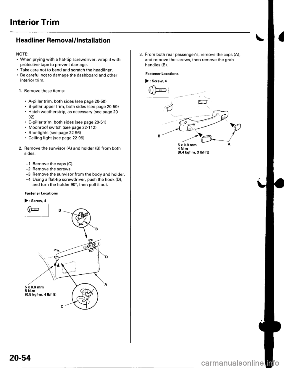
Remove the sunvisor {A) and holder {B) from both
srdes.
-1 Remove the caps {C).-2 Remove the screws.-3 Remove the sunvisor from the body and holder.-4 Using a flat-tip screwdriver, push the hook (D),
and turn the holder 90'. then pull it out.
Fastener Locations
> : Screw, 4
r(\'-r)*
5x0.8mm5 N.m{0.5 kst m.4lbf ft}
20-54
3. From both rear passenger's, remove the caps (A),
and remove the screws, then remove the grab
handles (B).
Fastener Locations
> : Screw, 4
t , t;---iJ
)e
5x0.8mm4 N.m{0.4 kgf.m, 3 lbf.ft}
Page 721 of 1139
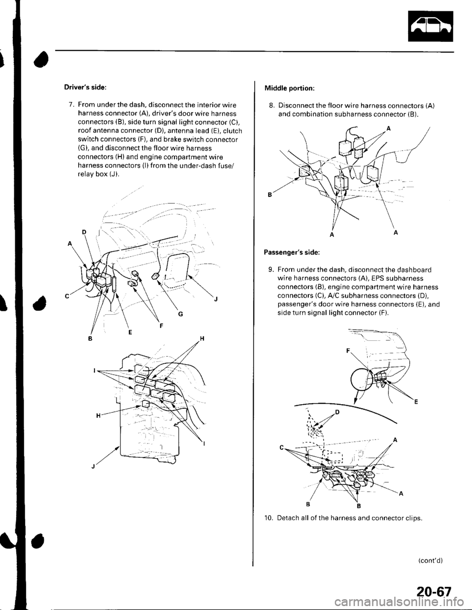
Driver's side:
7. From under the dash, disconnect the interior wire
harness connector (A), driver's door wire harness
connectors (B), side turn signal light connector (C).
roof antenna connector (D), antenna lead (E). clutch
switch connectors (F), and brake switch connector(G), and disconnect the floor wire harness
connectors (H) and engine compartment wire
harness connectors (l)from the under-dash fuse/
relav box (J).
Middle portion:
8. Disconnect the floor wire harness connectors (A)
and combination subharness connector (B).
Passenger's side:
9. From under the dash, disconnect the dashboard
wire harness connectors (A), EPS subharness
connectors (B), engine compartment wire harness
connectors (C), A,/C subharness connectors (D),
passenger's door wire harness connectors {E), and
side turn signal light connector (F).
10. Detach all of the harness and connector clips.
(cont'd)
20-67
Page 739 of 1139
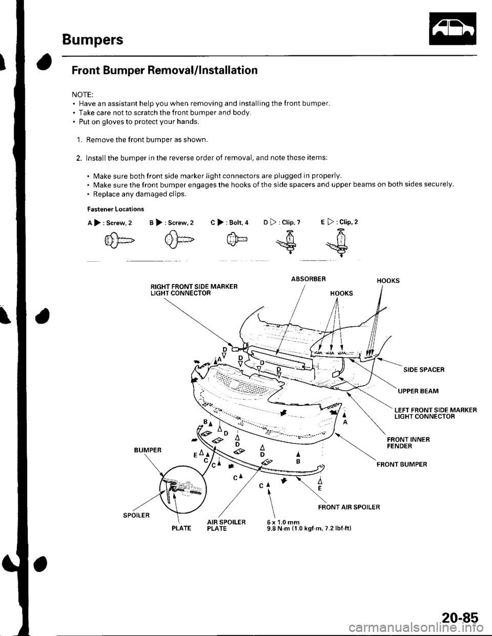
Bumpers
Front Bumper RemovaUlnstallation
NOTE:. Have an assistant help you when removing and installing the front bumper.. Take care not to scratch the front bumper and body.. Put on gloves to protect your hands.
'L Remove the front bumper as shown.
2. Installthe bumper in the reverse order of removal, and note these items:
. Make sure both front side marker light connectors are plugged in properly.
. Make sure the front bumper engages the hooks of the side spacers and upper beams on both sides securely.
. Replace any damaged clips.
Fastener Locations
A),Screw, 2
{D[]
>:Bolt.4 D>:Clip,7 E >:Clip,2
f'h-64k/- *S =$t
B >: Screw,2 C
ABSORBER
SIDE SPACER
UPPER BEAM
LEFT FRONT SIDE MARKERLIGHT CONNECTOR
BUMPER
FRONT INNERFENDER
FEONT BUMPER
AEClI
6x9.8
FRONT AIR SPOILER
AIR SPOILERPLATE1.0 mmN.m (1.0 kgt.m,7.2 lbf.ft)
'*D ;e3
e
ti-\
SPOILER
PLATE
20-85
Page 740 of 1139

Bumpers
Rear Bumper RemovaUlnstallation
NOTE:' Have an assistant help you when removing and installing the rear bumper.. Take care not to scratch the rear bumper and body.. When prying with a flat-tip screwdriver, wrap it with protective tape to prevent damage.. Put on gloves to protect your hands.
L Remove the rear bumDer as shown.
2. Installthe bumper in the reverse order of removal, and note these items:
. Make sure both rear side marker light connectors are plugged in properly.'Makesuretherearbumperengagesthehooksofthesidespacers,sidebrackets,andupperbracketsonboth
sides securely.. Make sure the upper spacers of the rear bumper engage the clips on the body securely.. Replace any damaged clips.
: Screw, 2
XJ
) : Clip,
?ri)
\sI
Fastener Locations
A>:Bolt,2 B
/h-
\-P-
) : Screw, 2
ffiI"-ut ^*
c>
SIDE BRACKET
UPPER SPACER
UPPER BRACKET
\
SIDE SPACER
:r
'-
A
AD
LEFT REAR SIDE MARKERLIGHT CONNECTOR
,6 x 1.0 mm/ 9.eN.n,/ 11.0 kgl m,./ 1.2tbt.ttl
a
\
CAP
REAR BUMPER
20-86
Page 741 of 1139
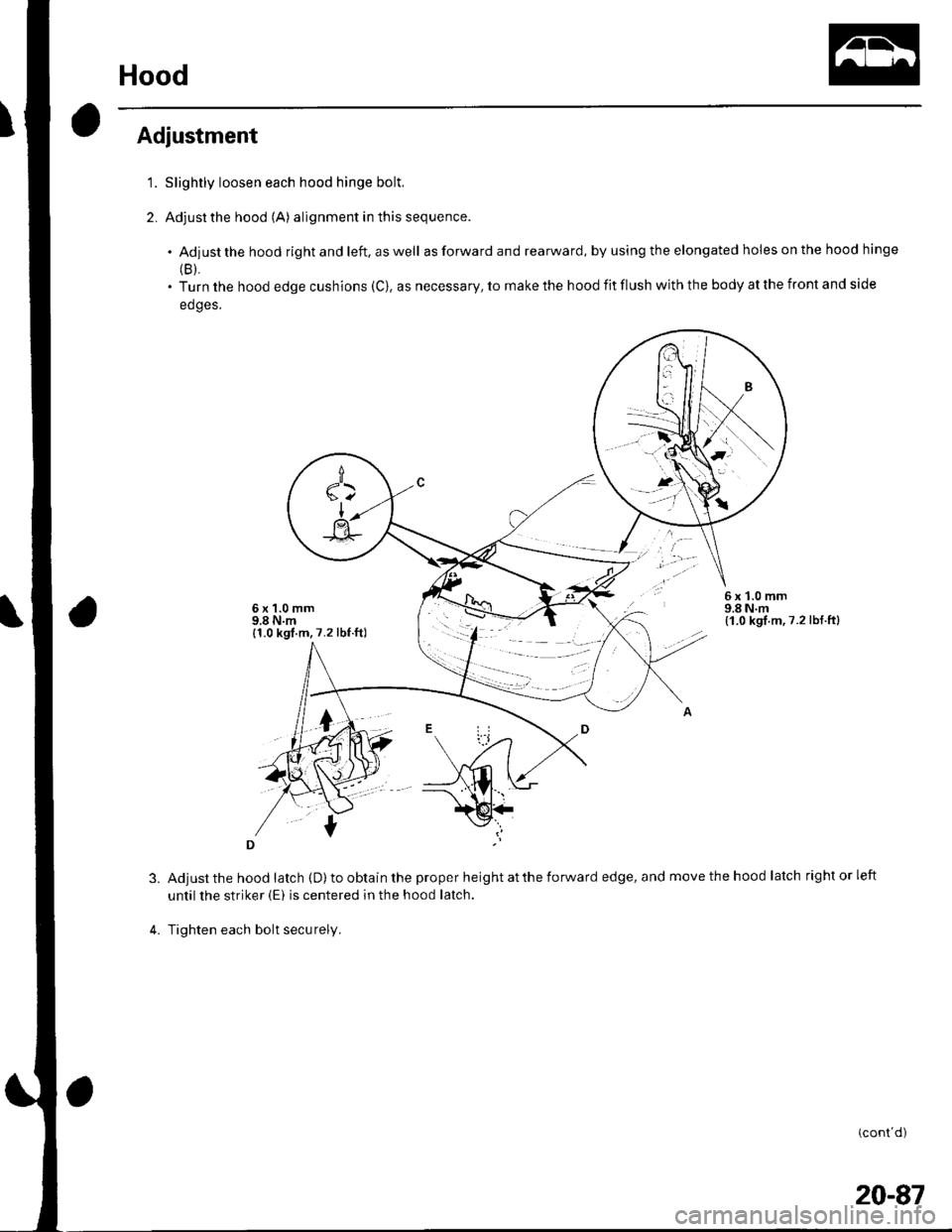
Hood
'1.
2.
Adjustment
3.
Slightly loosen each hood hinge bolt,
Adjust the hood (A) alignment in this sequence.
. Adjustthehoodrightandleft,aswell as forward and rearward, by using the elongated holes on the hood hinge
(B).
. Turn the hood edge cushions (C), as necessary, to make the hood iit flush with the body at the front and side
edges.
6x1.0mm9.8 N.m{1.0 kgf.m,7.2lbf.ft}
Adjust the hood latch (D) to obtain the proper height at the forward edge, and move the hood latch right or left
until the striker (E) is centered in the hood latch.
Tighten each bolt securely.
(cont d)
6x1.0mm9.8 N.m{1.0 kgl.m,7.2 lbf.ftl
20-87