light HONDA CIVIC 2003 7.G Manual PDF
[x] Cancel search | Manufacturer: HONDA, Model Year: 2003, Model line: CIVIC, Model: HONDA CIVIC 2003 7.GPages: 1139, PDF Size: 28.19 MB
Page 744 of 1139
Hatch
Adjustment
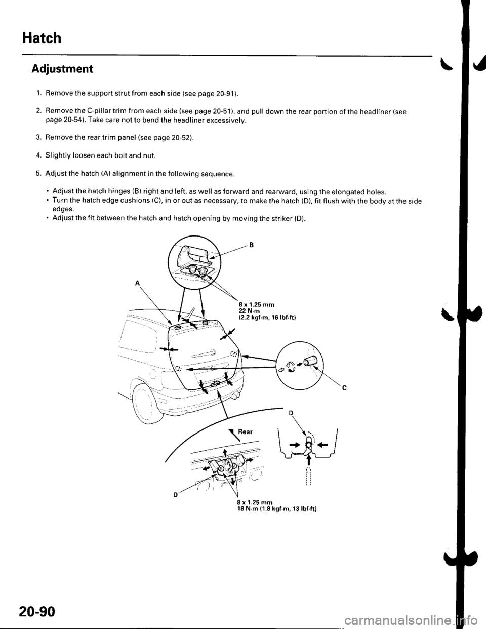
1. Remove the support strut from each side (see page 20-91).
2. RemovetheC-pillartrimfromeachside(seepage20-5'l),andpull downtherearponionoftheheadliner(seepage 20-54). Take care not to bend the headliner excessively.
3. Remove the rear trim panel (see page 20-52).
4, Slightly loosen each bolt and nut.
5. Adjustthe hatch (A) alignment in the following sequence.
. Adjustthe hatch hinges (B) right and left, as well as forward and rearward, using th e elongated holes.'Turnthehatchedgecushions(C),inoroutasnecessary,tomakethehatch(D).fitflushwiththebodyattheside
edges.. Adjust the fit between the hatch and hatch opening by moving the striker (D).
8 x 1.25 mm18 N.m 11.8 kgf.m, 13 lbf.ft)
\
8 x 1.25 mm22 N.m{2.2 kgf.m, 16 lbf.ft}
20-90
Page 747 of 1139
Fuel Fill Door
Adjustment
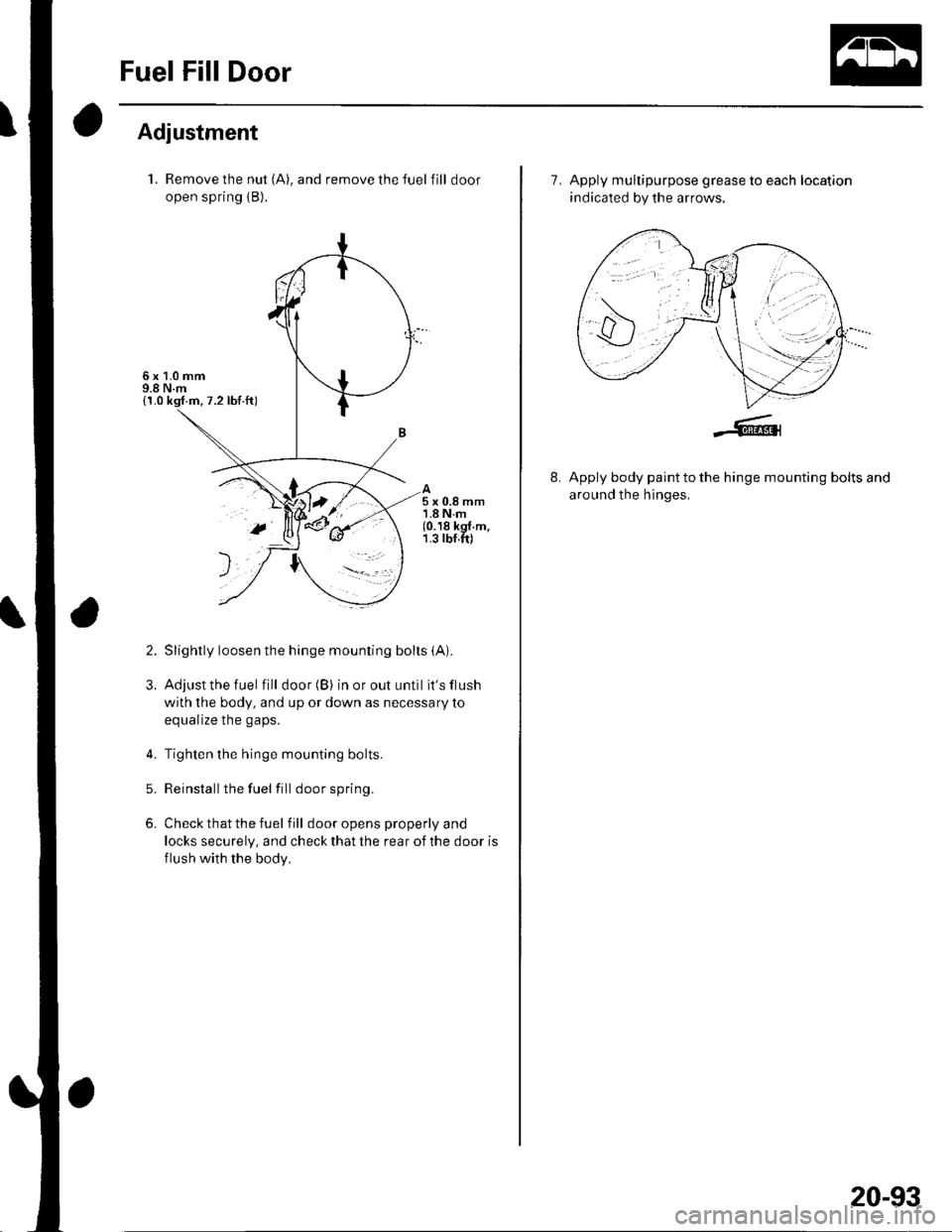
1. Remove the nut (A), and remove the fuel fill door
open spring {B).
Slightly loosen the hinge mounting bolts (A).
Adjust the fuel fill door (B) in or out until it's flush
with the body, and up or down as necessary toa^rr.li7a tha n.nc
Tighten the hinge mounting bolts.
Reinstallthe fuel fill door spring.
Check that the fuel f ill door opens properly and
locks securely, and check that the rear of the door is
flush with the body.
5x0.8mm1.8Nm(0.18 kgf.m,1.3 rbf.ft)
2.
3.
5.
6.
>t=- r'
7. Apply multipurpose grease to each location
indicated by the arrows.
8.Apply body paint to the hinge mounting bolts and
around the hinges,
20-93
Page 753 of 1139
Hatch Spoiler Replacement
NOTE: Put on gloves to protect your hands.
'l. Remove the hatch upper trim (see page 20-53).
2. Remove the high mount brake light (see page 22-
82).
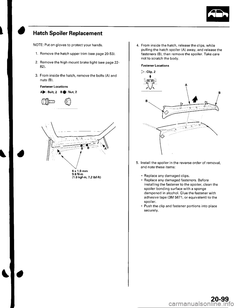
3. From inside the hatch, remove the bolts {A} and
nuts (B).
Fastener Locaiions
A>: Bolt,2 Bar Nut,
fi'f$t-- /,fluLt* v_/
5x1.0mm9.8Nm(1.0 kgf.m.7.2 lbf.ft)
$.A
4. From inside the hatch, release the clips, whilepulling the hatch spoiler (A) away, and release the
fasteners (B), then remove the spoiler. Take care
not to scratch the body.
Fastener Locations
>: Clip. 2
t
Installthe spoiler in the reverse order of removal,
and note these items:
Replace any damaged clips.
Replace any damaged fasteners. Before
installing the fastener to the spoiler, clean the
spoiler bonding surface with a sponge
dampened in alcohol. Glue the fastener with
adhesive tape (3M 5671, or equivalent)to the
spoiler.
Push the clip and fastener portions into place
securely.
5.
20-99
Page 757 of 1139
Front Fender Fairing Replacement
1.Remove the front inner fender as necessary (see
page 20-1O21.
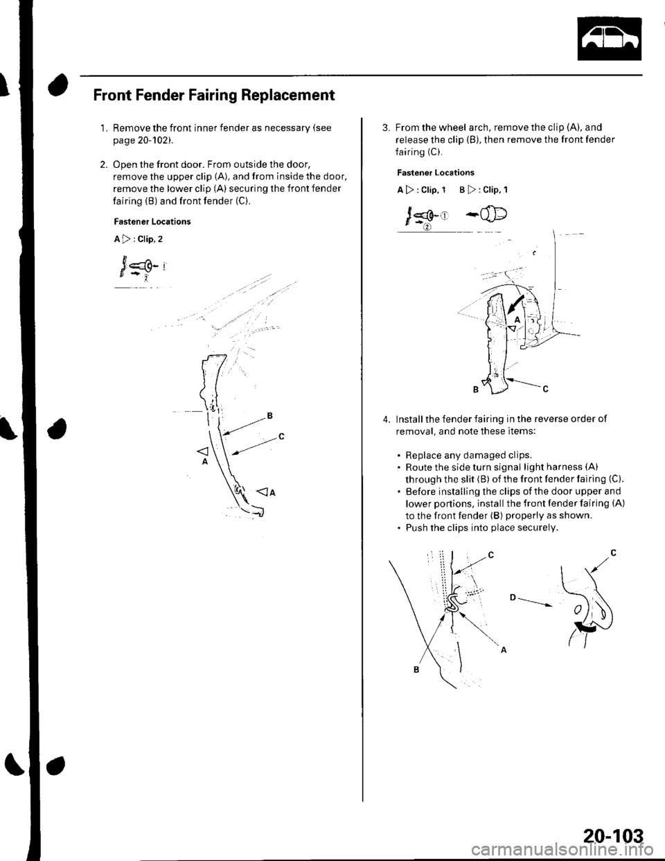
Open the front door. From outside the door,
remove the upper clip (A), and from inside the door,
remove the lower clip (A) securing the front fender
fairing (B) and front fender (C).
Fastener Locations
A>:Clip,2
J
3. From the wheel arch, remove the clip (A), and
release the clip (B), then remove the front fender
fairing (C).
Fastener Locations
A>: Clip, 1 B >: Clip, 1
J*.' -@
Install the fender fairing in the reverse order of
removal, and note these items:
. Replace any damaged clips.. Route the side turn signal lightharness(A)
through the slit (B) of the front fender fairing (C).
. Before installing the clips ofthe door upper and
lower ponions, install the front fender fairing (A)
to the front fender (B) properly as shown.. Push the clips into place securely.
o --____--
4.
20-103
Page 783 of 1139
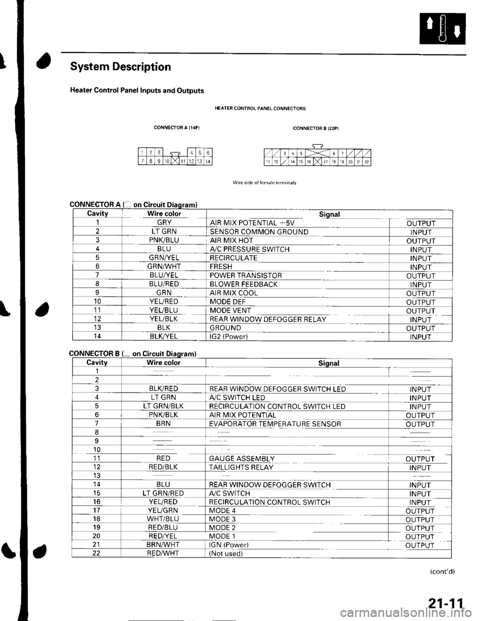
System Description
Heater Control Panel Inputs and Outputs
CONNECTOR A {r/rP)
CONNECTOR
CONNECTOR
HEATER CONTFOL PANEL CONNECIORS
CONNECTOR B (22P)
W re s de oitema eterm nals
Cavity Wire color_| \ln YAIR MIX POTENTIAL +5V
Sional
OUTPUT2LT GRNSENSOR COMMON GROUNDINPUT3PNK/BLUAIR MIX HOTOUTPUTBLUA,/C PRESSURE SWITCHINPUT5GRNA/ELRECIRCULATEINPUT6GRNA/VHTFRESHINPUT7BLUI/ELPOWER TRANSISTOROUTPUT8BLU/REDBLOWER FEEDBACKINPUTIGRNAIR MIX COOLOUTPUT10YEL/REDMODE DEFOUTPUT11. YEVBTU
YEL/BLK
MODE VENT
REAR WINDOW DEFOGGER RELAY
OUTPUT
INPUTBLKGROUNDOUTPUT14B LK/YELlG2 (Power)INPUT
Bon
CavityWire colorSiqnal1--T
2
3BLIVREDREAR WINDOW DEFOGGER SWITCH LEDINPUT
4LT GRNA./C SWITCH LEDINPUT
5LT GRN/BLKRECIRCULATION CONTROL SWITCH LEDINPUT
6PNVBLKAIR MIX POTENTIALOUTPUT
7BRNEVAPORATOR TEIMPERATURE SENSOROUTPUT
8
9
10
GAUGE ASSEMBLYal' 'TDr ri11RED
RED/BLKTAILLIGHTS RELAYINPUT
14BLUREAR WINDOW DEFOGGER SWITCHINPUTicLT GRN/REDA/C SWITCHINPUT16YEVREDRECIRCULATION CONTROL SWITCHINPUT17YEUGRNMODE 4OUTPUT18WHT/BLUMODE 3OUTPUT19RED/BLUMODE 2OUTPUT20RED/YELMODE 1OUTPUTBRN^,^/HTIGN (PowedOUTPUT22R E DA/r'HT(Not used)
(cont'd)
21-11
Page 829 of 1139
Heating and Air Conditioning
A/C System Tests (cont'd)
1.
Performance Test
Air conditioning refrigerant or lubricant vapor
can irritate your eyes, nose, or throar.
Be carefulwhen connecting service equipment.
Do not breathe refrigerant or vapor.
The performance test will help determine if the air
conditioner system is operating within specifications.
Use only service equipment that is U.L.-listed and is
cenified to meet the requirements of SAE J2210 toremove HFC-134a (R-134alfrom the air conditioning
system.
lf accidental system discharge occurs, ventilate the
work area before resuming service
R-134a service equipment or vehicle air conditioning
systems should not be pressure tested or leak testedwith compressed air.
Additional health and safety information may be
obtained from the refrigerant and lubricant
manufacturers.
Connect a R-134a refrigerant recover/recycling/
charging station to the high-pressure service port
and the low-pressure service port, following the
equipment manufacturer's instructions.
Determine the relative humidity and air
Iemperaru re.
' Compressed air mixed with R-134a forms a
combustible vapor.. The vapor can burn or explode causing serious
Injury.. Never use compressed air to pressure test
R-134a service equipment or vehicle air
conditioning systems.
21-58
4.
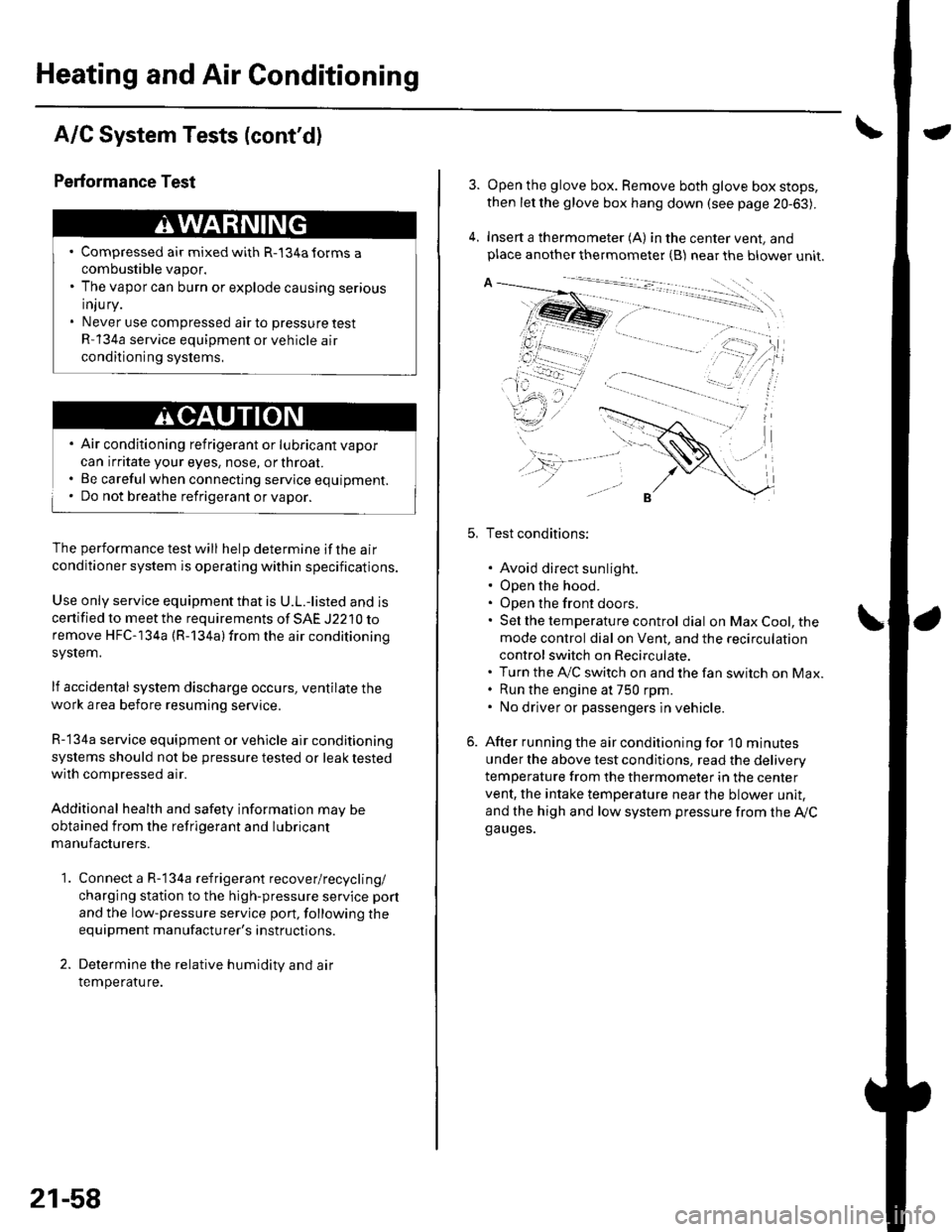
Open the glove box. Remove both glove box stops,
then let the glove box hang down (see page 20-63).
Insert a thermometer (A) in the center vent, andplace another thermometer {B) near the blower unit.
Test conditions:
. Avoid direct sunlight.. Open the hood.. Open the front doors.. Sel the temperature control dial on Max Cool, the
mode control dial on Vent, and the recirculation
control switch on Recirculate.. Turn the A,/C switch on and the fan switch on Max.. Run the engine at 750 rpm.. No driver or passengers in vehicle.
After running the air conditioning for I0 minutes
under the above test conditjons, read the delivery
temperature from the thermometer in the center
vent, the intake temperature near the blower unit,
and the high and low system pressure from the Ay'Cga uges.
Page 831 of 1139
\Body Electrical
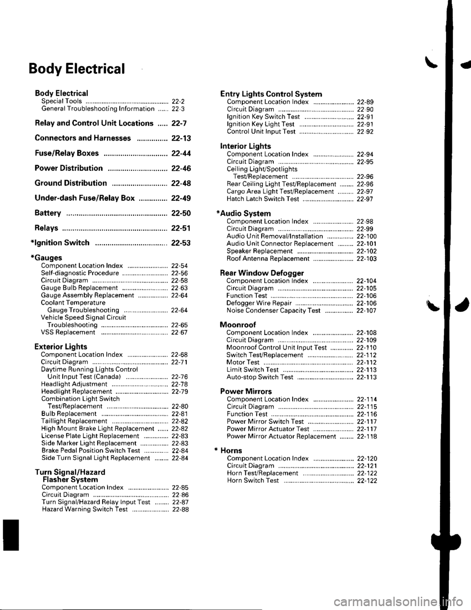
Body ElectricalSpecialToolsGeneral Troubleshooting tntorrnaiion.'......
Relay and Control Unit Locations .....
Connectors and Harnesses
Fuse/Relay Boxes ...............................
Power Distribution .............................
Ground Distribution ...........................
Under-dash Fuse/Relay Box ..............
Battery ..............
Relays ................
*lgnition Switch ..............
*Gauges
Component Location Index .......................Self-diagnostic Procedure ..........................Circuit DiagramGauge Bulb Replacement ..........................Gauge Assembly ReplacementCoolant Temperature
Gauge Troubleshooting .... ....................Vehicle Speed Signal CircuitTroubleshootingVSS Replacement
Exterior LightsComponent Location Index .......................Circuit DiagramDaytime Running Lights ControiUnit Input Test (Canada) ........................Headlight Ad,ustment .................. .. .....Headlighr Replacement ..............................Combination Light SwitchTest/ReplacementBulb ReplacementTaillight Replacement ..........................High Mount Brake Light Replacement ......License Plate Light Replacement ..............Side Marker Light Replacement ................Brake Pedal Position Switch Test ..............Side Turn Signal Light Replacement ........
Turn Signal/HazardFlasher SystemComponent Location Index .......................Circuit DiagramTurn Signal/Hazard Relay lnputTest ........Hazard Warning Switch Test
22,3
22-7
22-13
22-44
22-46
22-4A
22-49
22-50
22-51
22-53
22-5422-5622-5422 6322-64
22-64
22-6522 61
22-6822--71
22-7 622-7422-79
22-AO22-4122-8222-4222-4322-4322-4422-84
22-8�522 A622-8722-88
22-10422-105
22-10622-107
Entry Lights control systemComponent Location Index ....................... 22-89Circuit Diagram ......... 22 90lgnition Key Switch Test .....................,...... 22-9'llgnition Key Light Test ............................... 22-91Control Unit Input Test ..........,.................... 22 92
Interior LightsComponent Location Index ....................... 22-94Circuit Diagram ......... 22-95Ceiling LighVSpotlightsTesVReplacement ................................... 22-96Rear Ceiling Light TesVReplacem ent ........ 22-96Cargo Area Light Test/Replacem ent ......... 22-97Hatch Latch Switch Test ..,..,....................... 22-97
*Audio SystemComponent Location Index ....................... 22-98Circuit Diagram ......... 22,99Audio Unit Removal/lnstallation ............... 22-1OOAudio Unit Connector Replacement ......... 22-101Speaker Replacement ................................ 22-102Roof Antenna Rep1acement ....................-.. 22-103
Rear Window DefoggerComponent Location Index ...........Circuit Diasram .. ....... .. ..... ....... ...:::::.::.::.Function TestDefogger Wire Repair .................................Noise Condenser CapacityTest ................
MoonroofComponent Location Index ....................... 22-1OBCircuit Diagram ......... 22-109Moonroof Control Unit Input Test ............. 22-'l10Switch TesVReplacement ........,.....,........... 22-1 12Motor Test ................. 22-112Limit Swilch Test ...... 22-'l'13Auto-stop Switch Test ................................ 22-1 13
Power MirrorsComponent Location Index ....................... 22-114Circuit Diagram ......... 22-115Function Test ............. 22-116Power Mirror Switch Test .......................... 22-ll7Power Mirror Actuator Test ....................... 22-117Power Mirror Actuator Replacement ........ 22-11A
* HornsComponent Location Index ....................... 22-120Circuit Diagram ......... 22-121Horn TesVReplacement ...........................-. 22-122Horn Switch Test .,.... 22-122
\
Page 837 of 1139
Body Electrical
General Troubleshooting Information (cont'dl
Five-step Troubleshooting
'1. Verify The Complaint
Turn on allthe components in the problem circuit
to verify the customer complaint. Note the
symptoms. Do not begin disassembly or testing
until you have narrowed down the problem area.
2. Analyze The Schematic
Look up the schematic for the problem circuit.
Determine how the circuit is supposed to work by
tracing the current paths from the power feed
through the circuit components to ground. lf
several circuits fail at the same time, the fuse or
ground is a Iikely cause.
Based on the symptoms and your understanding of
the circuit operation, identify one or more possible
causes of the problem.
3. lsolate The Problem By Testing The Circuit
Make circuit tests to check the diagnosis you made
in step 2. Keep in mind that a logical, simple
procedure is the key to efficient troubleshooting.
Test for the most likely cause of failure first, Try to
make tests at points that are easily accessible.
4. Fix The Problem
Once the specific problem is identified. make the
repair. Be sure to use proper tools and safe
proceoures.
5. Make Sure The Circuit Works
Turn on all components in the repaired circuit in all
modes to make sure you've fixed the entire
problem. lf the problem was a blown fuse, be sure
to test all of the circuits on the fuse. Make sure no
new problems turn up and the original problem
does not recur.
22-6
Wire Color Codes
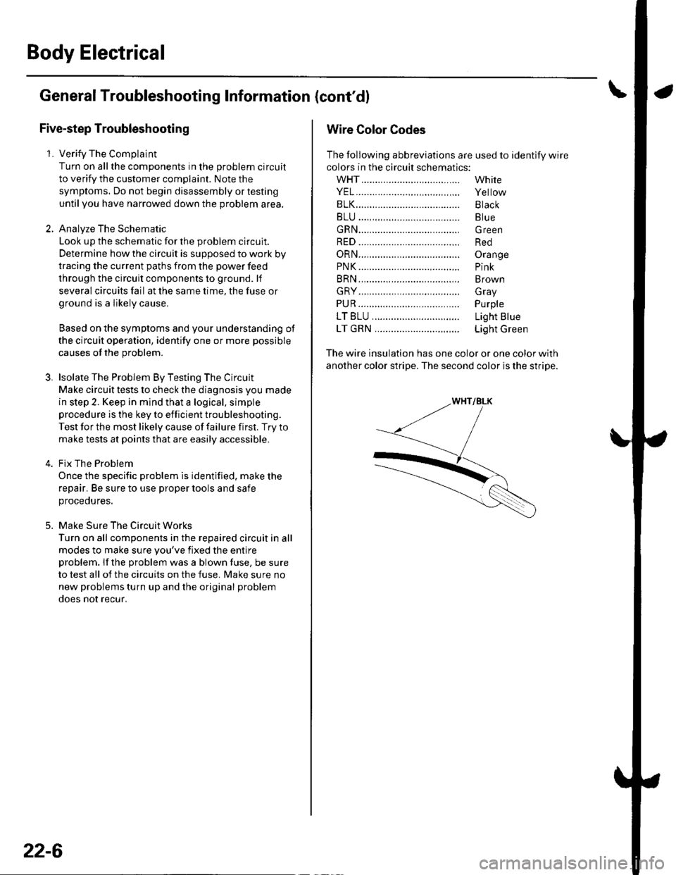
The following abbreviations are used to identify wire
colors in the circuit schematics:
wHT....................,.,.............
YEL......................,,.......,......
B1K......................................
BLU ....,................................
GRN.....................................
RED ....................................,
oRN.....................................
PNK..........................,..........
BRN.....................................
GRY....................................,
PUR.....................................
1T81U..........................,.....
1TGRN...........................,...
White
Yellow
Black
Blue
Green
Red
Orange
Pink
Brown
Gray
Purple
Light Blue
Light Green
The wire insulation has one color or one color with
another color stripe. The second color is the stripe.
Page 839 of 1139
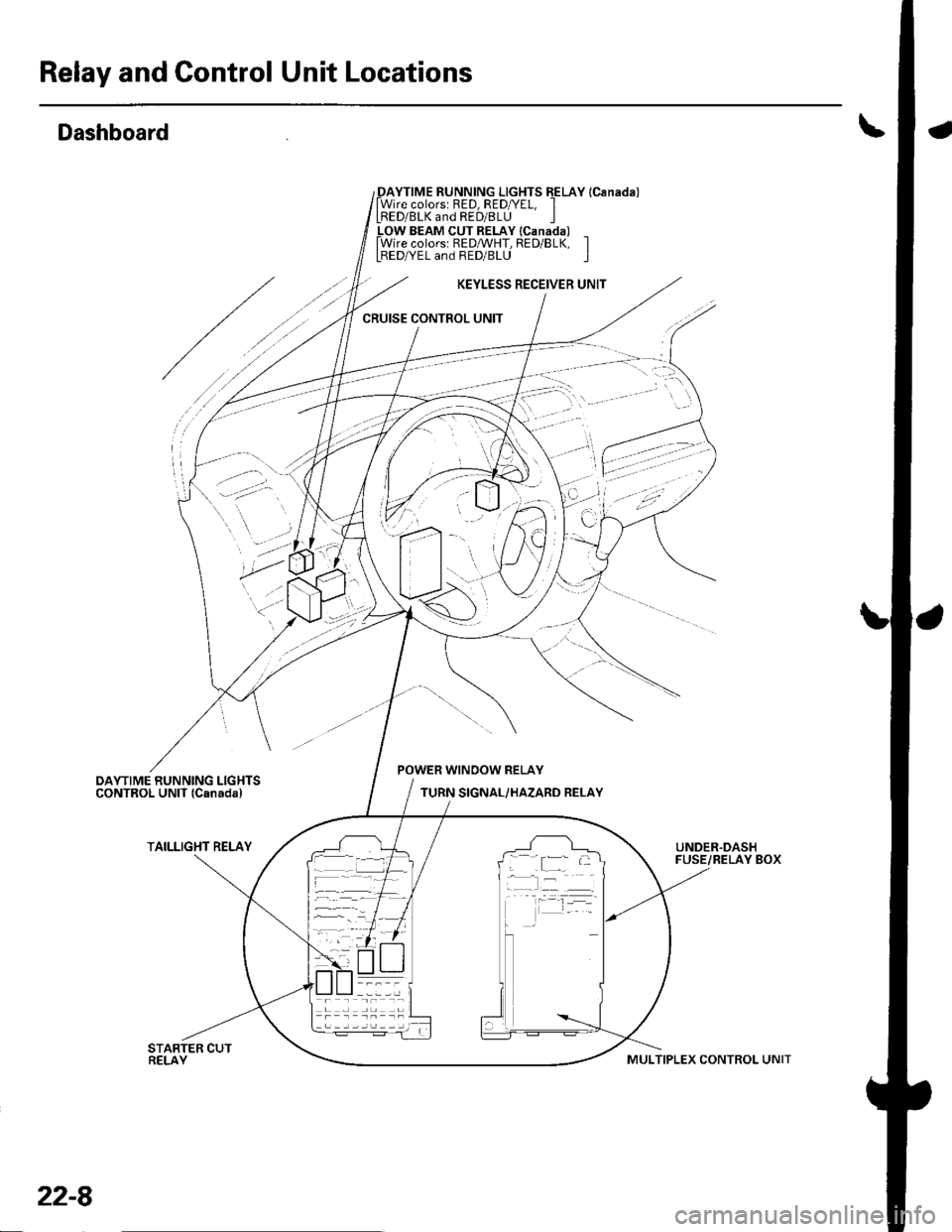
Relay and Gontrol Unit Locations
Dashboard
_DAYTIME RUNNING LIGHTS EELAY lCanada)lWire colorsr RED, RED/YEL, ILRED/BLK and RED/8LU I_LOW BEAM CUT RELAY lcanada) _lWire colors: REDMHT, RED/BLK, ILBEDA/EL and RED/BLU I
KEYLESS RECEIVER UNIT
CRUISE CONTROL UNIT
'
'-.:- ':
..? ;,
POWER WINOOW RELAY
TURN SIGNAL/HAZARD RELAY
TAILLIGHT RELAYUNDER.DASHFUSE/RELAY BOX; .[:_- -
-l:r --
22-8
MULTIPLEX CONTROL UNIT
Page 844 of 1139
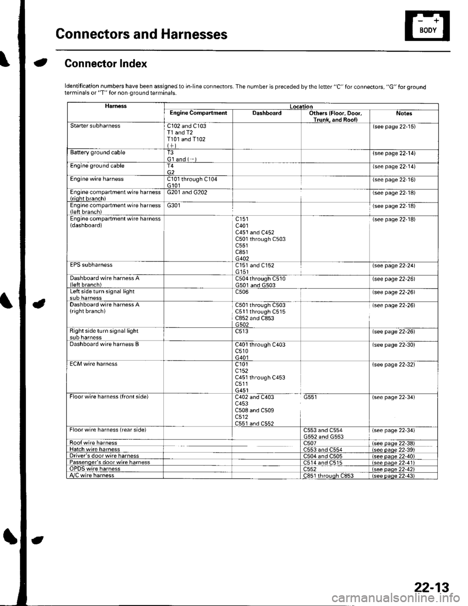
Gonnectors and Harnesses
aGonnector Index
ldentification numbers have been assigned to in-line connectors. The number is preceded by the letter "C" for connectors, "G" for groundterminals or "T" for non ground terminals.
HamessLocationEngine CompartmentDashboardOthers {Floor, Door,Trunk. and Roo{lNot€s
Starter subharnessC102 and C103T1 and T2T101 and T102
(see page 22-15)
Battery ground cableT3G'l and ( -{see page 22-l!)
Engine ground cableT4{see page 22-14)
Engine wire harnessCl0l through C104G 101(see page 22 16)
Engine compartment wire harness{rioht branchiG201 and G202(see page 22 18)
Engine compartment wire harness(left brench)G301(see page 22 18)
Engine compartment wire harness(dashboard)c401C451 and C452C501 through C503c551c851G402
(see page 22-18)
EPS subharnessC151 and C152G'151\see page 22 241
Dashboard wire harness Alleft branch)C504 through C510G501 and G503(see page 22-26)
Left side turn signal lightc506(see page 22-26)
Dashboard wire harness A(right branch)C50l through C503C5ll through C515C852 and C853G502
(see page 22-26)
Right side turn si9nal lightsub harnesslsee page 22-26)
Dashboard wire harness BC40l through C403c510G40l
(see page 22-30)
ECM wire harnessc101cl52C451 through C453c511G451
{see page 22-32}
Floorwire harness (front side)C402 and C403 G551c453C508 and C509c512C551 an.l C55?
(see page 22'34)
Floor wire harness (rear side)C553 and C554(see page 22-34)
Roo{ wire harnessc507(see paqe 22-38)Hatch wire harnessC553 and C554(s6e paqe 22'39)Driver's door wire harnessC504 and C505(see paqe 22-40)Passenqer's door wi.e harness514 and C515(see oaoe 22-41Te harness)552(see oaqe 22-42i/C wire harnessc851 rhrouoh c853(see paqe 22.43i
22-13