ECT sensor HONDA CIVIC 2003 7.G Manual PDF
[x] Cancel search | Manufacturer: HONDA, Model Year: 2003, Model line: CIVIC, Model: HONDA CIVIC 2003 7.GPages: 1139, PDF Size: 28.19 MB
Page 304 of 1139
MIL Circuit Troubleshooting
1. Connect an OBD ll scan tool/Honda PGM Tester
(see page 11-3).
2. Turn the ignition switch ON (ll) and read the OBD ll
scan tool/Honda PGM Tester.
Does the OBD ll scan tool/Honda PGM Tester
communicate with the ECM?
YES Go to step 3.
NO Go to troubleshooting " DLC Circuit
Troubleshooting" (see page 11-109).
3. Check the OBD ll scan tool/Honda PGM Testerfor
DTCs.
Are any DTCs ind icated?
YES Go to the DTC Troubleshooting Index.
NO-Go to step 4.
4. Turn the ignition switch OFF.
5. Turn the ignition switch ON (ll)and watch the
lMalfunction Indicator Lamp (MlL).
Does the MIL come on and stay on for more than
20 seconds aftet turning the ignition switch
oN (tr)?
YES lf the MIL always comes on and stays on, go
to step 76. But if the lMlL sometimes works
normally, first check for these problems.
. An intermittent short in the wire between the
ECIM (E29) and the data link connector (DLC).
. An intermittent short in the wire between the
ECM (E31) and the gauge assembly.
NO lf the MIL is always off, go to step 6. But if the
lvllL sometimes works normally, first check for
these problems.
. A loose No. 10 METER (7.5A) fuse in the under
dash fuse/relay box.. A loose No. 20 lG (40A) (Canada: 50A)Iuse in the
under-hood fuse/relay box.. A ioose No. 6 ECU (ECM) (15A) fuse in the under-
hood fuse/relay box.
. A loose No. 17 FUEL PUMP (15A)fuse in the
under-dash fuse/relay box.. A poor connection at ECM terminal E31.. An intermittent open in the GRN/ORN wire
between the ECM (E31) and the gauge assembly.. An intermittent short in the wire between the
ECM (A21) and the manifold absolute pressure
(MAP) sensor.. An intermittent short in the wire between the
ECI\4 (A20) and the throttle posilion (TPi sensor.. An intermittent short in the wire between the
ECM (E5) and the fuel tank pressure (FTP) sensor.
6. Turn the ignition switch OFF.
7. Turn the ignition switch ON (ll).
ls the low oil pressure light on?
YES Go to step 10.
NO-Go to step 8.
8. Inspectthe No. 10 l\4ETER (7.5A)fuse inthe under-
dash fuse/relay box.
ls the luse OK?
YES Go to step L
NO Repair shon in the wire between No. 10
METER (7.5A)fuse and the gauge assembly. Also
replacethe No. 10 METER {7.5A) fuse.l
9. Inspect the No. 20 lG1 (40A) (Canada: 50A) fuse in
the under-hood fuse/relay box.
ls the f use OK?
YES Repair open in the wire between the No. 20
lG (40A) {Canadar 50A)fuse and the gauge
assembly. lf the wire is OK, test the ignition switch
{see page 22 53).
NO Repair short in the wire between No. 20 lG
(40A) lCanada: 50A)fuse and the under'dash fusel
relay box. Also replace the No.20 lG (40Ai
(Canada: 50A) fuse.I
(conr'd)
11-97
Page 306 of 1139
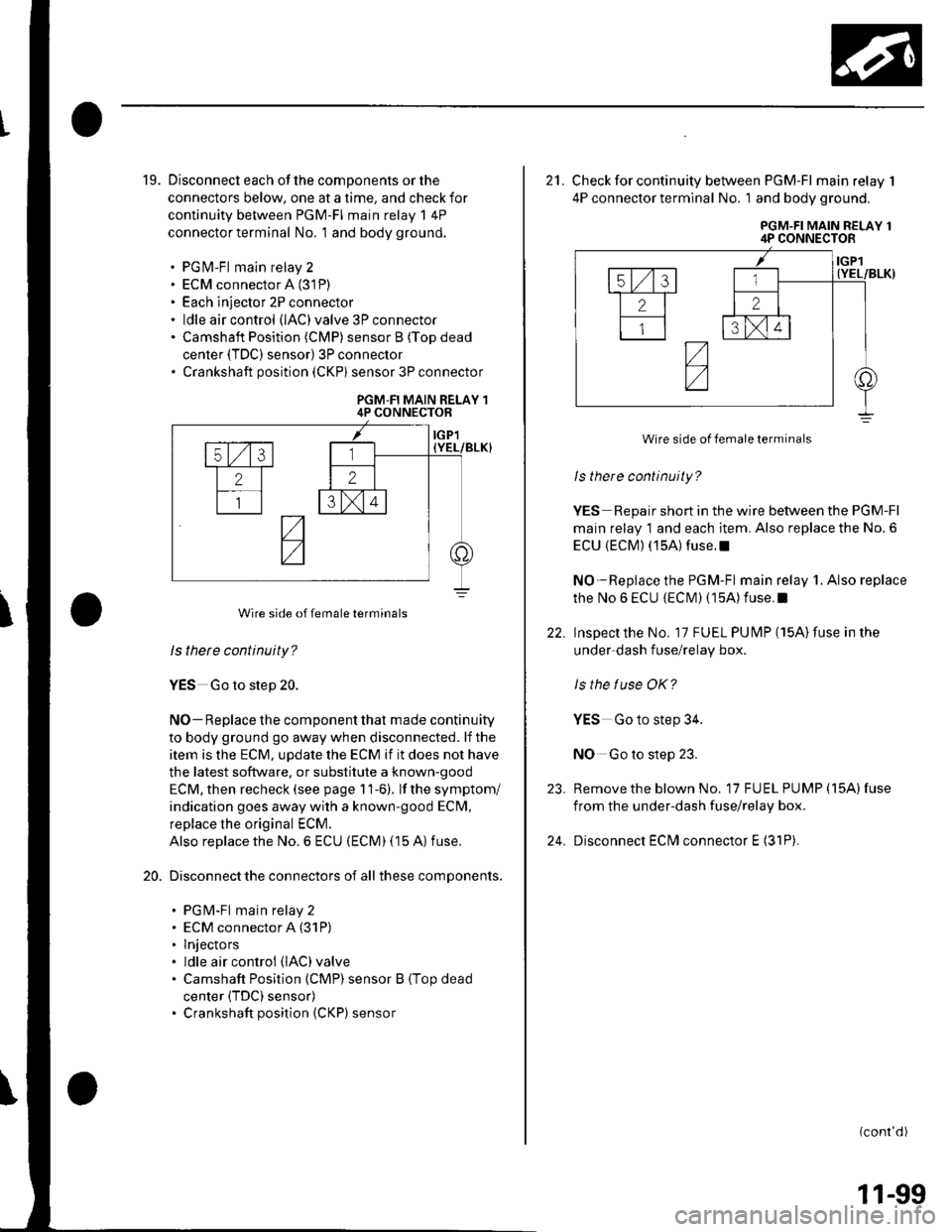
19. Disconnect each of the components or the
connectors below, one at a time, and check for
continuity between PGM-FI main relay 1 4P
connector terminal No. 1 and body ground.
. PGfvl-Fl main relay 2. ECM connector A (31P)
. Each injector 2P connector. ldle air control (lAC)valve 3P connector. Camshaft Position (CMP) sensor B (Top dead
center (TDC) sensor) 3P connector. Crankshaft position (CKP) sensor 3P connector
PGM-FI MAIN RELAY 14P CONNECTOR
ls thete continuity?
YES Go to step 20.
NO- Replace the component that made continuity
to body ground go away when disconnected. lf the
item is the ECM, update the ECM if it does not have
the latest software. or substitute a known-good
ECM, then recheck (see page 11-6). lf the symptom/
indication goes away with a known'good ECM,
replace the original ECM.
Also replace the No. 6 ECU (ECM) (15 A) fuse,
Disconnect the connectors of all these components.
. PGM-Fl main relay 2. ECM connector A (31P)
. lnjectors. ldle air control (lAC)valve
. Camshaft Position {CMP) sensor B (Top dead
center (TDC) sensor). Crankshaft position (CKP) sensor
20.
Wire side of female terminals
22.
21. Check for continuity between PGM-FI main relay 1
4P connector termlnal No. 1 and body ground.
PGM-FI MAIN RELAY 14P CONNECTOR
ls there continuity?
YES Repair short in the wire between the PGM-Fl
main relay 1 and each item. Also replace the No. 6
ECU {ECM) (15A) fuse.l
NO-Replace the PGM-Fl main relay 1. Also replace
the No 6 ECU {ECIM) (15A) f use. I
Inspectthe No. 17 FUEL PUI\4P (15A)fuse in the
under-dash f use/relay box.
ls the tuse OK?
YES Go to step 34.
NO Go to step 23.
Remove the blown No, 17 FU EL PUMP (15A) fuse
from the under-dash fuse/relay box.
Disconnect ECfvl connector E (31P).
(conr'd)
23.
24.
Wire side of female terminals
11-99
Page 311 of 1139
PGM-FI System
MIL Circuit Troubleshooting (cont'dl
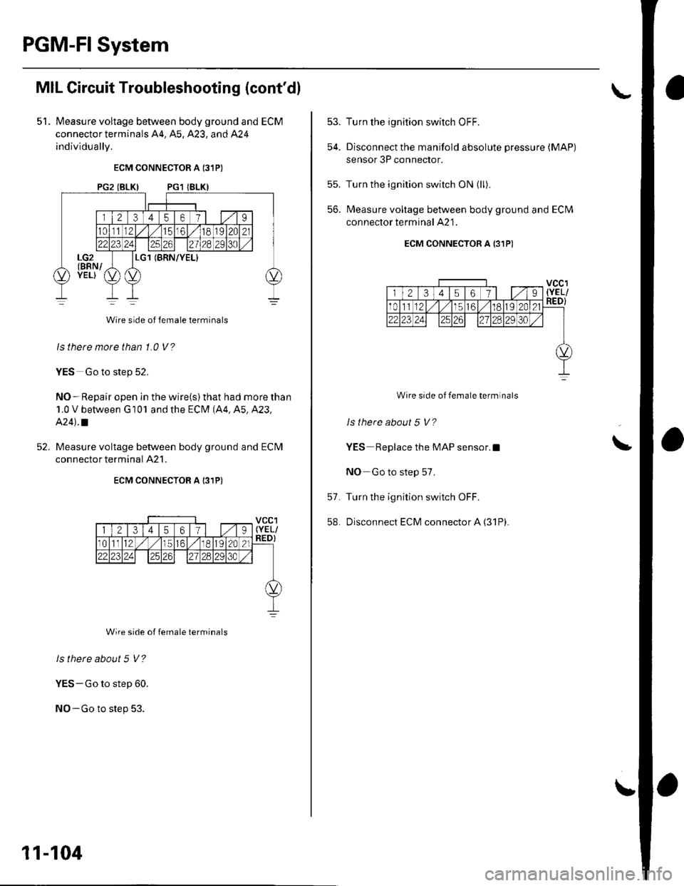
51. Measure voltage between body ground and ECM
connector terminals 44, A5, 423, and 424
individuallv.
ECM CONNECTOR A 131P)
PG2 (BLK) PG1 IBLKI
Wire side of female terminals
ls there morc than 1.0 V ?
YES Go to step 52.
NO-Repair open in the wire(s) that had more than
1.0 V between G 10'l and the ECM (A4, A5, A23,
A24l.a
Measure voltage between body ground and ECM
connector terminal 421.
ECM CONNECTOR A 131P)
Wire side of female terminals
ls there about 5 V?
YES-Go to step 60.
NO-Go to step 53.
11-104
53.
54.
Turn the ignition switch OFF.
Disconnect the manifold absolute pressure (MAP)
sensor 3P connector.
Turn the ignition switch ON (ll).
Measure voltage between body ground and ECM
connector terminal A21.
ECM CONNECTOR A {31P)
Wire side of female terminals
ls there about 5 V?
YES Replace the MAP sensor.l
NO Go to step 57.
Turn the ignition switch OFF.
Disconnect ECM connector A (31P).
55.
56.
\
57.
58.
Page 312 of 1139
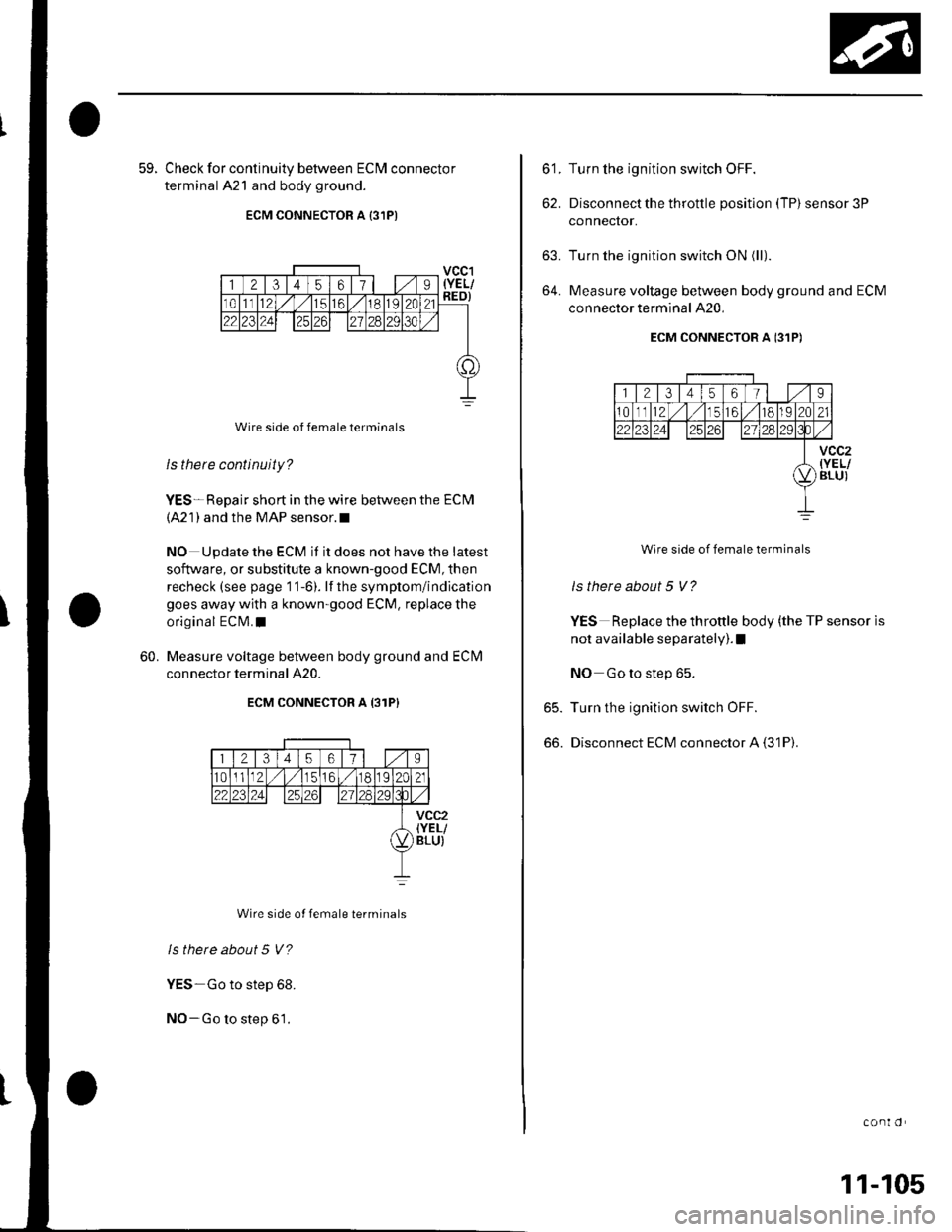
59. Check for continuitv between ECIM connector
terminal 421 and body ground.
ECM CONNECTOR A {3,IPI
Wire side of female terminals
ls there continuity?
YES*Repair short in the wire between the ECM(421) and the MAP sensor.l
NO Update the ECM it it does not have the latest
soflware, or substitute a known-good ECM, then
recheck (see page 1'l-6). lf the symptom/indication
goes away with a known-good ECM, replace the
original ECM.I
Measure voltage between body ground and ECM
connector terminal 420.
ECM CONNECTOR A {3TP}
60.
1121345ot/I
101111256/ 11892t212'231?4?qTln29
vcc2IYEL/BLU)
Wire side ot female terminals
ls there about 5 V?
YES-Go to step 68.
NO-Go to step 61.
t t,
oz,
63.
64.
Turn the ignition switch OFF.
Disconnect the throttle position (TP) sensor 3P
connector.
Turn the ignition switch ON (ll).
Measure voltage between body ground and ECM
connector terminal 420,
ECM CONNECTOR A 131P)
Wire side of female terminals
ls there about 5 V?
YES Replace the thronle body (the TP sensor is
not available separately). I
NO Go to step 65.
Turn the ignition switch oFF.
Disconnect ECM connector A (31P).
65.
66.
conl o
11-105
Page 313 of 1139
PGM-FI System
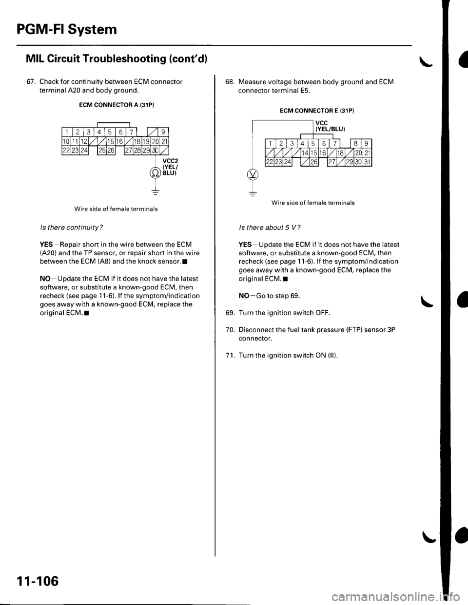
67.
MIL Circuit Troubleshooting (cont'd)
Check for continuity between ECIM connector
terminal A20 and body ground.
ECM CONNECTOR A (31P)
rl2l3145ot/9
10t1121,/ 1,/1516ta,92A21
22 '3241 12526n
o
Wire side of female terminals
ls there continuity?
YES Repair shon in the wire between the ECN4
{A20) and the TP sensor, or repair short in the wire
between the ECM (A8) and the knock sensor. t
NO Update the ECM if it does not have the latest
software. or substitute a known-good ECM, then
recheck (see page l1-6). lf the symptom/indication
goes away with a known-good ECM, replace the
original ECM.t
vcc2{YEL/BLU}
11-106
68. Measure voltage between body ground and ECM
connector terminal E5.
ECM CONNECTOR E (31PI
Is there about 5 V?
YES U pdate the ECM if it does not have the latest
software, or substitute a known-good ECM, then
recheck (see page 11-6). lf the symptom/indication
goes away with a known-good EClvl, replace the
original ECM.t
NO-Go to step 69.
Turn the ignition switch OFF.
Disconnect the fuel tank pressure (FTP) sensor 3P
connector.
Turn the ignition switch ON (ll).
69.
70.
11.
Wire side of female terminals
Page 314 of 1139
13.
74.
75.
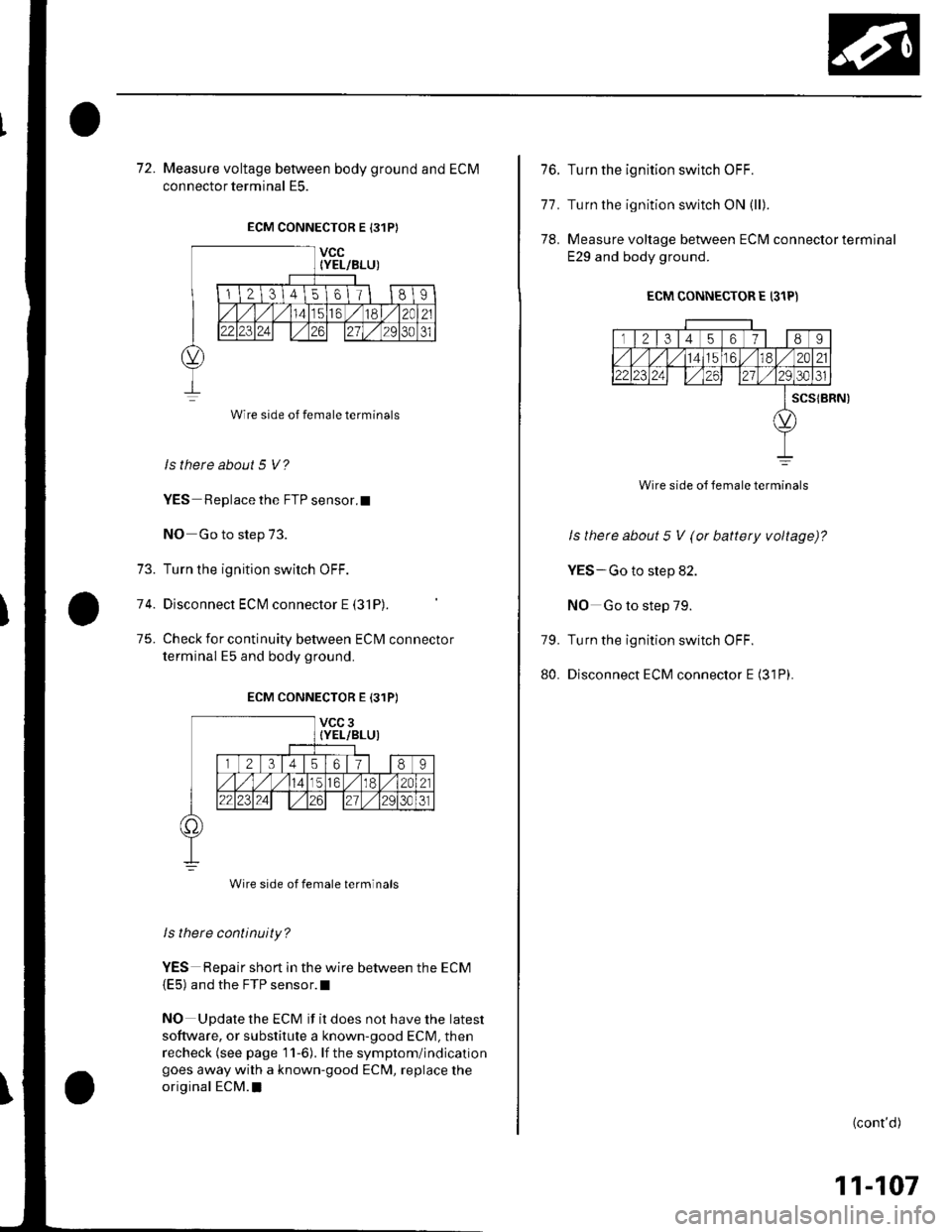
72. Measure voltage between body ground and ECM
connector terminal E5.
ECM CONNECTOR E 131P}
ls there about 5 V?
YES Replace the FTP sensor.t
NO Go to step 73.
Turn the ignition switch OFF.
Disconnect ECM connector E (3'lP).
Check for continuity between ECM connector
terminal E5 and body ground.
ECM CONNECTOR E {31PI
Is there continuity?
YES Repair short in the wire between the ECM(E5) and the FTP sensor.l
NO Update the ECM if it does not have the latest
software, or substitute a known-good ECM, then
recheck (see page 11-6). lf the symptom/indicationgoes away with a known-good ECM, replace the
original ECM.I
Wire side of female terminals
Wire side of female terminals
76.
77.
78.
79.
80.
Turn the ignition switch OFF.
Turn the ignition switch ON (ll).
Measure voltage between ECM connector terminal
E29 and body ground.
ECM CONNECTOR E (31P)
rl2l31456189
,/1,/1141562A212223241 l,/2930
scstBRN)
Wire side of female terminals
ls there about 5 V (or battery voltage)?
YES-Go to step 82.
NO Go to step 79.
Turn the ignition switch OFF.
Disconnect ECM connector E (31P).
(cont'd)
11-107
Page 320 of 1139
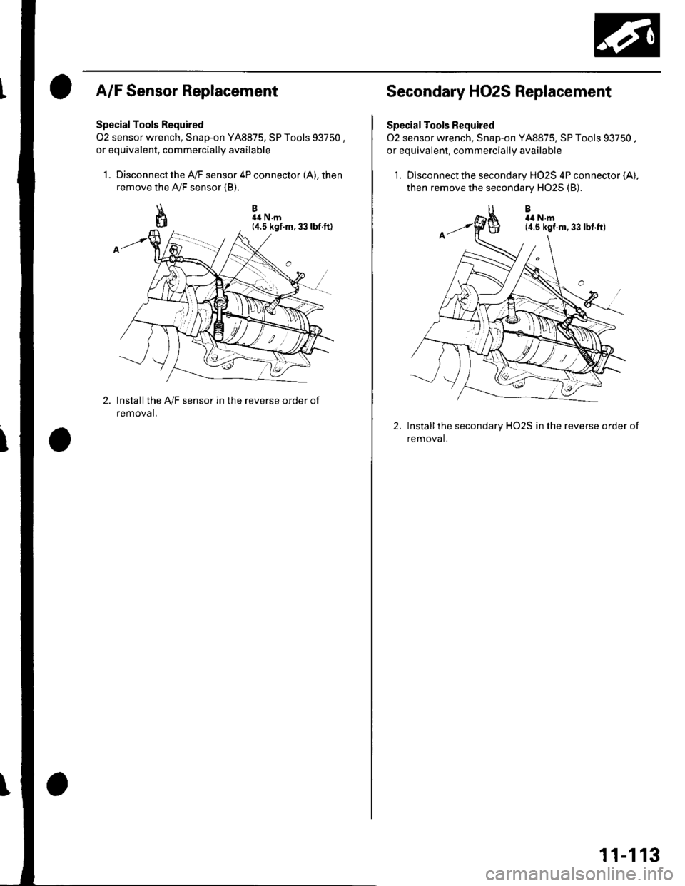
A/F Sensor Replacement
Special Tools Required
O2 sensor wrench, Snap-on YA8875. SP Tools 93750 ,or equivalent, commercially availabre
1. Disconnect the A,/F sensor 4P connector (A), then
remove the A,/F sensor {B).
\I
ffi
B44 N.m
Installthe IVF sensor in the reverse order of
removal.
Secondary HO2S Replacement
Special Tools Fequired
02 sensor wrench, Snap-on YA8875, SP Tools 93750 ,or equivalent, commerciallV available
1. Disconnect the secondary HO2S 4P connector (A),
then remove the secondary H02S (B).
Installthe secondary HO2S in the reverse order of
removal.
2.
11-113
Page 321 of 1139
PGM-Fl System
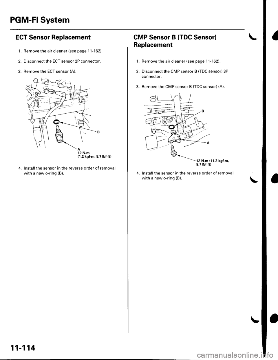
ECT Sensor Replacement
'1. Remove the air cleaner {see page 11-162).
2. Disconnect the ECT sensor 2P connector.
3. Remove the ECT sensor (A).
{1.2 kgt m.8.7 lbt.ft}
reverse order of removallnstallthe sensor in the
with a new o-ring {B).
11-114
CMP Sensor B (TDC Sensorl
't.
2.
Replacement
Remove the air cleaner (see page 11-162).
Disconnect the CN4P sensor B (TDC sensor) 3P
conneclor.
Remove the CMP sensor B (TDC sensor) (A).
----
r, ".- ,',',., *nr...8.7 tbf.ftl
lnstallthe sensor in the reverse order of removal
with a new o-ring {B).
4.
Page 322 of 1139
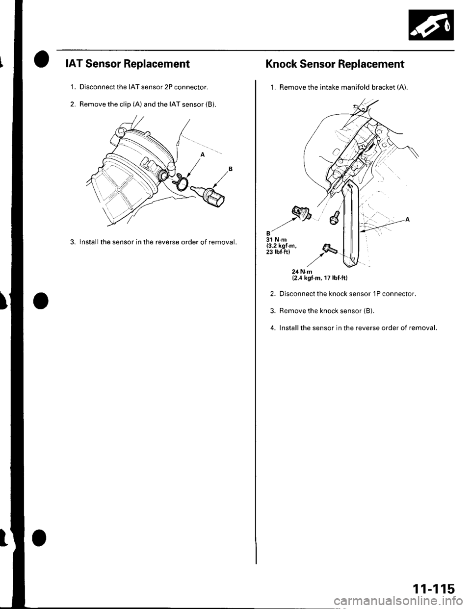
IAT Sensor Replacement
1, Dlsconnect the IAT sensor 2P connector.
2. Remove the clip (A) and the IAT sensor (B).
3. lnstallthe sensor in the reverse order of removal.
Knock Sensor Replacement
1. Remove the intake manifold bracket (A).
2.
3.
4.
24Nm(2.4 kgt.m, 17 lbt.ftl
Disconnect the knock sensor 1P connector.
Remove the knock sensor (B).
Installthe sensor in the reverse order of removal.
11-115
Page 323 of 1139
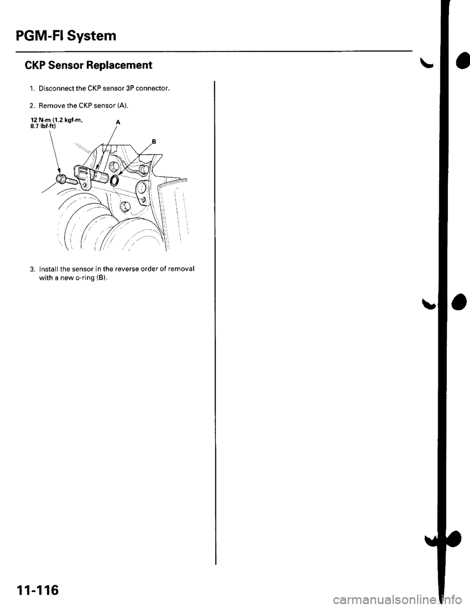
PGM-FI System
GKP Sensor Replacement
1. Disconnect the CKP sensor 3P connector.
2. Remove the CKP sensor {A).
12 N.m (1.2 kgt m.8.7 tbf.ftl
3. lnstall the sensor in the reverse order of removal
with a new o-ring (B).
11-116