Indicator HONDA CIVIC 2003 7.G Workshop Manual
[x] Cancel search | Manufacturer: HONDA, Model Year: 2003, Model line: CIVIC, Model: HONDA CIVIC 2003 7.GPages: 1139, PDF Size: 28.19 MB
Page 25 of 1139
t
v
2-13
o
o
a
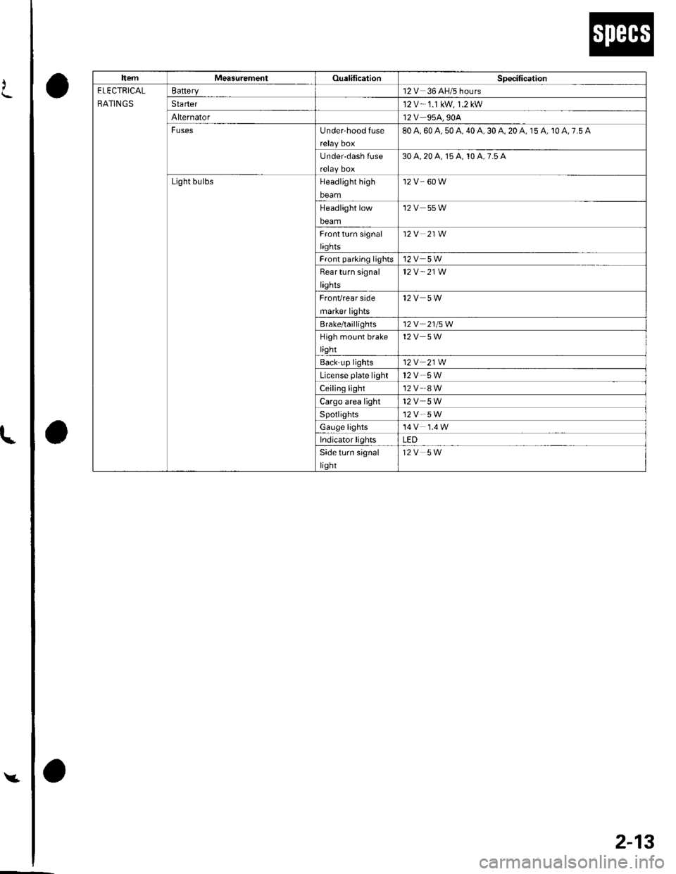
ItemMeasurementOualilicationSpecitication
ELECTRICAL
RATINGS
Battery12V 36 AH/5 hours
Sta rter12 V-.1.1 kW, 1.2 kW
Alternator12V 95A,90A
FusesUnder-hood fuse80 A, 60 A, 50 A, 40 A, 30 A, 20 A, 15 A, 10 A, 7.5 A
Under'dash Iuse30 4,20 a, 15 A, 10 A,7.5 A
Light bulbsHeadlight high
beam
'12 v.' 60 w
Headlight low
beam
12V 55W
Frontturn signal
liqhts
12V 21W
Front parlinq lights12V 5W
Bear turn signal
lights
12V " 21W
FronVrear side
marker lights
12V 5W
Brale/taillighls12V 21/5W
High moLrnt brake
light
12V 5W
Back up lights12V 21W
License plate light12V 5W
Ceiling light'12 v'.8 w
Cargo area light12V 5W
Spotlights12V 5W
Gauge lights
Indicator lightsLED
Side turn signal
light
12V 5W
Page 55 of 1139
Gharging System
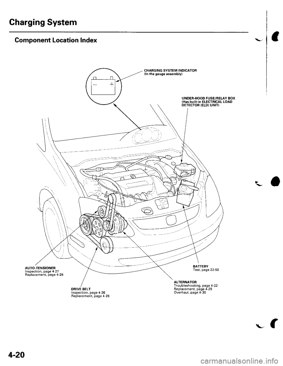
Component Location Index
CHARGING SYSTEM INDICATOR(ln the gauge assembly)
q*o
DRIVE BELTInspection, page 4 26Replacement, page 4 26
BATTERYTest, page 22-50
ALTEBNATORTroubleshooting, page 4-22Replacement, page 4-29Overhaul, page 4-30
4-20
Page 57 of 1139
Gharging System
Charging Circuit Troubleshooting
lf the charging system indicator does not come on or
does not go off, or the battery is dead or low, test these
items in the order listed below:
Battery (see page 22-50)
Charging system indicator
Alternator and regulator circuit
Alternator control system
Charging System Indicator Test
1. Turn the ignition switch ON {ll).
Does the chatging system indicator come on?
YES Go to step 2.
NO Go to step 3.
2. Start the engine.
Does the charging system indicator go off?
YES-Charging system indicator circuit is OK. Go
to the Alternator and Regulator circuit Test. t
NO-Go to step 3.
3. Turn the ignition switch OFF.
4. Troubleshoot the multiplex control system (see
page 22 172).
ls the multiplex control system OK?
YES Go to step 5.
NO Check the multiplex control system as
indicated by the diagnostic trouble code (DTC) (see
step 8 on page 22-172).1
5. Disconnect the engine wire harness 6P connector
from the starter sub harness 6P connector.
4-22
\"4
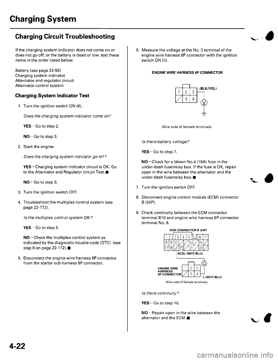
6. Measure the voltage at the No. 3 terminal of the
engine wire harness 6P connector with the ignition
switch ON { ll).
ENGINE WIRE HARNESS 6P CONNECTOR
IBLK/YEL}
Wire side of female terminals
ls there battery voltage?
YES-Go to step 7.
NO-Check for a blown No.4 {10A) fuse in the
under-dash fuse/relay box. lf the fuse is OK, repair
open in the wire between the alternator and the
under-dash fuse/relay box. I
Turn the ignition switch OFF.
Disconnect engine control module (ECM) connector
B (24P).
Check continuity between the ECM connector
terminal B'10 and engine wire harness 6P connector
terminal No. 6.
?
7.
8.
9.
ACGL {WHT/BLU)
ENGINE WIBEHARNESS6PL (WHT/BLUI
Wire side of femaletermina s
ls there continuity?
YES Go to step 10.
NO-Repair open in the wire between the
alternator and the ECN4.I
ECM CONNECTOB A (24P)
Page 59 of 1139
Gharging System
Charging Circuit Troubleshooting (cont'd)
6. Start the engine. Hold the engine at 3,000 rpm with
no load (in Neutral) until the radiator fan comes on,
then let it idle.
7. Raise the engine speed to 2,000 rpm, and hold it
there.
8. Turn the headlights (high beam) on, and measure
voltage at the under-hood fuse/relay box terminal.
ls the voltage between 13.9 and 15.1 v?
YES-Go to step 9.
NO Repair or replace the alternator components
(see page 4-30).1
9. Read the amperage at '13.5 V.
NOTE: Adjust the voltage by turning the blower
motor, rear window defogger, brake lights. etc. ON.
ls the amperage 604 ot morc?
YES-Alternator/regulator operation is OK. I
NO Repair or replace the alternator components(see page 4-30).1
4-24
\,
Alternator Control System Test
NOTE: After troubleshooting, perform the engine
control module (ECM) idle learn procedure (see page
11-139).
1 . Check for proper operation of the electrical load
detector (ELD) by checking the malfunction
indicator lamp (MlL) (see page 1 l-3). lf a DTC is
present, diagnose and repair the cause before
continuing with this test.
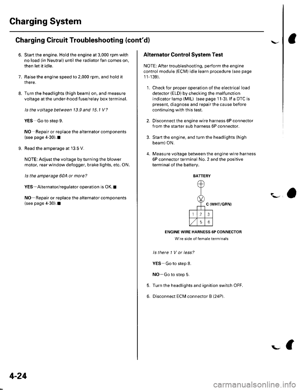
2. Disconnect the engine wire harness 6P connector
from the starter sub harness 6P connector.
3. Start the engine, and turn the headlights (high
beam) ON,
4. Measure voltage between the engine wire harness
6P connector terminal No. 2 and the positive
terminal of lhe battery.
C {WHT/GRN)
ENGINE WIRE HARNESS 6P CONNECTOR
Wire side of female terminals
ls there 1 V or less?
YES Go to step 8.
NO-Go to step 5.
Turn the headlights and ignition switch OFF.
Disconnect ECM connector B (24P).
5.
6.
BATTERY
Page 61 of 1139
Charging System
Drive Belt Inspection
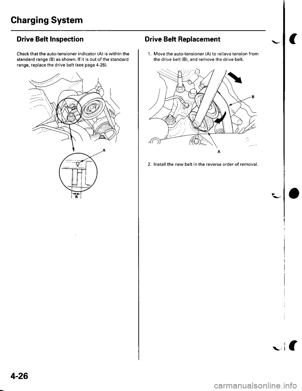
Check that the auto-tensioner indicator (A) is within the
standard range (B) as shown. lf it is out of the standard
range, replace the drive belt (see page 4-26).
4-26
Drive Belt Replacement
1, Move the auto-tensioner (A) to relieve tension from
the drive belt (B). and remove the drive belt.
2. Installthe new belt in the reverse order of removal.
Page 62 of 1139
\Drive Belt Auto-tensioner Inspection
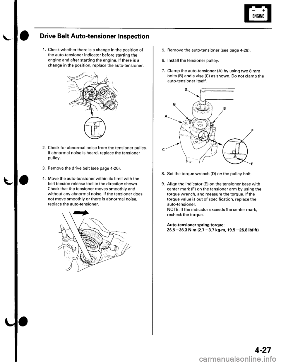
1.Check whether there is a change in the position of
the auto-tensioner indicator before starting the
engine and after starting the engine. lf there is a
change in the position, replace the auto-tensioner.
3.
Check for abnormal noise from the tensioner pulley.
lf abnormal noise is heard, replace the tensioner
pulley.
Remove the drive belt (see page 4-26).
lMove the auto-tensioner within its limit with the
belt tension release tool in the direction shown.
Check that the tensioner moves smoothly and
without any abnormal noise. lf the tensioner does
not move smoothly or there is abnormal noise,
replace the auto-tensioner.
7.
8.
Remove the auto-tensioner (see page 4-28).
Install the tensioner pulley.
Clamp the auto-tensioner (A) by using two 8 mm
bolts (B) and a vise (C) as shown. Do not clamp the
auto-tensioner itself .
Set the torque wrench (D) on the pulley bolt.
Align the indicator {E) on the tensioner base with
center mark (F) on the tensioner arm by using the
torque wrench, and measure the torque. lf the
torque value is out of specification, replace the
auto-tensioner,
NOTE; lf the indicator exceeds the center mark,
recheck the torque.
Auto-tensioner spring torque:
26.5-36.3 N.m 12.7-3.7 kg.m, 19.5-26.8lbt.ft)
9.
4-27
Page 71 of 1139
Gruise Control
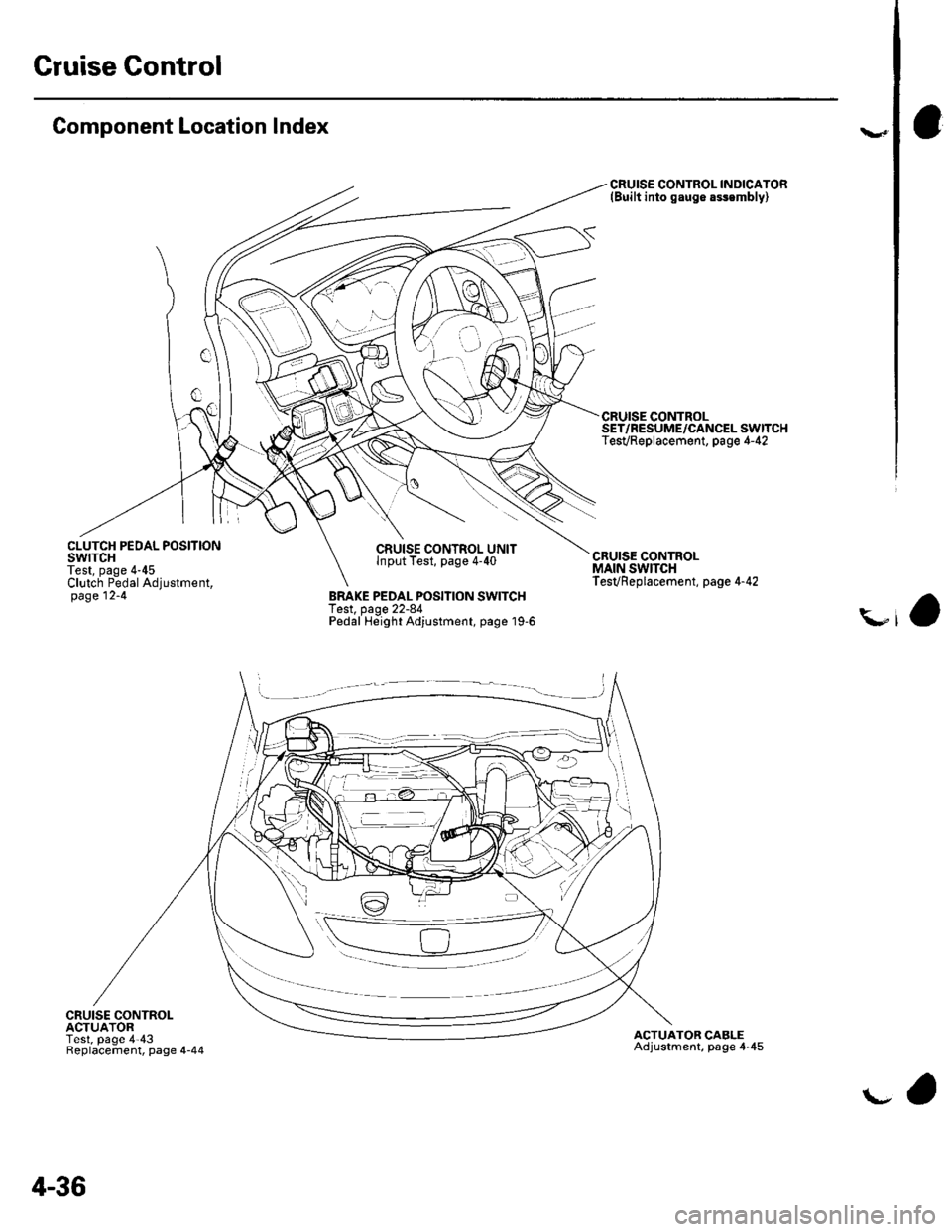
Component Location Index
CLUTCH PEDAL POSITIONswtTcHTest, page 4-45Clutch Pedal Adjustment,page 12-4
t.- _,- _
CRUISE CONTROLACTUATORTest, page 4'43Replacement, page 4-44
CRUISE CONTROL UNITlnput Test, page 4-40
BRAKE PEDAL POSITION SWITCHTest, page 22-84Pedal Height Adjustment, page '19-6
CRUISE CONTROL INDICATOR(Built into gaug6 assembly)
ACTUATOR CABLEAdjustment, page 4-45
-ll
4-36
\-a
Page 73 of 1139
Cruise Control
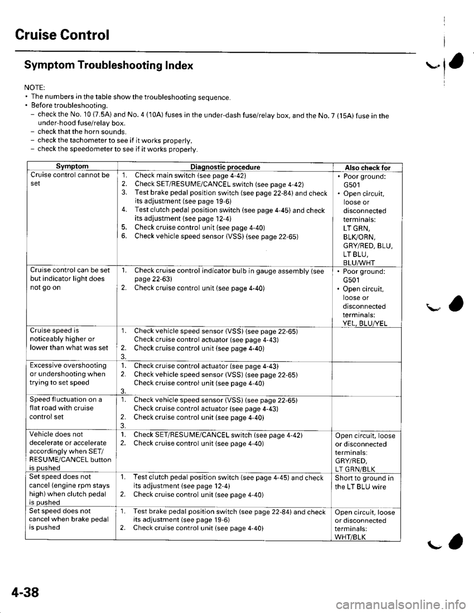
Symptom Troubleshooting Index
NOTE:' The numbers in the table showthetroubleshooting sequence.. Before troubleshooting.- check the No, 10 (7.5A) and No. 4 (10A) fuses in the under-dash fuse/relay box. and the No. 7 (15A) fuse in theunder-hood fuse/relay box,- check that the horn sounds.- check the tachometer to see if it works properly.- check the speedometer lo see if it works properly.
SymptomDiagnostic procedureAlso check forCruise control cannot be
set
1. Check main switch (see page 4-42)
2. Check SET/RESUME/CANCEL switch (see page 4-42)
3. Test brake pedal position switch (see page 22-84) and checkits adjustment {see page 19,6)
4. Test clutch pedal position switch (see page 4-45) and check
its adjustment (see page 12-41
5. Check cruise control unit {see page 4-40}
6. Check vehicle speed sensor (VSS) (see page 22-65)
. Poor ground:
G501. Open circuit,
loose or
disconnected
term inals:
LT GRN,
BLI(ORN.
GRY/RED, BLU.
LT BLU,
BLUAA/HTCruise control can be set
but indicator light does
not go on
1. Check cruise control indicator bulb in gauge assembly {seepage 22-631
2. Check cruise control unit (see page 4-40)
. Poor ground:
G501. Open circuit,
loose or
disconnected
termrnats:
YEL, BLUA/ELar, 'i.a c^aa.l ic
noticeably higher or
lower than what was set
1. Check vehicle speed sensor (VSS) {see page 22-65)
Check cruise control actuator {see page 4-43)
2. Check cruise control unit (see page 4-40)
Excessive overshooting
or undershooting when
trying to set speed
1. Check cruise control actuator (see page 4-43)
2. Check vehicle speed sensor (VSS) (see page 22-65)
Check cruise control unit (see page 4-40)
3.
Speed fluctuation on a
flat road with cruise
control set
1. Check vehicle speed sensor (VSS) (see page 22-65)
Check cruise control actuator (see page 4-43)
2. Check cruise control unit (see page 4-40)
Vehicle does not
decelerate or accelerate
accordingly when SET/
RESUME/CANCEL button
is pushed
1. Check SET/RESU ME/CANCEL switch (see page 4-42)2. Check cruise control unit {see page 4-40)
Open circuit, loose
or disconnected
terminals:
GRY/RED,
LT GRN/BLKSet speed does not
cancel (engine rpm stays
high) when clutch pedal
is pushed
1. Testclutch pedal position switch (see page 4-45) and checkits adjustment (see page 12-4)
2. Check cruise control unit (see page 4-40)
Short to ground in
the LT BLU wire
Set speed does not
cancel when brake pedal
is pushed
'1. Test brake pedal position switch (see page 22-84) and checkits adjustment (see page 19-6)
2. Check cruise control unit (see page 4-40)
Open circuit, loose
or disconnected
terminals:
WHT/BLK
4-38
g,
Page 76 of 1139
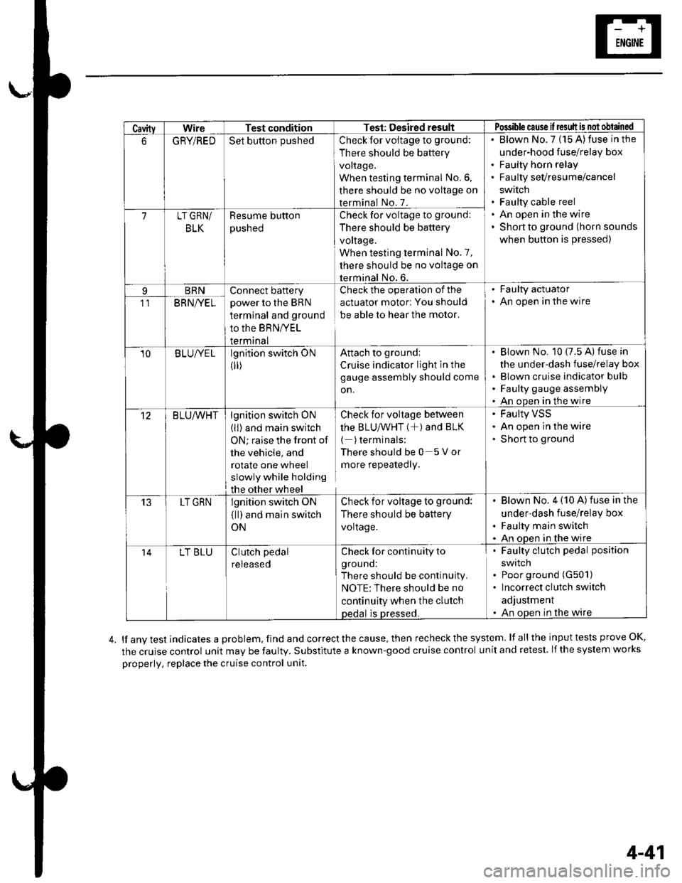
CavityWireTest conditionTest: Desired resultPossible cause il result is not obtained
6GRYiREDSet button pushedCheck for voltage to ground:
There should be battery
voltage,
When testing terminal No.6,
there should be no voltage on
terminal No. 7.
Blown No.7 (15 A)fuse in the
under-hood fuse/relay box
Faulty horn relay
Faulty sevresume/cancel
swrtch
Faulty cable reel
An open in the wire
Shon to ground (horn sounds
when button is pressed)
7LT GRN/
BLK
Resume button
pusneo
Check for voltage to ground:
There should be battery
voltage.
When testing terminal No.7,
there should be no voltage on
terminal No. 6.
BRNConnect battery
power to the BRN
terminal and ground
to the BRNIVEL
termrnal
Check the operation of the
actuator motor: You should
be able to hear the motor.
. Faulty actuator. An open in the wire11BRNI/EL
10B LUIVE Llgnition switch ON
0r)
Attach to groundi
Cruise indicator light in the
gauge assembly should come
on.
Blown No. 10 (7.5 A) fuse in
the under-dash fuse/relay box
Blown cruise indicator bulfl
Faulty gauge assembly
An open in the wire
12BLU/VVHTlgnition switch ON
(ll) and main switch
ON; raise the front of
the vehicle, and
rotate one wheel
slowly while holding
the other wheel
Check for voltage between
thE BLU/VVHT (+) ANd BLK
( )terminals:
Thereshouldbe0 5Vor
more repeatedly.
Faulty VSS
An open in the wire
Short to ground
13LT GRNlgnition switch oN
{ll) and main switch
ON
Check for voltage to ground:
There should be battery
voltage.
Blown No. 4 (10 A)fuse in the
under-dash fuse/relay box
Faulty main switch
An oDen in the wire
14LT BLUClutch pedal
reteaseo
Check for continuity to
grouno:
There should be continuity.
NOTE:There should be no
continuity when the clutch
oedal is Dressed.
Faulty clutch pedal position
swtlcn
Poor ground (G501)
Incorrect clutch switch
adjustment
An open in the wire
lf any test indicates a problem, find and correct the cause, then recheck the system. lf all the input tests prove OK,
the cruise control unit may be faulty. Substitute a known-good cruise control unit and retest. lf the system works
properly, replace the cruise control unit.
4-41
Page 124 of 1139
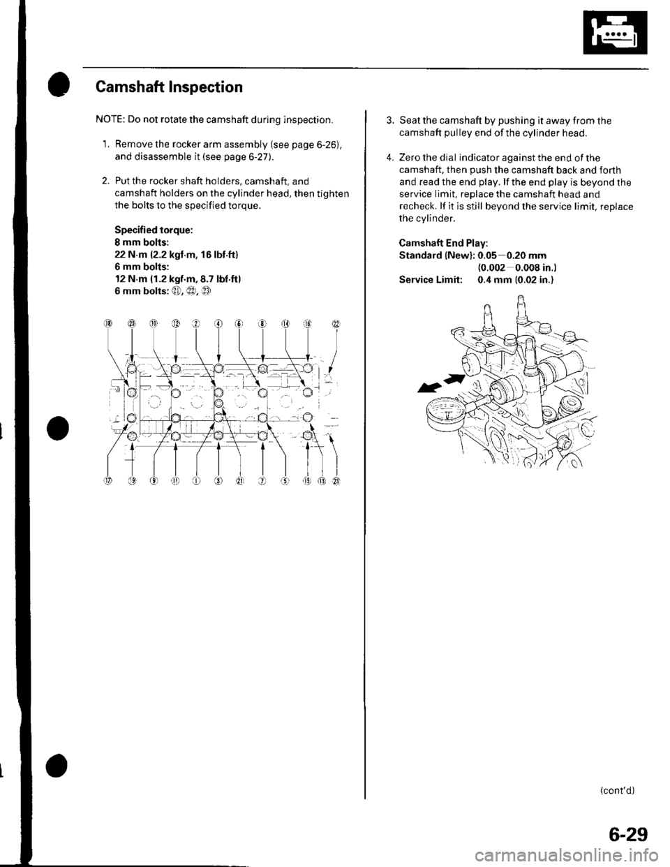
Gamshaft Inspection
NOTE: Do not rotate the camshaft during inspection.
1. Remove the rocker arm assembly (see page 6-26).
and disassemble it (see page 6-27).
2. Put the rocker shaft holders, camshaft, and
camshaft holders on the cylinder head, then tighten
the bolts to the specified torque.
Specified torque:
I mm bolis:
22 N.m {2.2 kgt m, 16lbf.ft}
6 mm bolts:
12 N.m {1.2 kgf.m,8.7 tbf.ftl
6 mm bolts: @, €0, @
I
I
3. Seat the camshaft by pushing it away from the
camshaft pulley end ofthe cylinder head.
4. Zero the dial indicator against the end of the
camshaft, then push the camshaft back and forth
and read the end play. lf the end play is beyond the
service limit, replace the camshaft head and
recheck. lf it is still beyond the service limit, replace
the cylinder.
Camshaft End Play:
Standard {New}: 0.05 0.20 mm(0.002 0.008 in.l
Service Limit: 0.4 mm (0.02 in.)
(cont'd)
6-29