Indicator HONDA CIVIC 2003 7.G Owner's Manual
[x] Cancel search | Manufacturer: HONDA, Model Year: 2003, Model line: CIVIC, Model: HONDA CIVIC 2003 7.GPages: 1139, PDF Size: 28.19 MB
Page 234 of 1139
lgnition Timing Control
The ECM contains the memory for basic ignition timing
at various engine speeds and manifold absolute
pressure. lt also adjusts the timing according to engine
coolant temperature.
Iniector Timing and Duration
The ECM contains the memory for basic discharge
duration at various engine speeds and manifold
pressures. The basic discharge duration, after being
read out from the memory, is further modified by
signals sent from various sensors to obtain the final
discharge duration.
By monitoring long term fuel trim, the ECM detects long
term malfunctions in the fuel system and sets a
Diagnostic Trouble Code {DTC).
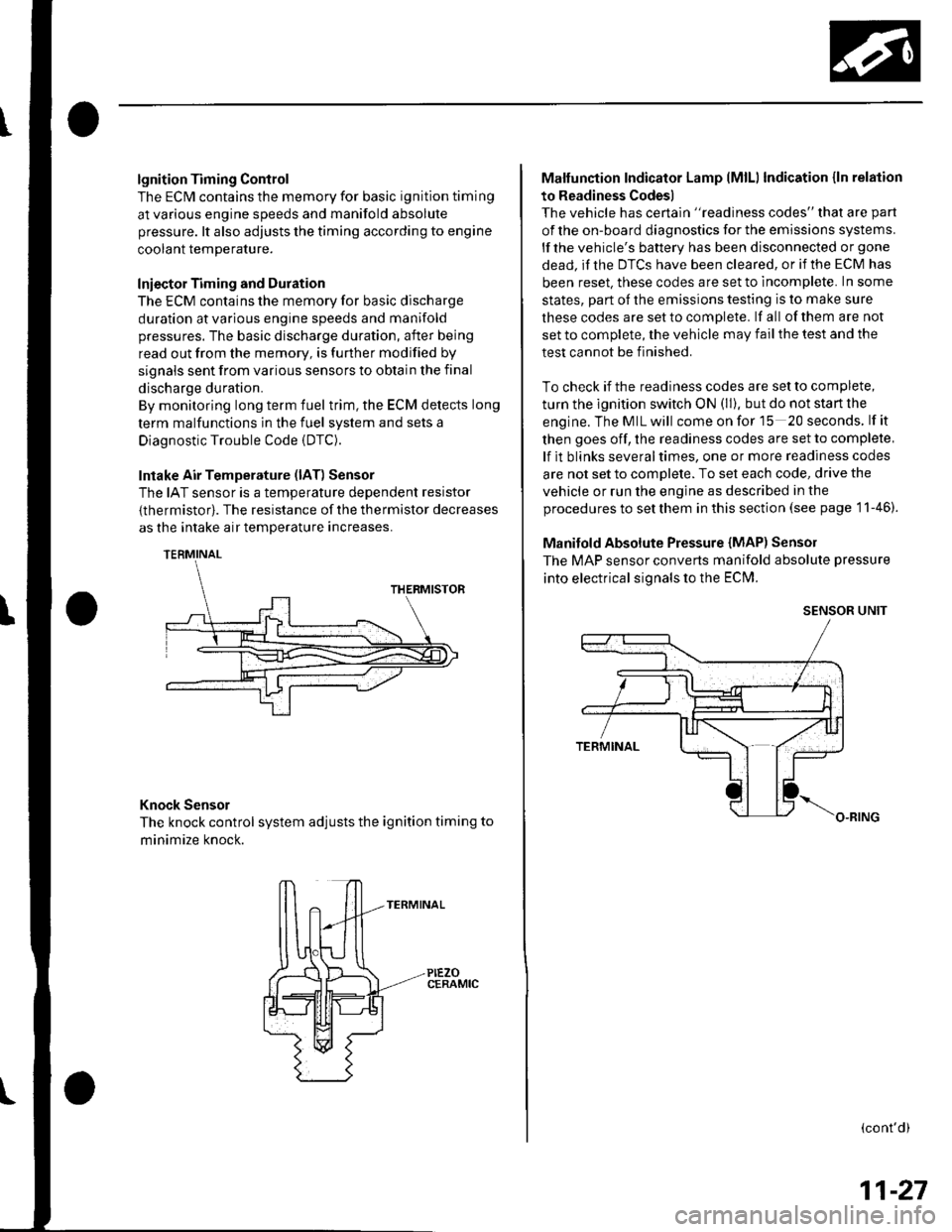
Intake Air Temperature (lAT) Sensor
The IAT sensor is a temperature dependent resistor
{thermistor). The resistance of the thermistor decreases
as the intake air temDerature increases.
Knock Sensor
The knock control system adjusts the ignition timing to
minimize knock.
PIEZOCERAMIC
Malfunction Indicator Lamp lMlLl Indication {ln relation
to Readiness Codes)
The vehicle has certain "readiness codes" that are part
of the on-board diagnostics for the emissions systems.
lf the vehicle's baftery has been disconnected or gone
dead. if the DTCS have been cleared, or if the ECM has
been reset. these codes are set to incomplete. In some
states, part of the emissions testing is to make sure
these codes are set to comDlete. lf all of them are not
set to complete, the vehicle may fail the test and the
test cannot be finished.
To check if the readiness codes are set to complete,
turn the ignition switch ON (ll). but do not start the
engine.TheMILwill comeonforlS 20seconds. lf it
then goes off, the readiness codes are set to complete,
lf it blinks severaltimes, one or more readiness codes
are not set to comolete. To set each code, drive the
vehicle or run the engine as described in the
procedures to set them in this section (see page 1 1-46).
Manifold Absolute Pressure {MAP) Senso]
The MAP sensor converts manifold absolute pressure
into electrical signals to the ECM.
SENSOR UNIT
(cont'd)
11-27
Page 304 of 1139
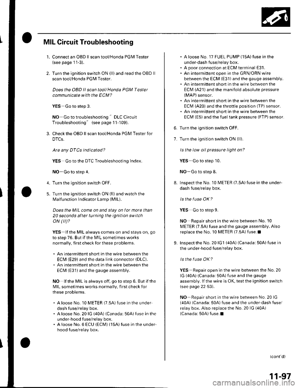
MIL Circuit Troubleshooting
1. Connect an OBD ll scan tool/Honda PGM Tester
(see page 11-3).
2. Turn the ignition switch ON (ll) and read the OBD ll
scan tool/Honda PGM Tester.
Does the OBD ll scan tool/Honda PGM Tester
communicate with the ECM?
YES Go to step 3.
NO Go to troubleshooting " DLC Circuit
Troubleshooting" (see page 11-109).
3. Check the OBD ll scan tool/Honda PGM Testerfor
DTCs.
Are any DTCs ind icated?
YES Go to the DTC Troubleshooting Index.
NO-Go to step 4.
4. Turn the ignition switch OFF.
5. Turn the ignition switch ON (ll)and watch the
lMalfunction Indicator Lamp (MlL).
Does the MIL come on and stay on for more than
20 seconds aftet turning the ignition switch
oN (tr)?
YES lf the MIL always comes on and stays on, go
to step 76. But if the lMlL sometimes works
normally, first check for these problems.
. An intermittent short in the wire between the
ECIM (E29) and the data link connector (DLC).
. An intermittent short in the wire between the
ECM (E31) and the gauge assembly.
NO lf the MIL is always off, go to step 6. But if the
lvllL sometimes works normally, first check for
these problems.
. A loose No. 10 METER (7.5A) fuse in the under
dash fuse/relay box.. A loose No. 20 lG (40A) (Canada: 50A)Iuse in the
under-hood fuse/relay box.. A ioose No. 6 ECU (ECM) (15A) fuse in the under-
hood fuse/relay box.
. A loose No. 17 FUEL PUMP (15A)fuse in the
under-dash fuse/relay box.. A poor connection at ECM terminal E31.. An intermittent open in the GRN/ORN wire
between the ECM (E31) and the gauge assembly.. An intermittent short in the wire between the
ECM (A21) and the manifold absolute pressure
(MAP) sensor.. An intermittent short in the wire between the
ECI\4 (A20) and the throttle posilion (TPi sensor.. An intermittent short in the wire between the
ECM (E5) and the fuel tank pressure (FTP) sensor.
6. Turn the ignition switch OFF.
7. Turn the ignition switch ON (ll).
ls the low oil pressure light on?
YES Go to step 10.
NO-Go to step 8.
8. Inspectthe No. 10 l\4ETER (7.5A)fuse inthe under-
dash fuse/relay box.
ls the luse OK?
YES Go to step L
NO Repair shon in the wire between No. 10
METER (7.5A)fuse and the gauge assembly. Also
replacethe No. 10 METER {7.5A) fuse.l
9. Inspect the No. 20 lG1 (40A) (Canada: 50A) fuse in
the under-hood fuse/relay box.
ls the f use OK?
YES Repair open in the wire between the No. 20
lG (40A) {Canadar 50A)fuse and the gauge
assembly. lf the wire is OK, test the ignition switch
{see page 22 53).
NO Repair short in the wire between No. 20 lG
(40A) lCanada: 50A)fuse and the under'dash fusel
relay box. Also replace the No.20 lG (40Ai
(Canada: 50A) fuse.I
(conr'd)
11-97
Page 345 of 1139
ldle Control System
ldle Speed lnspection
NOTE:' Leave the idle air control (lAC) valve connecled.. Before checking the idle speed, check these items:- The malfunction indicator lamp (MlL) has not been
reported on.- lgnition timing- Spark plugs- Air cleaner- PCV system. Pullthe parking brake lever up. Start the engine, and
make sure the headlights are off.
1. Disconnect the evaporative emission (EVAP)
canister purge valve 2P connector.
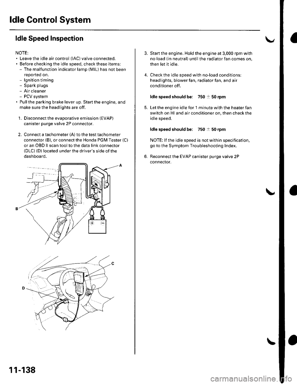
2. Connect a tachometer (A)to the test tachometer
connector (B), or connect the Honda PGM Tester (C)
or an OBD ll scan tool to the data link connector(DLC) (D) located under the driver's side of the
dashboard.
11-138
4.
3.
5.
6.
Start the engine. Hold the engine at 3,000 rpm with
no load (in neutral) until the radiator fan comes on,
then let it idle.
Check the idle speed with no-load conditions;
headlights, blower fan, radiator fan, and air
conditioner off.
ldle speed should be: 750 t 50 rpm
Let the engine idle for 1 minute with the heater fan
switch on Hl and air conditioner on, then check the
idle speed.
ldle speed should be: 750 t 50 rpm
NOTE: lf the idle speed is not wilhin specification,
go to the Symptom Troubleshooting Index,
Reconnect the EVAP canister purge valve 2P
connector.
Page 365 of 1139
Fuel Supply System
1.
4,
Low Fuel Indicator Test
Do the fuel gauge sending unit test (see page 11,
rcol.
. lf the system is OK, go to step 2.. lf the system has any malfunction, repair it.
Turn the ignition switch OFF. Remove the No. 9
BACK UP (10A) fuse from the under-hood fuse/
relay box for at least 30 seconds, then reinstall it.
Turn the ignition switch ON (ll) with the float at the
E (EMPry) position.
. lf the low fuel indicator is on, go to step 4.. lf the low fuel indicator is not on, refer to the low
fuel indicator Circuit Diagram (see page 22-58)
and check the circuit.
Turn the ignition switch OFF. Remove the No. 9
BACK UP (10A) fuse from the under-hood fuse/
relay box for at least 30 seconds, then reinstall it.
Lift the float above the LOW position.
. lf the lowfuel indicatorgoes off,the system is OK.. lf the low fuel indicator is still on, refer to the low
fuel indicator Circuit Diagram {see page 22-58),
and check the circuit.
11-158
\,
Page 367 of 1139
Intake Air System
Throttle Body Test
NOTE:. Do not adjust the throttle stop screw. lt is preset at the
factory.. lf the malfunction indicator lamp (MlL) has been
reported on, check for diagnostic trouble codes(DLCS) (see page 11 3).
1. With the engine off, check the throttle cable
movement. The cable should move without binding
or sticking.
. lf lhe cable moves OK, goto step 2.. lf the cable binds or sticks, check it and its routing.. lf the cable isfaulty, reroute itor replace itand
adjust it (see page 11-163), then go to step 2.
2. l\4ove the throttle lever by hand to see if the throftle
valve and/or shaft are too loose or too tight.
. lf there is excessive play in the throttle valve
shaft, or any binding in the throttle valve at the
fully closed position, replace the throttle body.. lf thethrottlevalve and shaft are OK, goto step3.
3. Connect the scan toolto the DLC.
Turn the ignition switch ON (ll).
Check the throttle position with the scan tool. The
reading should be about 10% when the throttle is
fully closed and about 90% when the throttle is fully
openeo.
. lf the throttle position is correct, the throttle body
is OK.. lf thethrottle position is notcorrect, replace the
throttle body.
5.
11-160
!
Page 408 of 1139
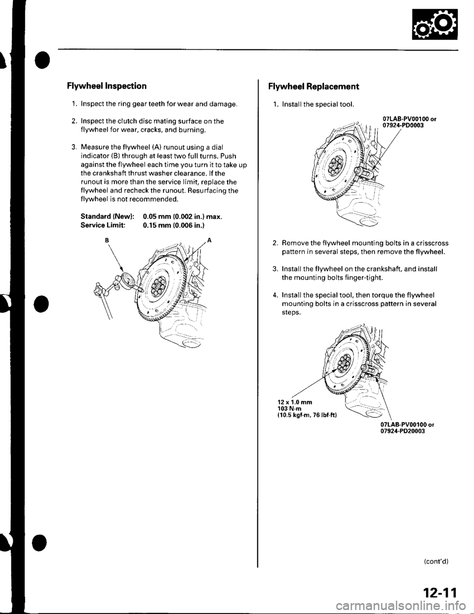
Flywheel Inspection
1. Inspect the ring gear teeth for wear and damage.
2. Inspect the clutch disc mating surface on the
flywheel for wear, cracks, and burning.
3. Measure the flywheel (A) runout using a dial
indicator (B) through at least two full turns. Push
against the flywheel each time you turn it to take up
the cra nksh aft th rust washer clea rance. lf the
runout is more than the service limit, replace the
flywheel and recheck the runout. Resurfacing the
flywheel is not recommended.
Standard (New): 0.05 mm (0.002 in.) max.
Service Limit: 0.15 mm (0.006 in.)
Flywheel Replacement
1. Installthe special tool.
2.
3.
4.
Remove the flywheel mounting bolts in a crisscross
pattern in several steps, then remove the tlywheel.
Installthe flywheel on the crankshaft, and install
the mounting bolts fingertight.
Installthe specialtool, then torque the flywheel
mounting bolts in a crisscross pattern in several
sreps.
12 x 1.0 mm103 N.m(10,s kst.m. 76 lbf ftl
(cont'd)
12-11
Page 433 of 1139
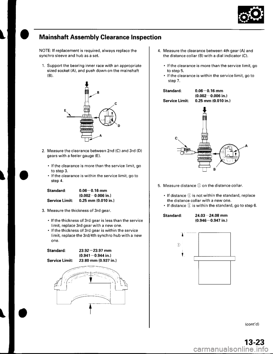
Mainshaft Assembly Clearance Inspection
NOTE: lf replacement is required, always replace the
synchro sleeve and hub as a set.
1. Support the bearing inner race with an appropriate
sized socket (A). and push down on the mainshaft(B).
Measure the clearance bet\iveen 2nd (C) and 3rd (D)
gears with a feeler gauge {E).
. lf the clearance is more than the service limit. go
to step 3.. lf the clearance is within the service limit, go to
step 4.
Standard:0.06 0.16 mm
{0.002 0.006 in.l
Service Limit: 0.25 mm (0.010 in.l
Measure the thickness of 3rd gear.
. lf thethickness of 3rd gearis lessthanthe service
limit, replace 3rd gearwith a new one.. lf thethickness of 3rd geariswithintheservice
limit, replace the 3rd/4th synchro hub with a new
one.
Standard: 23.92-23.97 mm(0.941 0.944 in.)
Service Limit: 23.80 mm (0.937 in.)
4. Measure the clearance between 4th gear (A) and
the distance collar (B) with a dial indicator (C).
. lf the clearance is more than the service limit, go
to step 5.. lf the clearance is within the service limit, go to
step 7.
Standard: 0.06 0.16 mnl(0.002 0.006 in.)
Service Limit: 0.25 mm {0.010 in.)
Measure distance O on the distance co[ar.
. lf distance't is notwithin the standard, replace
the distance collar with a new one.. lf distance e is within the standard, go to step 6.
Standard:24.03 24.08 mm
{0.946-0.9/u in.}
(cont'd)
13-23
Page 434 of 1139
Manual Transmission
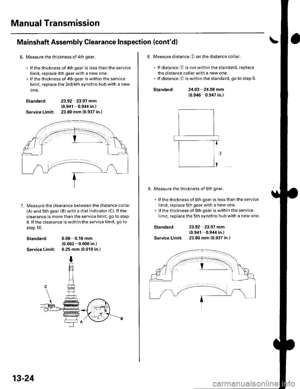
Mainshaft Assembly Clearance Inspection (cont'd)
6. Measure the thlckness of 4th gear.
. lf thethickness of 4th gear is lessthantheservice
limit, replace 4th gear with a new one.. lf thethicknessof 4th geariswithin the service
limit. replace the 3rd/4th synchro hub with a new
one.
Standard: 23.92 23.97 mm
(0.941 0.944 in.)
Service Limit: 23.80 mm (0.937 in.)
7. l\4easure the clearance between the distance collar
(A) and sth gear (B) with a dial indicator (C). lfthe
clearance is more than the service limit. go to step
8. lf the clearance is with in the service limit, go to
steD 10.
Standard: 0.06 0.16 mm(0.002-0.006 in.)
Service Limit: 0.25 mm (0.010 in.)
13-24
Standard:
Standard:
Service Limit:
8. Measure distance O on the distance collar.
. lf distance O is notwithinthestandard, replace
the distance collar with a new one.' lf distanceO iswithinthe standard, gotostep9.
24.03 24.08 mm
(0.946 0.947 in.)
9. Measure the thickness of 5th gear.
. lf thethicknessof 5th gearis lessthantheservice
limit, replace 5th gear with a new one.. lf the thickness of sth gear iswithin the service
limit. replace the 5th synchro hub with a new one.
23-92 23.97 mm
10.941 0.944 in.l
23.80 mm (0.937 in.l
Page 463 of 1139
\
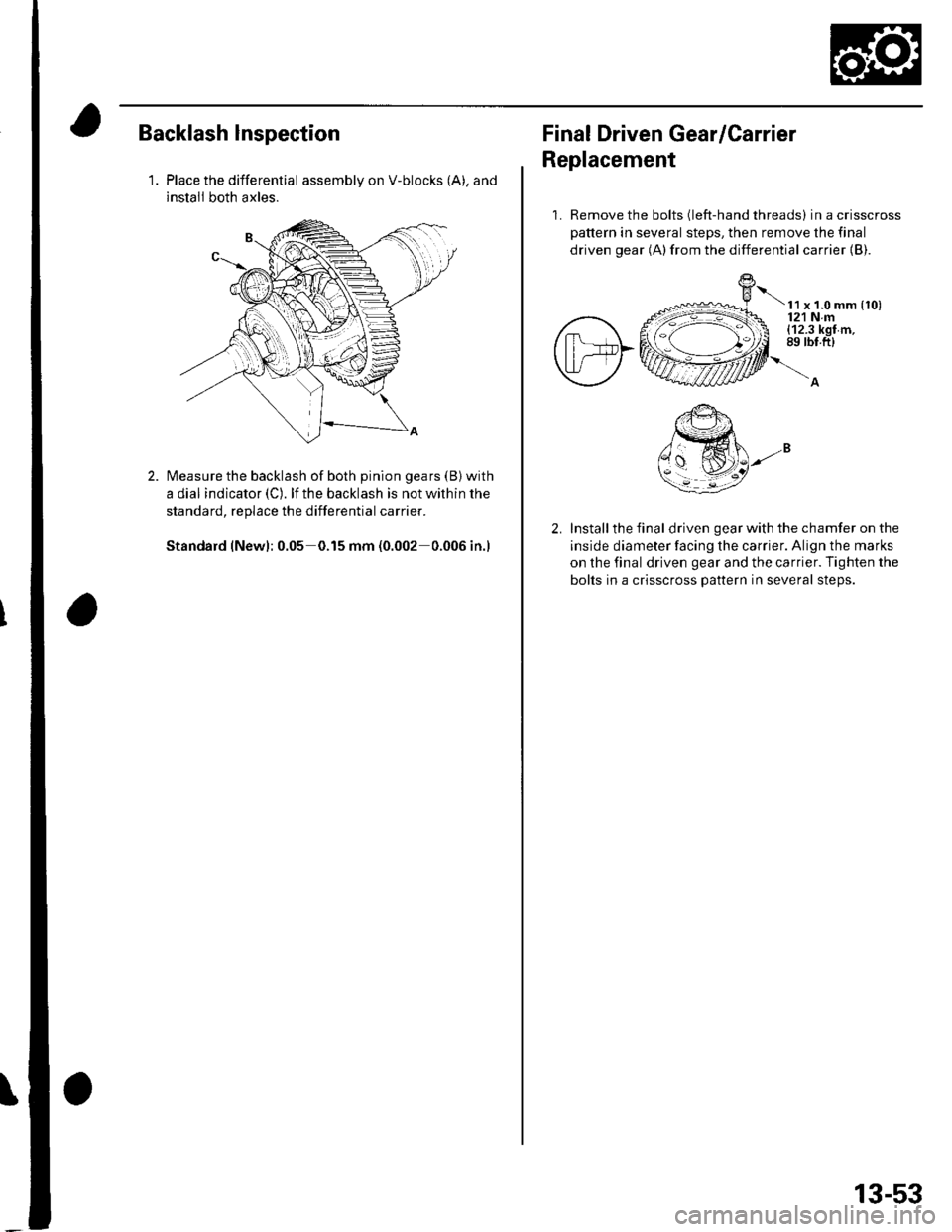
Backlash lnspection
1.Place the differential assembly on V-blocks (A), and
install both axles.
Measure the backlash of both pinion gears (B) with
a dial indicator (C). lf the backlash is not within the
standard, replace the differential carrier.
Standard (New): 0.05 0.15 mm (0.002 0.006 in.)
Final Driven Gear/Carrier
Replacement
1. Remove the bolts (left-hand threads) in a crisscross
pattern in several steps, then remove the final
driven gear (A)from the differential carrier {B).
t x t.o mm {to)121 Nm(12.3 kgf m,89 rbt.ft)
Install the final driven gear with the chamfer on the
inside diameter facing the carrier. Align the marks
on the final driven gear and the carrier. Tighten the
bolts in a crisscross pattern in several steps.
13-53
Page 509 of 1139
EPS Components
aGeneral Troubleshooting Information
EPS Indicator
Under normal conditions, the EPS indicator comes on when
the ignitlon switch is turned to the ON (ll) position, then goes
off after the engine is started. This indicates that the bulb and
its circuit are operating correctly.
lf there is any trouble in the system after the engine is started,
the EPS indicator will stay on, and the power assist is turned
off.
When EPS indicator light comes on, the control unit
memorizes the DTC. In this case, the control unit will not
activate the EPS system after the engine starts again, but it
keeps the EPS indicator on.
When DTC 12, 16, 17, 18 or 67 is stored in the control unit, the
EPS indicator will stay on until the DTC is erased. When a
problem is detected and the EPS indicator comes on, there are
cases when the indicator stays on untilthe ignition switch is
turned 0FF, and cases when the indicator goes off
automatically when the system returns to normal. Even though
the system is operating normally, the EPS indicator will come
on under the following conditions:
Condition '1:
. The vehicle was traveling at least 12.4 mph (20 km/h), then. A rapid change in vehicle speed was detected, then. The vehicle (or the vehicle speed sensor signal) stopped for
at least 5 seconds. The engine speed was still 'l,640rpmorhigherforatleastS
seconds
Condition 2:
After the vehicle (or the vehicle speed sensor signal) has
stopped for at least 10 seconds, yet the engine speed was still
1,640 rpm or higherfor at least 20 seconds.
Condition 3:
When the engine speed is 280 rpm or less, and the vehicle is traveling at
a speed of 6,2 mph (10 km/h) or more for 3 seconds.
To determine the actual cause ofthe problem, question the
customer about the conditions during which the problem
occured, taking the above conditions into consideration.
Diagnostic Trouble Code (DTCI
. lf the CPU cannot be activated, or itfails,the EPS indicator
comes on, but the DTC is not memorized.. The memory can hold any number of DTCS. However, when
the same DTC is detected more than once, the most recent
DTC is written over the prior DTC, therefore only one
occurrence is memorized.. The DTCS are indicated repeatedly untilthe ignition switch is
turned OFF.. lf the DTC is not memorized,the EPS indicator blinks.
. The DTCS are memorized in the EEPRO| (non-volatile
memory) therefore the memorized DTCS cannot be erased
by disconnecting the battery. Perform the specified
procedures to clear DTCS.
Self-diagnosis
Self-diagnosis can be classified into two categories:.Initial diagnosis: performed right after the engine
starts and until the EPS indicator goes off.. Regular diagnosis: performed right after the initial
diagnosis until the ignition switch is turned OFF.
The EPS control unit performs the following functions
when a problem is detected by self-diagnosis;
'1. Turns on the EPS indicator.
2. Memorizes the DTC.
3. Stops power assist and manual steering operation
begrns.
NOTE:. When DTC 23 (a problem with the circuit for
engine speed signal) is detected, the power
assist will return to normal when the vehicle
speed is 0.62 mph (1 km/h) or above.. Fot DfCs 22,23, 64, or 66 the EPS indicator goes
off automatically when the system relurns to
normal. For all other codes, the EPS indicator
goes off when the system is OK after the ignition
switch is turned from OFF to ON (ll).
Restriction on Power Assist Operation
Repeated extreme steering force. such as turning the
steering wheel continuously back-and-forth with the
vehicle stopped, causes an increase of power
consumption in the EPS motor. The increase of electric
current causes the motor to heat up. Because this heat
adversely affects the system, the control unit monitors
the electric current of the motor.
When the control unit detects heat build-up in the motor,
it reduces the electric current to the motor gradually to
protect the system, and it restricts the power assist
operation. The EPS indicator does not come on during
this function.
When steering torque is not applied to the steering
wheel, or when the ignition is turned off, and the motor
cools, the control unit will restore the power assist
gradually until it's fully restored (after approximately 15
minutes maximum).
17-18