Timing HONDA CIVIC 2003 7.G Workshop Manual
[x] Cancel search | Manufacturer: HONDA, Model Year: 2003, Model line: CIVIC, Model: HONDA CIVIC 2003 7.GPages: 1139, PDF Size: 28.19 MB
Page 14 of 1139
ne
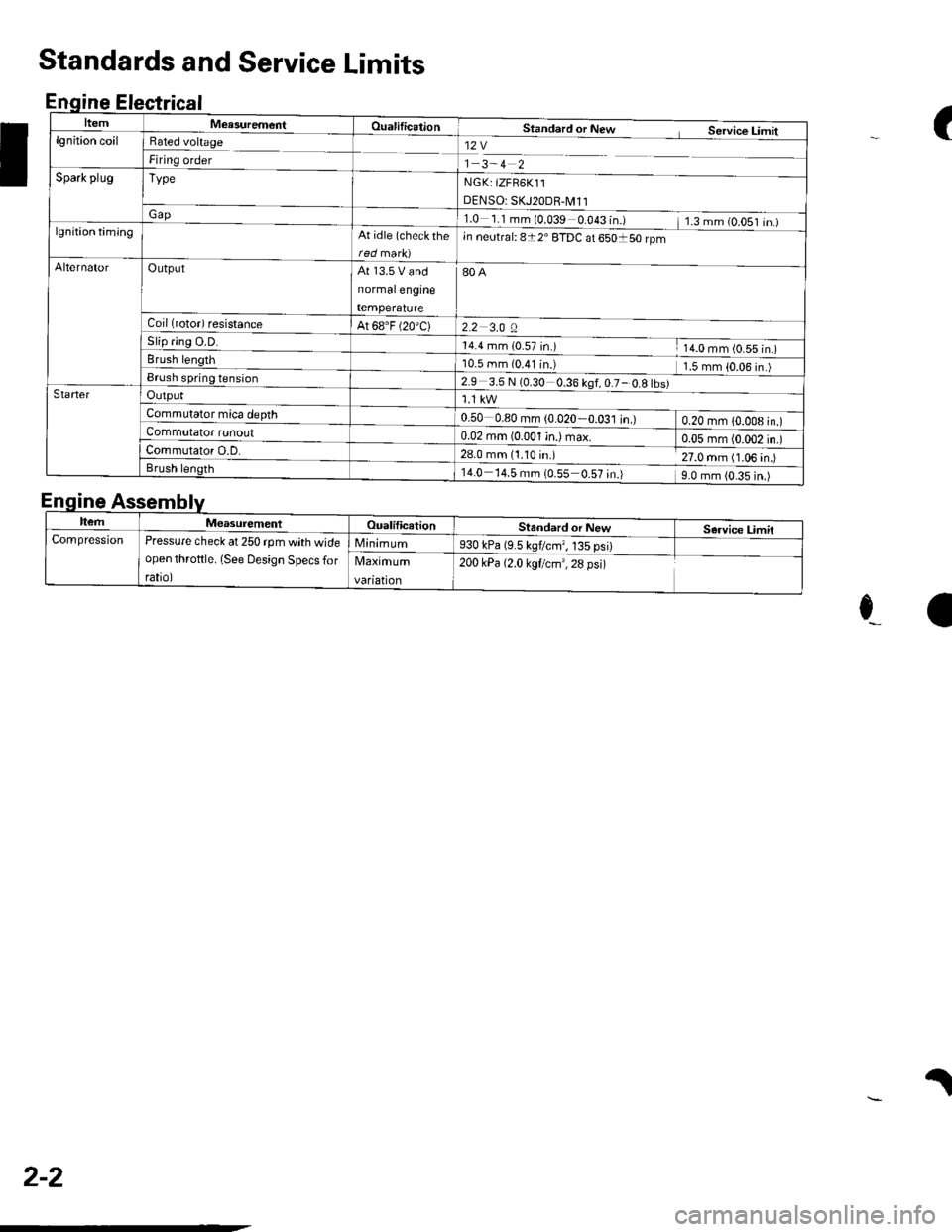
ItemMeasurementOualificationStandard or New Service Limitlgnition coilRated voltage
Firing order12V
1 3-4 2
NGK: tZFB6K11
DENSO: SKJ20DR-M11
1.0 1.1mm(0.039 0.043 in.) 1.3mm(O.OS1 in.)
Spark plugType
Gap
lgnition timingAt idle (check rhein neutral: 8t2' ETDC at 650150 rpm
AlternatorOutputAt 13.5 V and
normalengine
temperature
80A
2.2 3.0 ACoil lrotor) resistanceAt 68.F (20'C)
5|lp flng u.u.14.4 mm {0_57 in.) 14.0 mm (0.55 in.)Brush length10.5 mm (0.41 in.l 1.5 mm {0.06 in.)Brush spring tension2.9 3.5 N (0.30 0.36 kgf,0.7-0.8 tbs)StarterOutput
Commutator mica depth0.50 0.80 mm (0.020-0.031 in.) 0.20 mm 1O.OO8 in.)Commutator tunouto:BlalqryL4i) max o.o5 mm (0.002 in.)Commutator O.D.28.0 mm (1.10 in.) 27.0 mm (1.06 in.)Brush length14.0 14.5 mm {0.55 0.57 in.) 9.0 mm {0.35 in.)
(
I
Standards and Service Limits
Enqine Electrical
E
e_a
.l
nqtne
ItemMeasurementOualificationStandard or NewService LimitCompressionPressure check at 250 rpm with wide
open throftle. (See Design Specs for
rato,
Minimum930 kPa (9.5 kgflcmr, 135 psi)
Maximum
vanatton
200 kPa {2.0 kgf/cm',28 psi)
2-2
Page 36 of 1139
\.
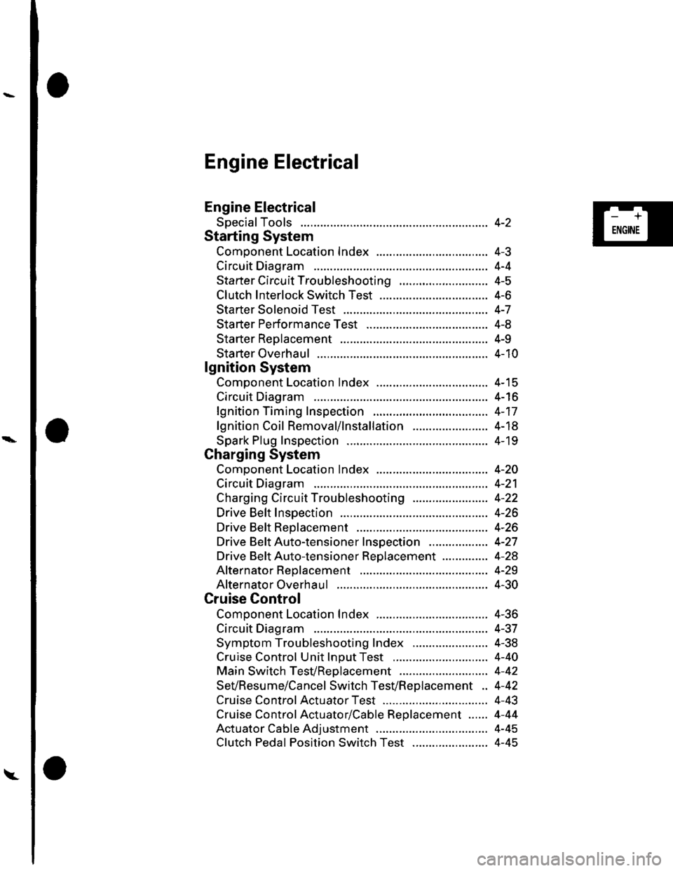
Engine Electrical
Engine Electrical
SpecialTools
Starting System
Comoonent Location Index ...............
Circuit Diagram
Starter Circu it Troubleshooting
Clutch Interlock Switch Test
Starter Solenoid Test ..............
Sta rter Performance Test
Starter Reolacement ...............
Starter Overhaul .......................
lgnition System
Component Location Index ...............
Circuit Diagram
lgnition Timing Inspection
lgnition Coil Removal/1nsta11ation .......................
Spark Plug Inspection
Charging System
Component Location Index .................................. 4-2O
Circuit Diagram ........................... 4-21
Charging Circuit Troubleshooting ....................... 4-22
Drive Belt Inspection ................... 4-26
Drive Beft Replacement .............. 4-26
Drive BeftAuto-tensioner Inspection .................. 4-27
Drive Beft Auto-tensioner Replacement .............. 4-28
Alternator Reolacement ............. 4-29
Alternator Overhaul ................ .... 4-30
Cruise Control
Component Location Index .................................. 4-36
Circuit Diagram ........................... 4-37
Symptom Troubleshooting Index ....................... 4-38
Cruise Control Unit lnDut Test ............................. 4-40
Main Switch TesVReolacement ........................... 4-42
SeVResume/Cancel Switch TesVReplacement .. 4-42
Cruise Control Actuator Test ...... 4-43
Cruise Control Actuator/Cable Replacement ...... 4-44
Actuator Cable Adjustment .................................. 4-45
Clutch Pedal Position Switch Test ....................... 4-45
4-2
4-J
4-4
4-5
4-6
4-7
4-8
4-9
4-10
4-15
4-16
4-17
4-18
4- 19
-+
ENGINE
Page 50 of 1139
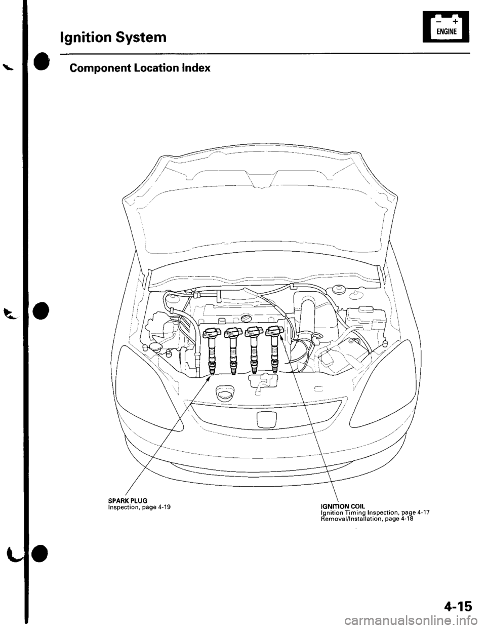
lgnition System
Component Location Index
SPARK PLUGInspection, page 4-'19IGNITION COILlgnition Timing Inspection, page 4-17Removal/lnstallation, page 4-18
4-15
Page 52 of 1139
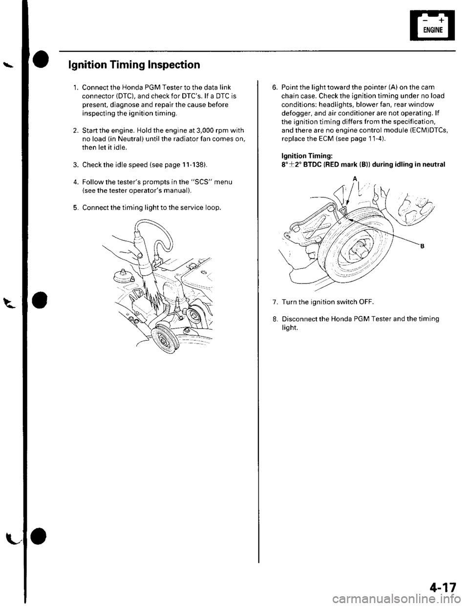
lgnition Timing Inspection
1.
4.
5.
Connect the Honda PGM Tester to the data link
connector (DTC), and check for DTC'S. lf a DTC is
present, diagnose and repair the cause before
inspecting the ignition timing.
Startthe engine. Hold the engine at 3,000 rpm with
no load (in Neutral) until the radiator fan comes on,
then let it idle.
Check the idle speed (see page 11-138).
Follow the tester's prompts in the "SCS" menu
{see the tester operator's manual),
Connect the timing light to the service loop.
o
6. Point the light toward the pointer (A) on the cam
chain case. Check the ignition timing under no load
conditions: headlights, blower fan. rear window
defogger, and air conditioner are not operaling. lf
the ignition timing differs from the specification,
and there are no engine control module {ECM)DTcs,
replace the ECM (see page 11-4)
lgnition Timing:
8"+2" BTDC {RED mark {B)) during idling in neutral
A
7. Turn the ignition switch OFF.
Disconnectthe Honda PGM Tester and thetiming
light.
4-17
Page 54 of 1139
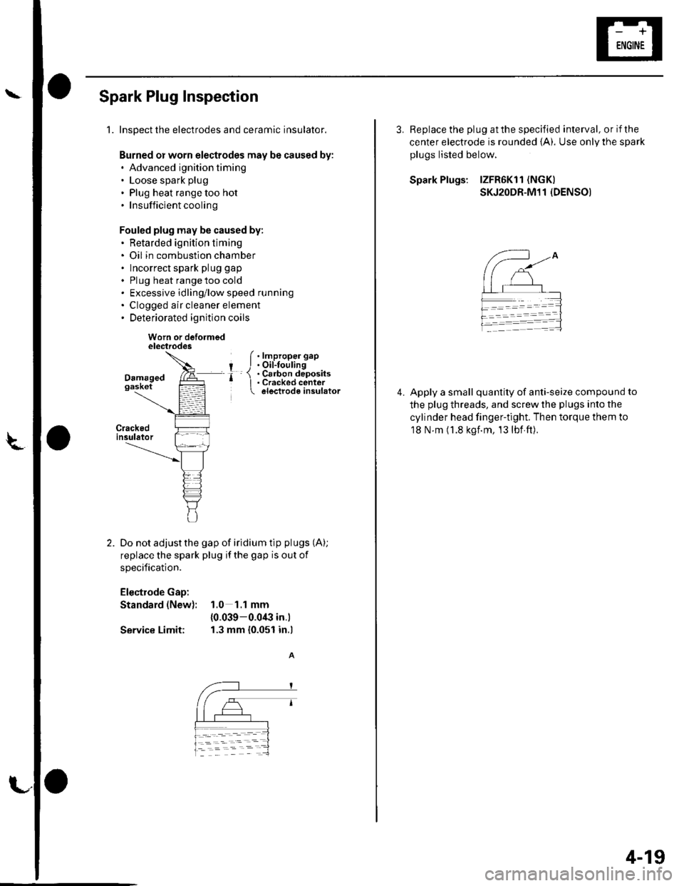
Spark Plug Inspection
1.Inspect the electrodes and ceramic insulator.
Burned or worn electrodes may be caused by:. Advanced ignition timing. Loose spark plug
. Plug heat range too hot.Insufficientcooling
Fouled plug may be caused by:. Retarded ignition timing. Oil in combustion chamber. Incorrect spark plug gap
. Plug heat range too cold. Excessive idling/low speed running. Clogged air cleaner element. Deteriorated ignition coils
Worn or deformedelectrodes
Do not adjust the gap of iridium tip plugs (A);
replace the spark plug if the gap is out of
specification.
Electrode Gap:
Standard (New): 1.0 1.1 mm
{0.039-0.0€ in.)
Service Limit: 1.3 mm {0.051 in.l
f .lmproper gap
I J.Oil-toulingr- 1 . Cs6on deposits' I . Cracked center electrode insulator
L
3. Replace the plug at the specified interval, or if the
center electrode is rounded {A). Use onlV the spark
plugs listed below.
Spark Plugs: lZFR6Kl1 (NGK)
SKJ2ODR-M11 (DENSO)
Apply a small quantity of anti-seize compound to
the plug threads, and screw the plugs into the
cylinder head finger-tight. Then torque them to
18 N m (1.8 kgf.m, 13lbf ft).
4.
4-19
Page 95 of 1139
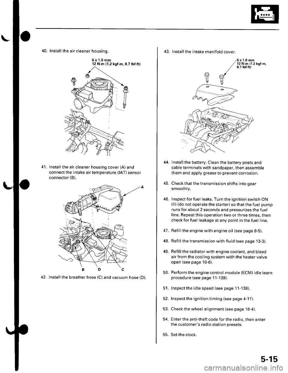
40. Install the air cleaner housinq.
6x1.0mm12 N m (1.2 kgf.m,8.7 lbt.ft)
Install the air cleaner housing cover (A) and
connect the intake air temperature (lAT) sensor
connector (B),
42. Installthe breather hose (C) and vacuum hose 1D).
41.
43. Installthe intake manifold cover.
6x1.0mm12Nm11.2kgf.m.8.7 tbf.ft)
Installthe battery. Clean the battery posts and
cable terminals with sandpaper, then assemble
them and apply grease to prevent corrosion.
Check that the transmission shifts into gear
smoothly.
Inspect for fuel leaks. Turn the ignition switch ON(ll) {do not operate the starter) so that the fuel pump
runs for about 2 seconds and pressurizes the fuel
line. Repeat this operation two or three times, then
check for fuel leakage at any point in the fuel line.
Refillthe engine with engine oil (see page 8-5).
Refill the transmission with fluid (see page 13-3).
Refill the radiator with engine coolant, and bleed
air from the cooling system with the heater valve
open (see page 10-6).
Perform the engine control module (ECM) idle learnprocedure (see page 11-139).
Inspect the idle speed (see page 1 1-138).
Inspect the ignition timing (see page 4-17).
Check the wheel alignment {see page 18-4).
Enter the anti-theft code for the radio, then enter
the customer's radio station presets.
Set the clock.
YE
44.
41.
]tE
46.
48.
49.
52.
53.
54.
50.
51.
55.
5-15
Page 98 of 1139
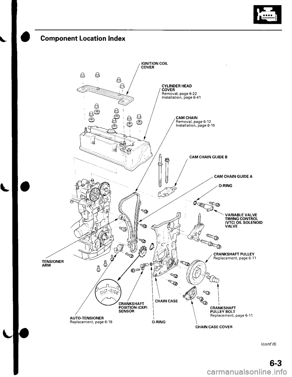
Component Location lndex
TENSIONERARM
AUTO.TENSIONERReplacement, page 6-'l I
IGNITION COILCOVER
CYLINDER HEADCOVERRemoval, page 6-22lnstallation, page 6-41
CAM CHAINBemoval, page 6-'12Installation, page 6-15
frn
|]tJ ,"p
CAM CHAIN GUIDE B
CAM CHAIN GUIDE A
VARIABLE VALVETIMING CONTROLtwc) olL soLENotDVALVE
CRANKSHAFT PULLEYReplacement, page 6 11
O-RING
(cont'd)
6-3
Page 103 of 1139
Cylinder Head
WEC Rocker Arms Test (cont'dl
'10. Loosen the valve on the regulator, and apply thespecified air pressure.
Specified air pressure:
290 kPa 13.0 kgt/cm', 42 psi)
NOTE: lf the synchronizing piston does not moveafter applying air pressure; move the primary orsecondary rocker arm up and down manually byrotating the crankshaft clockwise.
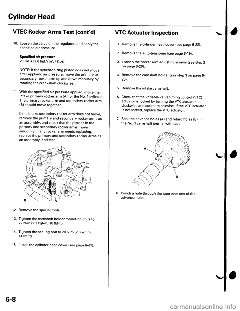
11. With the specified air pressure applied, move theintake primary rocker arm (A)forthe No, 1 cylinder.The primary rocker arm and secondary rocker arm(B) should move together.
lf the intake secondary rocker arm does not move,
remove the primary and secondary rocker arms asan assembly, and check that the pistons in theprimary and secondary rocker arms move
smoothly. lf any rocker arm needs replacing,
replace the primary and secondary rocker arms asan assembly, and test.
Remove the special tools.
Tighten the camshaft holder mounting bolts lo22N m 12.2 kgf.m, 16 lbf.ft).
Tighten the sealing boltto 20 N.m (2.0 kgf.m,
14 tbf.ft).
Installthe cylinder head cover (see page 6-41).
12.
13.
14.
t5.
6-8
VTG Actuator Inspection
'11. Remove the cylinder head cover (see page 6-22lr.
2. Remove the auto-tensioner (see page 6-19).
3. Loosen the rocker arm adjusting screws lsee step 2on page 6-26).
4. Remove the camshaft holder (see step 3 on page 6-
26t.
5. Remove the intake camshaft.
6, Check that the variable valve timing control (VTC)
actuator is locked by turning the VTC actuator
clockwise and counterclockwise. lf the VTC actuatoris not locked, replace the VTC actuator.
7. Seal the advance holes (A)and retard holes (B) in
the No. 1 camshaft journal with tape.
Punch a hole through the tape over one of theadvance holes.
Page 104 of 1139
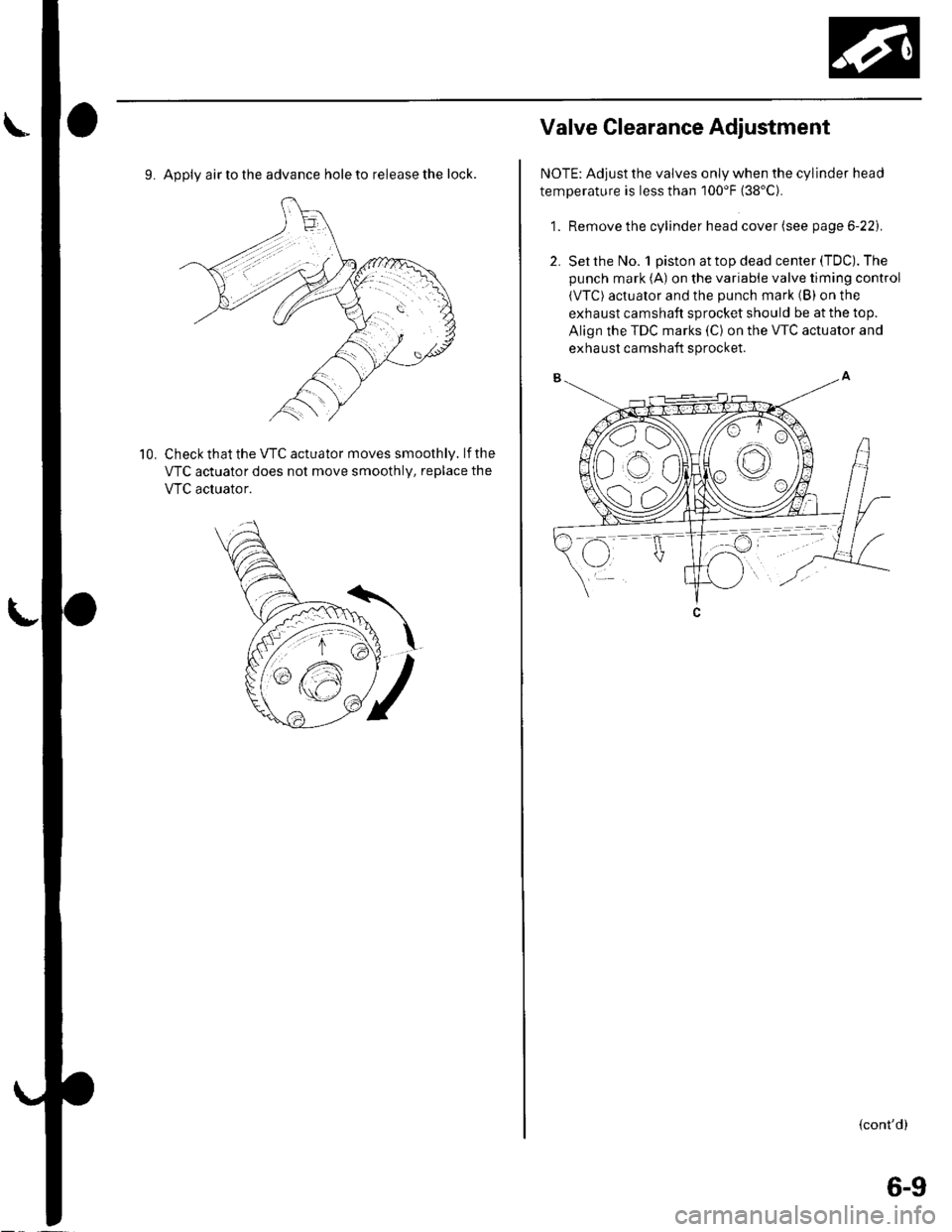
9. Apply air to the advance hole to release the lock.
Check that the VTC actuator moves smoothly. lf the
VTC actuator does not move smoothly, replace the
VTC acluator.
10.
Valve Glearance Adiustment
NOTE: Adjust the valves only when the cylinder head
temperature is less than 100'F (38'C).
1. Remove the cylinder head cover (see page 6-22).
2. Set the No. 1 piston at top dead center (TDC). The
punch mark (A) on the variable valve timing control
(VTC) actuator and the punch mark (B) on the
exhaust camshaft sprocket should be at the top.
Align the TDC marks (C) on the VTC actuator and
exhaust camshaft sprocket.
{cont'd)
6-9
Page 108 of 1139
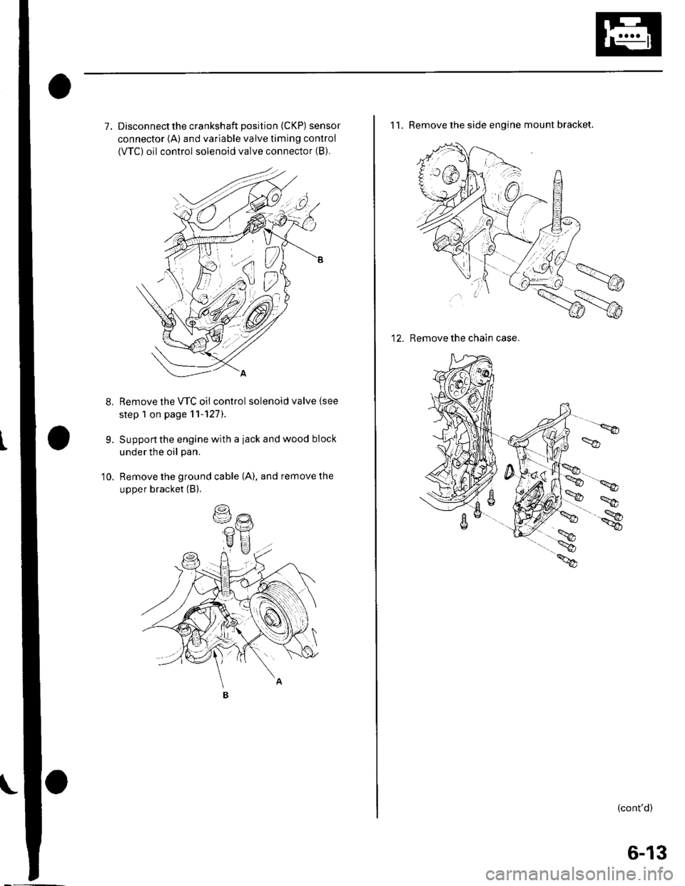
7. Disconnectthe crankshaft position (CKP) sensor
connector {A) and variable valve timing control
{VTC) oil control solenoid valve connector (B).
Remove the VTC oil control solenoid valve (see
step 1 on page 11-127).
Support the engine with a iack and wood block
under the oil pan.
Remove the ground cable (A). and remove the
upper bracket (B).
9.
10.
11. Remove the side engine mount bracket.
12. Remove the chain case.
(cont'd)
6-13