battery terminals HONDA CR-V 1997 RD1-RD3 / 1.G Owners Manual
[x] Cancel search | Manufacturer: HONDA, Model Year: 1997, Model line: CR-V, Model: HONDA CR-V 1997 RD1-RD3 / 1.GPages: 1395, PDF Size: 35.62 MB
Page 1372 of 1395

)
Ftom page 2!-7 a
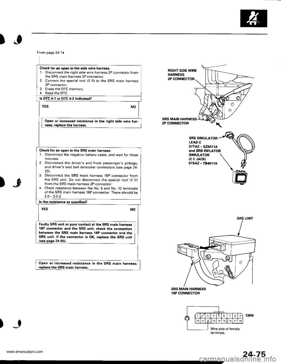
Check lor .n oo.n in the side wire hsrness:1. Disconnect the right side wire harness 2P connector fromthe SRS main harness 2P connector.2. Connect the special tool (2 Oi to the SRS main harness2P connector.3. Erase the DTC memory.4. Bead the DTC.
ls DTC 4-1 or DTC 4-2 indicated?
NOYES
Open or inc.oased resistance in th€ right side wire har-ness; replace the harness.
Check tor an open in the SRS main harness:1. Disconnect the negative battery cable, and wait for threemtnutes.2. Disconnect the driver's and front passenger's airbags,and driver's seat belt tensioner connectors (see page 24-23\.3. Disconnect the SRS main harness 18P connector fromthe SRS unit. Do not disconnect the special tool (2 0)from the SRS main harness 2P connector.4- Check resistance between the No. 5 and No. 12 terminalsof the SRS main harness 18P connector. There sho!ld be2.0 - 3.0 0.
ls the resistanca as soecified?
NOYES
Faulty SRS unit or poor contact at the SRS main harne3s18P conneclor and the SRS unit, check the connestionb€tween the SRS main harness 18P conn€ctor and th6SRS unit. lf the connector is OK, reDlace the SRS unit{see page 24-951.
Open or increesed resistanco in the SRS main h.rnes3;replace the SRS main harness.
RIGHT SIDE WIREHARNESS2P CONNECTOR
SRS MAIN HARNESS2P CONNECTOR
SRS SIMULATORLEAD C07TAZ - SZ5011A.nd SRS INFLATORSIMULATOR(2 0 JACK)07sAz - TB4011A
)"r$
SRS MAIN HABNESS18P CONNECTOR
)
le.minals.
24-75
www.emanualpro.com
Page 1374 of 1395

From page 24-76
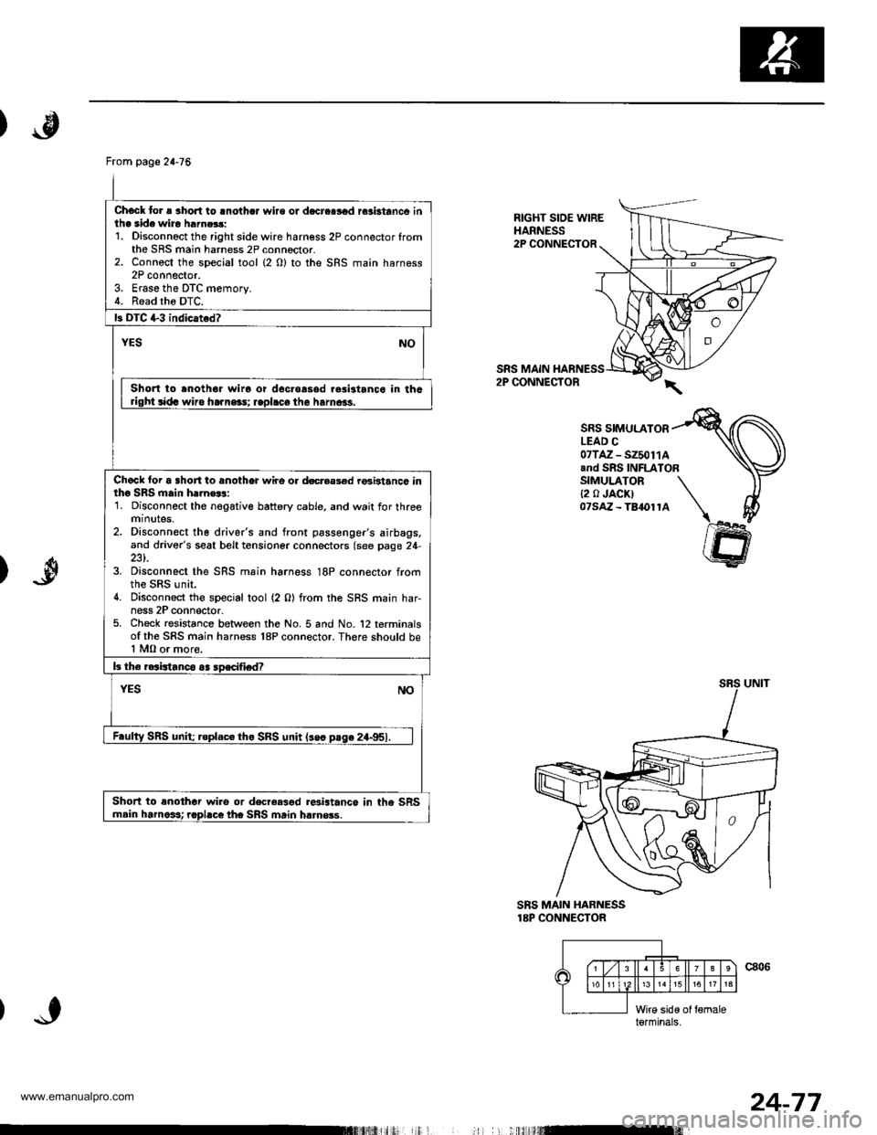
Chock to. a aho.l to lnothcr wire or d€creslod rosbtanco inth. side wiro harn.$:1. Disconnoct the right side wire harness 2P connector lromthe SRS main harness 2P connector.2. Connoct the special tool (2 O) to the SRS main harness2P connector.3. Erase the DTC memory.4. Read tho DTC.
13 DIC +3 indicated?
YESNO
Short to .noth6r wiro or doc.oasod r.sistanco in thGdght sida wiro ha]ne3s; rapl.ce the hamcas.
Chack loi a short to anothor wire o. docreas€d rGbtancc intho SRS main h.]n€$:1. Disconnect the negative battery cable, and wait for threemtnutes,2. Disconnect th6 driver's and front passenger's airbags,and driver's seat belt tensioner connectors (see page 24-
3. Disconnect the SRS main harness 18P connector fromthe SRS unit.4. Disconnect the special tool (2 0) from the SRS main har-ness 2P conn€ctor.5. Check resistance between the No. 5 and No. '12 terminalsof the SRS main harness 18P connector. There should be1 MO or more.
b the raaistanco aa soscifiedT
YESNO
F.ulty SRS unit; roplac€ tho SRS unit lseo pase 24-951.
Short to enothor wi.o or decree3od r*istance in the SRSmain harnoit rophco the SRS main ha.nsss.
RIGHT SIOE WIREHARNESS2P CONNECTOR
SRS MAIN2P CONNECTOR
SRS SIMULATORLEAD C07TAZ - SZ50114and SRS INFLATORSIMULATOR{2 0 JACK)07saz - Ta1ol1A
)
SBS MAIN HARNESS18P CONNECTOR
c806\6
15
l;iid€ of {6maleterminals,
I
24-77
www.emanualpro.com
Page 1376 of 1395

)
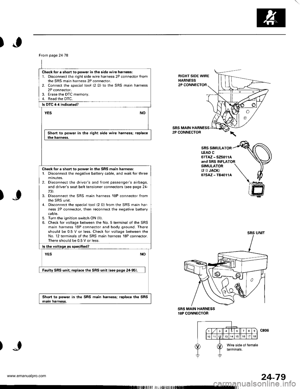
RIGHT SIDE WIREHARNESS2P CONNECTOR
SRS MAIN2P CONNECTOR
SBS SIMULATORLEAD C07TAZ - SZ5011Aand SRS INFLATORSIMULATOR \(2 0 JACK) \07sAz-T84011A \\
)J
)
@
SRS MAIN HARNESS18P CONNECTOR
Ftom page 24 78
Check for a short to power in the side wire harn6s:1. Disconnect the right side wire harness 2P connector fromthe SRS main harness 2P connector,2- Connect the special tool (2 0) to the SRS main harness2P connector.3. Erase the DTC memory.4. Read the DTC.
ls DTC 4-{ indicated?
YESNO
Short to power in the right side wire harness; replacethe harness.
Check tor a short to oow6r in the SRS main harness:1. Disconnect the negative battery cable, and wait for threemtnutes,2. Disconnect the driver's and front passenger's airbags,and driver's seat belt tensioner connectors (see page 24-23).3. Disconnect the SRS main harness 18P connector fromthe sRS unit.4. Disconnect the special tool i2 0) from the SRS main harness 2P connector, then reconnect the negative batterycaore.5. Turn the ignition switch ON (ll).
6. Check for voltage between the No. 5 terminal of the SRSmain harness 18P connector and body ground. Thereshould be 0.5 V or less. Check for voltage between theNo. 12 terminals of the SRS main harness 18P connector.There should be 0.5 V or less.
ls the voltage as specified?
NOYES
Faulty SRS unit; replace the SRS unit (see pase 24-95).
Short to power in the SRS main harness; replace the SRSmain harness.
24-79
www.emanualpro.com