reset HONDA CR-V 1997 RD1-RD3 / 1.G Workshop Manual
[x] Cancel search | Manufacturer: HONDA, Model Year: 1997, Model line: CR-V, Model: HONDA CR-V 1997 RD1-RD3 / 1.GPages: 1395, PDF Size: 35.62 MB
Page 55 of 1395

Starting System
Starter Test
NOTE: The air temperature must be between 59 and'100'F (15 and 38"C) before testing.
Recommended Procedure:
. Use a staner system tester.
. Connect and operate the equipment in accordance
with the manufacturer's instructions.
. Test and troubleshoot as described.
Alte.nate Procedure:
. Use the following equipment:- Ammeter, 0 - 400 A- Voltmeter, 0 - 20 V (accurate within 0.1 volt)
Tachometer,0 - 1,200 rpm
. Hook up a voltmeter and ammeter as shown.
NOTE: After this test, or any subsequent repair. reset
the ECM/PCM to clear any codes (see section 1 1).
Check the Starter Engagement:
'1. Remove the No. 44 (15 A) fuse from the under-hood
fuse/relay box.
2. Turn the ignition switch to START (lll) with the shift
lever in E or E position (A/T) or with the clutch
pedal depressed {M/T). The starter should crank the
eng ine.
. lf the starter does not crank the engine, go to
step 3.
. lf it cranks the engine erratically or too slowly, go
to "Check for Wear and Damage" on the next
page.
NEGATIVE TERMINAL
4.
5.
6.
7.
8.
Check the battery, battery positive cable, ground.
staner cut relay, and the wire connections for loose-
ness and corrosion. Test again.
lf the staner still does not crank the engine, go to
step 4.
Unplug the connector (BLK /VHT wire and solenoid
terminal) from the starter.
Connect a jumper wire from the baftery positive (+)
terminal to the solenoid terminal.
The starter should crank the engine.
. lf the starter still does not crank the engine,
remove it, and diagnose its internal problem.
. lf the starter cranks the engine, go to step 6.
Check the ignition switch (see section 23).
Check the starter cut relay {see section 23}.
Check the IVT gear position switch (A/T) or the clutch
interlock switch (M[).
Check for an open in the wire between the ignition
switch and starter.
(cont'd)
4-5
www.emanualpro.com
Page 263 of 1395
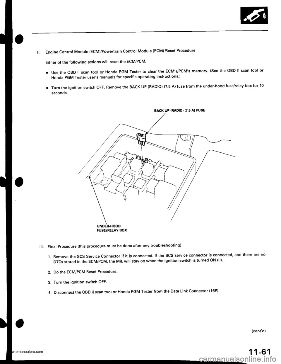
ll. Engine Controt Module (EcM)/Powertrain Control Module {PCM) Reset Procedure
Either of the following actions will reset the ECM/PCM.
. use the oBD ll scan tool or Honda PGM Tester to clear the ECM'�s/PCM'�s memory. (see the oBD ll scan tool or
Honda PGM Tester user's manuals for specific operating instructions )
. Turn the ignition switch oFF. Remove the BACK UP (RADIO) (7.5 A) fuse from the under-hood fuse/relay box for 10
seconos.
lll. Final Procedure {this procedure must be done after any troubleshooting)
1. Remove the SCS Service Connector if it is connected. lf the SCS service connector is connected. and there are no
DTCS stored in the ECM/PCM, the MIL will stay on when the ignition switch is turnsd oN (ll).
2. Do the ECM/PCM Reset Procedure.
3. Turn the ignition switch OFF
4. Disconnect the OBD ll scan tool orHonda PGM Tester from the Data Link Connector ( 16P)'
(cont'd)
1 1-61
BACK UP {RADIOI I7,5 AI FUSE
FUSE/RELAY BOX
www.emanualpro.com
Page 281 of 1395
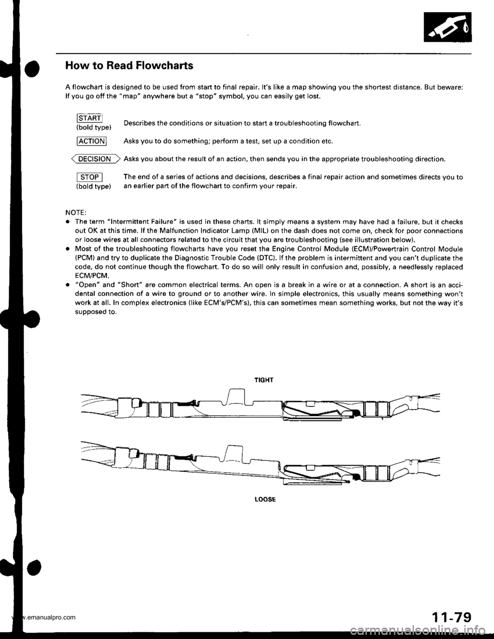
How to Read Flowcharts
A flowchart is designed to be used from start to final repair. lt's like a map showing you the shortest distance. But beware:
lf you go off the "map" anywhere but a "stop" symbol, you can easily get lost.
brARn
t.-OotO tw"t Describes the conditions or situation to start a troubleshooting flowchart.
FcTloNl Asks you to do something; perform a test, set up a condition etc.
@ Asks you about the result of an action, then sends you in the appropriate troubleshooting direction.
fS-OPl The end of a series of actions and decisions, describes a final repair action and sometimes directs you to
(bold type) an earlier part of the flowchart to confirm your repair.
NOTE:
. The term "lntermittent Failure" is used in these charts. lt simply means a system may have had a failure, but it checks
out OK at this time. lf the Malfunction Indicator Lamp (MlL) on the dash does not come on, check for poor connections
or loose wires at all connectors related to the circuit that you are troubleshooting (see illustration below).
. Most of the troubleshooting flowcharts have you reset the Engine Control Module (EcM)/Powertrain Control Module(PCM) and try to duplicate the Diagnostic Trouble Code (DTC). lf the problem is intermittent and you can't duplicate the
code, do not continue though the flowchart. To do so will only result in confusion and, possibly, a needlessly replaced
ECM/PCM,
o "Open" and "Short" are common electrical terms. An open is a break in a wire or at a connection. A short is an acci-
dental connection of a wire to ground or to another wire. ln simple electronics, this usually means something won't
work at all. In complex electronics (like ECM'S/PCM'S), this can sometimes mean something works, but not the way it's
suooosed to.
LOOSE
11-79
www.emanualpro.com
Page 312 of 1395
PGM-FI System
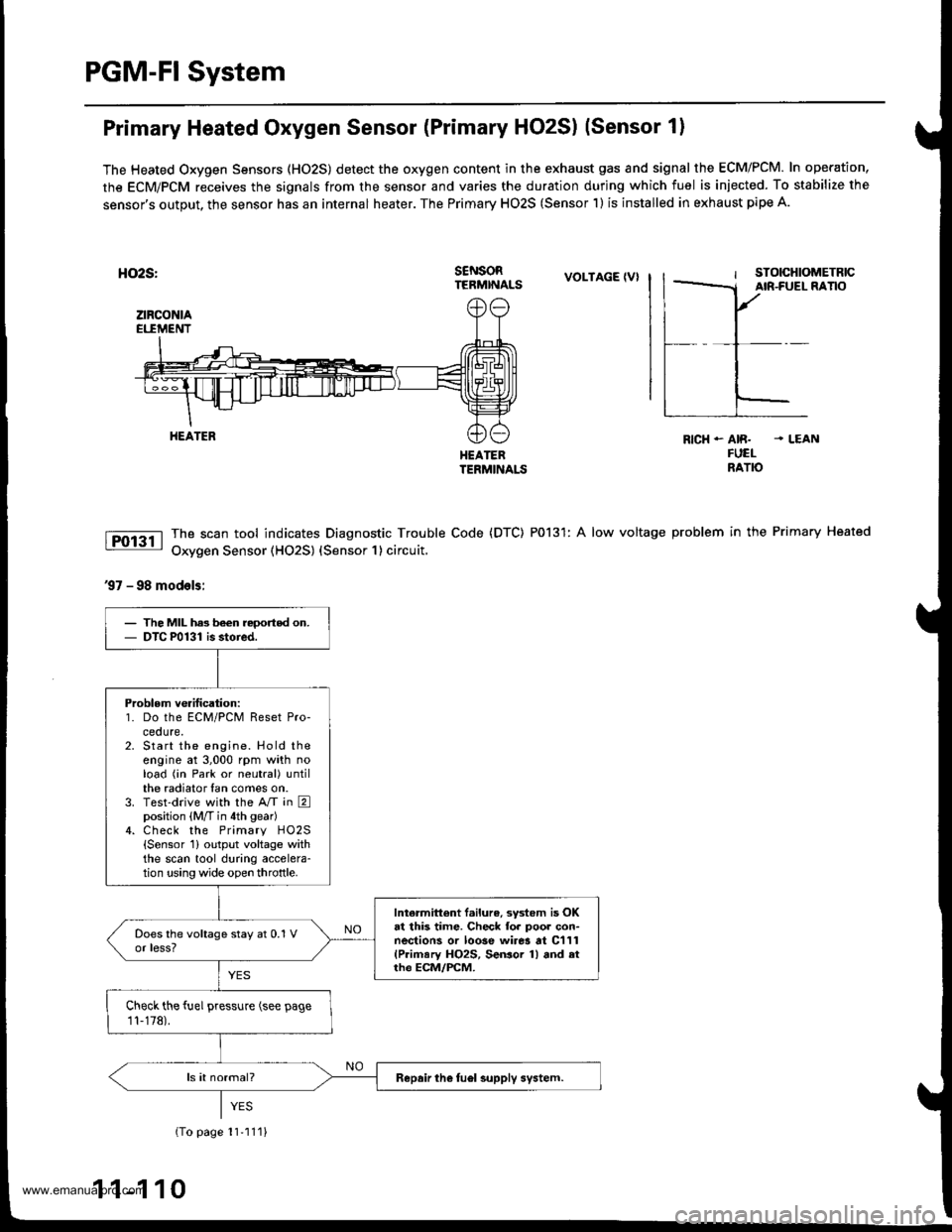
Primary Heated Oxygen Sensor (Primary HO2S) (Sensor 1)
The Heated Oxygen Sensors (HO2S) detect the oxygen content in the exhaust gas and signal the ECM/PCM. In operation,
the ECM/PCM receives the signals from the sensor and varies the duration during which fuel is iniected. To stabilize the
sensor's output, the sensor has an internal heater. The Primary HO2S (Sensor 1) is installed in exhaust pipe A.
HO2S:
ztRcoNtAEI.IMENT
s€NsoRTERMINALSVOLTAGE IVI
HEATEBTERMINALS
The scan tool indicates Diagnostic Trouble Code (DTC) P0131: A low voltage
Oxygen Sensor (HO2S) {Sensor 1} circuit,
RICH - AIR. . LEANFUELNATO
problem in the Primary Heated
37 - 98 models:
HEATER
The MIL has been reoorted on.DTC P0131 is stoied.
Problem verification:1. Do the ECM/PCM Reset Pro-ceoure.Start the engine. Hold theengine at 3,000 rpm with noload (in Park or neutral) untilthe radiator fan comes on.Test-drive with the A/T in Eposition (M/T in 4th gear)Check the Primary HO2S{Sensor 1} output voltage withthe scan tool during accelera-tion using wide open throttle.
Intermittent f.ilure, system is OKat this time. Check fo. poor con-nections or loose wirer at C111(Primary HO2S, SeGor 1) and atrh€ ECM/FCM.
Check the fuel pressure (see page
11-178).
Repair the fuel supply system.
{To page 11'111}
1 1-1 10
www.emanualpro.com
Page 314 of 1395
PGM-FI System
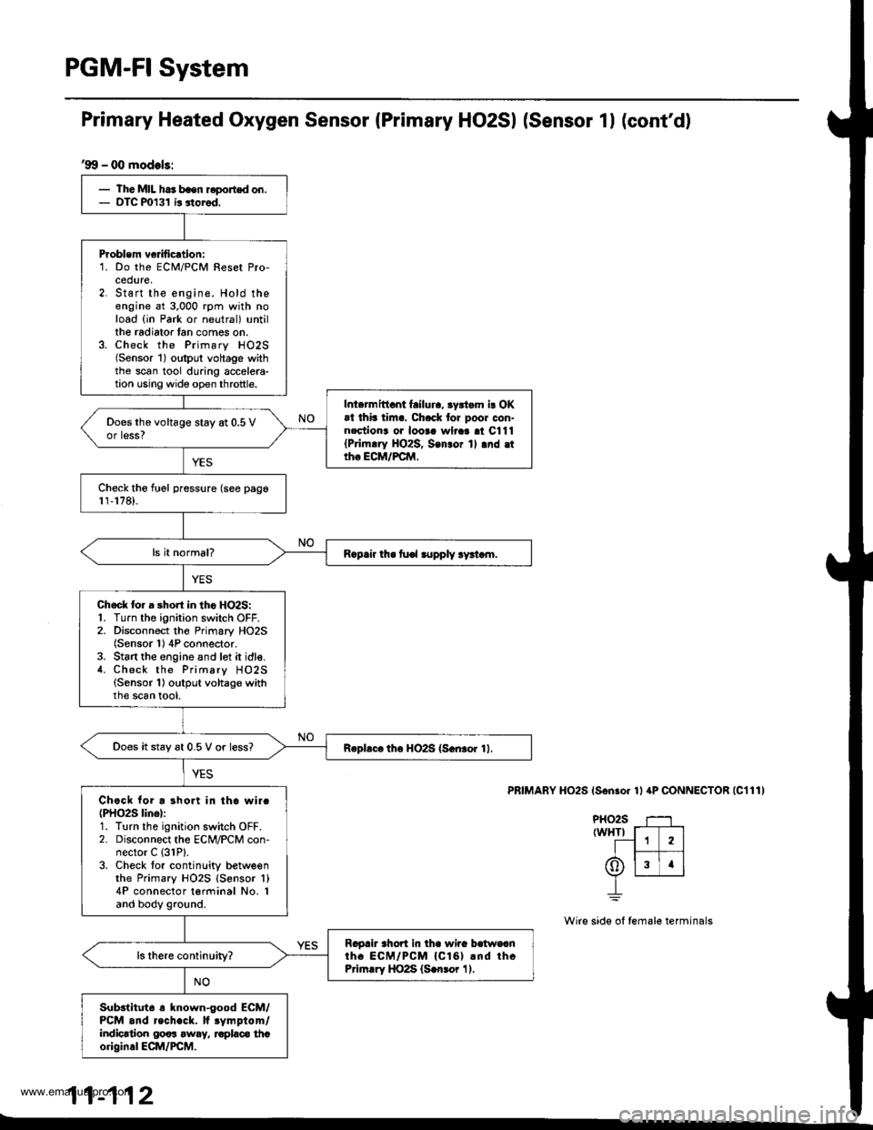
'99 - 00 models:
- The MIL has bsen reported on.- DTC P0131 ir storod.
Problem ve fication:1. Do the ECM/PCM Reset Pro-cedure,2. Start the engine. Hold theengine at 3,000 rpm with noload {in Park or neutral) untillhe radiator tan comes on.3. Check the Primary HO2S(Sensor 1) oltput voltage withthe scan tool during accelera-tion using wide op€n throttle.
Inl.rmittant failura, 3yrtam i! OKat thb tim.. Ch.ck tor poor con-nectiona oa looaa wlraa al C111{Pri|n.ry HO2S, Son3or 1l .nd .ttho ECM/FCM,
Does the voltage stay at 0.5 Vor less?
Check tho fuel pressure (see pago1r,178).
R.p.ir th. fu€l lupply ry!t.m.
Chock lor a short in tho HO2S:1. Turn the ignition switch OFF.2. Disconnect the Primary HO2S(Sensor 1) 4P connector.3. St6rt the engine and lot it idle.4. Check the Primary HO2S(Sensor 1) output voltage withthe scan tool,
Does it stay 6t 0.5 V or less?Rephc. th6 HO2S (S.n3or 11.
Chock for a short in tho wirc(PHO2S lino):1. Turn the ignition switch OFF.2. Disconnect the ECM/PCM con-nector C (31P).
3. Check tor continlity betweenthe Primary HO2S {Sensor 'l}
4P connector terminal No. Iand body ground.
Ragah rhort in tha wira balwoanth. ECM/PCM {Cl61 rnd thcPrirn.ry HO2S (S.n3or 11.
Substltut6 a known-good ECM/PCM and recheck. lf rymptom/indicrtion 00os away, raplaco thcoriginal ECM/PCM.
Primary Heated Oxygen Sensor (Primary HO2SI (Sensor 1l (cont'd)
PRIMARY HO2S (Son.or 1l aP CONNECTOR |C111)
PHO2S T--1rwHTr f-T---]
--1 1 2lI t--- 1t6)lslrlv L__r__J
_L
Wire side ol female terminals
11-112
www.emanualpro.com
Page 317 of 1395
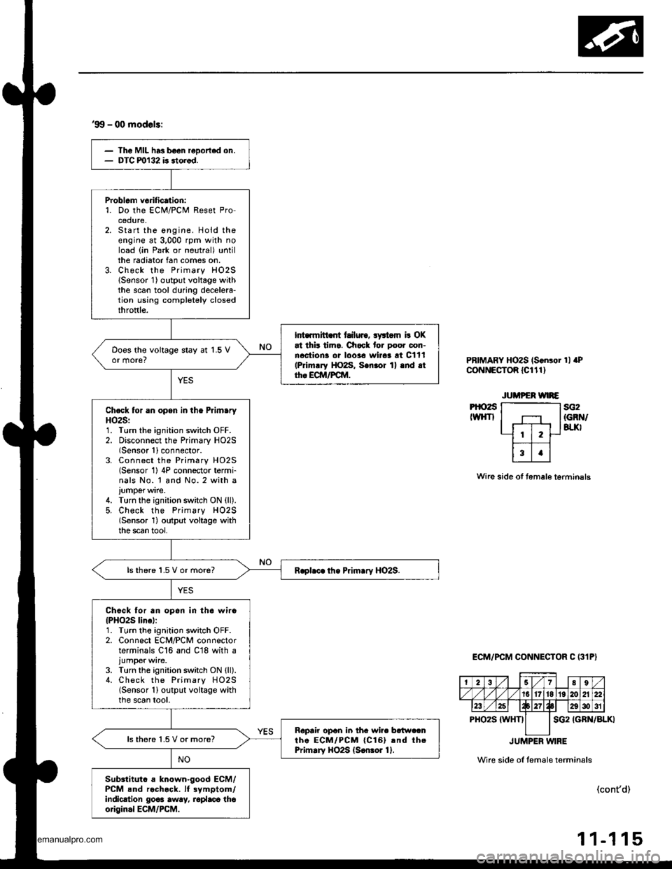
'99 - 00 modols:
Th6 Mll has b€on reDortod on.DTC ml32 is itorod.
Problem vorification:'1. Do the ECi!4/PCM Reset Procedure,Start the ongine. Hold theengine at 3,000 rpm with noload (in Park or neutral) untilthe radiator fan comes on.Check the Primary HO2SlSensor 1) output voltage withthe scan tool during decelela-tion using completely closedthroftle.
Int.rmitt .fi tailuro, syltom b OKat thit tima. Check for poor con-nactiona oi loo3a wirar !t Cltl(Primrry HO2S, S.nror 1) .nd .tth. ECM/FCM.
Doos the voitage stay at 1.5 Vor more?
Check for an opsn in the PrlmaryHO2S:1. Turn the ignition switch OFF.2. Disconnect the Primary HO2S(Sensor 1)connector.3. Connect the Primary HO2S(Sensor 1) 4P connector t6rmi-nals No. 1 and No. 2 with a
iumperwire.4. Turn the ignition switch ON (ll).
5, Check the Primsry H02S(Sensor 1) output voltage withthe scan tool,
lsthere 1.5 V or more?
Check for an op6n in th6 wiro{PHO2S line):1. Turn tho ignition switch OFF.2. Connect ECM/PCM connectorterminals C16 and C18 with a
iumper wire.3. Turn the ignition switch ON lll).4. Check the Primary HO2S(Sensor 1) output voltage withthe scan tool.
Ropair opon in thc wire bc{w.cnthe ECM/PCM {Cl6}.nd thePrimary HO2S {S€nror 1}.ls there 1.5 V or more?
Substituto a known-good ECM/PCM snd rochock. lf 3ymptom/indicetion go€a awry, roplaca thoorigin.l ECM/PCM.
PRIMARY HOzS (S6n!or 1l aPCoNNECTOR lcltl)
Pt()2sIWHTIsG2{GRN/BTJ(I
Wire side of tem6le terminsls
ECM/PCM CONNECTOR C (31P}
IGRN/BLKI
JUMPER WIRE
Wire side ol temale t6rmin6ls
(cont'd)
-1 15
2789
/1617't819120A22
23E29g)31
PHO2S {WHTIsG2
11
www.emanualpro.com
Page 318 of 1395
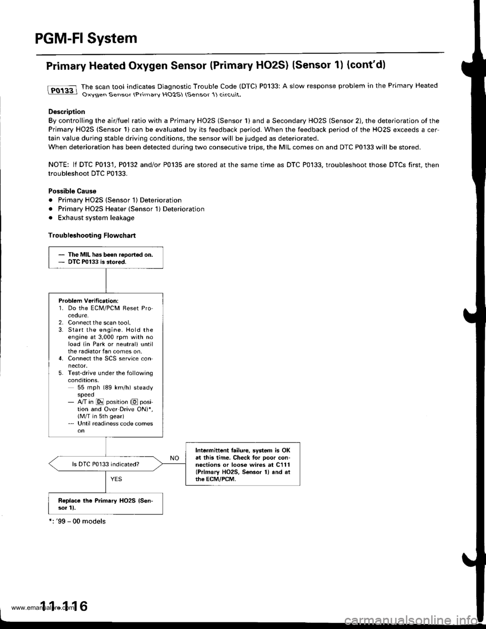
PGM-FI System
Primary Heated Oxygen Sensor (Primary HO2S) lSensor 1) (cont'd)
tFO133 lhe scan tool indicates Diagnostic Trouble Code (DTC) P0133: A slow response problem in the Primary Heated: Oxysen Sensor (Primarv HO2S (Sensor 1) circuit.
Description
By controlling the airlfuel ratio with a Primary HO2S (Sensor 1) and a Secondary HO2S (Sensor 2), the deterioration of the
Primary HO2S (Sensor 1) can be evaluated by its feedback period. When the feedback period of the HO2S exceeds a cer
tain value during stable driving conditions, the sensor will be judged as deteriorated.
When deterioration has been detected during two consecutive trips, the MIL comes on and DTC P0133 will be stored.
NOTE: lf DTC P0131, P0132 and/or P0135 are stored at the same time as DTC P0133. troubleshoot those DTCS first, then
troubleshoot DTC P0133.
Possible Cause
. Primary HO2S (Sensor 1) Deterioration
. Primary HO2S Heater (Sensor 1) Deterioration
. Exhaust system leakage
Troubleshooting Flowchart
- The MIL has b6€n reoorted on.- DTC P0133 is stored.
Problem Verilication:'1. Do the ECM/PCM Reset Procedure.2. Connect the scan tool.3. Start the engine. Hold theengine at 3,000 rpm with noload lin Park or neutrali untilthe radiator fan comes on.4. Connect the SCS service connector.5. Test-drive under the followingcondations,55 mph (89 km/h) steadyspeed- M in @ position (E position and Over Drive ON)*,(M/T in sth gear)- Until readiness code comes
Intermittent failure, system is OKat this time. Check tor poor con-nections or loose wires at C111(Primary HO2S, Sensor 1) and althe ECM/PCM.
Replace the Primary HO2S {Sen-sor 11.
1 1-1 16
www.emanualpro.com
Page 319 of 1395
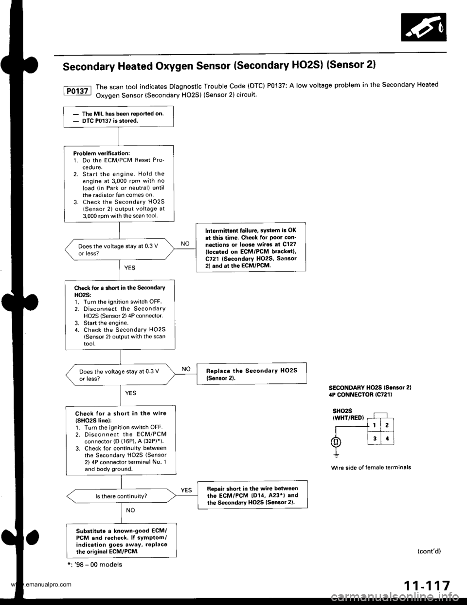
Secondary Heated Oxygen Sensor (Secondary HO2S) (Sensor 2)
The scan tool indicates Diagnostic Trouble code (DTC) P0137: A low voltage problem in the secondary Heated
Oxygen Sensor (Secondary HO2S) (Sensor 2) circuit.
SECONDARY HO2S ls.nlor 2)4P CONNECTOB lC721l
Wire side of lemale terminals
(cont'd)
11-117
The MIL hrs been reported on.DTC P0137 is stored.
Problem veritication:1. Do the ECM/PCM Reset Pro'cedure.2. Start the engine. Hold theengine at 3,000 rpm wilh no
load (in Park or neutral) untalthe radiator {an comes on,3. Check the Secondary H02S
lSensor 2) output voltage at3,000 rpm with the scan tool.
lnlermittent failure, 3ystem i5 OK
at this time. Check tor Poor con'
noction3 or loose wires at C127
{locatod on ECM/PCM bracket},C721 (Secondary HO2S, Sensor2l and at the ECM/PCM.
Does the voltage stay at 0.3 V
or less?
Check for a short in the SecondaryHO2S:1. Turn the ignition switch OFF.2. Disconnect the SecondaryHO2S lSensor 2) 4P connector.3. Start the engine.4. Check the Secondary HO25(Sensor 2) output with the scantool.
Check lor a short in the wire(SHO2S linel:1. Turn the ignition switch OFF.2. Disco n nect the ECM/PCMconnector {D (16P}, A (32P}').
3. Check for continuity betweenthe Secondary HO2S (Sensor
2i 4P connector terminal No. 1and body ground.
Reoair short in the wire b€twoen
rhe ECM/PCM |D14, 423*l and
the Secondary HO2S {Sensor 2).
Substitute a known-good ECM/PCM and rocheck. lf symptom/indication goes away, replacethe original ECM/PCM.
*: '98 - 00 modeis
www.emanualpro.com
Page 322 of 1395
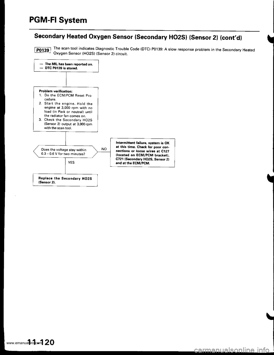
PGM-FI System
Secondary Heated Oxygen Sensor (secondary HO2SI (sensor 2l (cont,d)
lTol3al The scan tool indicates Diagnostic Trouble Code (DTC) P0139: A slow response probtem in the Secondary Heated- Uxygen Sensor (HO2S) (Sensor 2l circuit.
- The MIL has b€en reoorted on.- DTC P0139 is storad.
Probl€m ve.itication:1. Do the ECM/PCM Reset Procedure,Start the engine. Hold theengine at 3,000 rpm with noload (in Park or neutral) untilthe radiator fan comes on.Check the Secondary HO2S(Sonsor 2) output at 3,000 rpmwith the scan tool.
lntehittont failure, 3ystem is OKat this time. Chock for poor con-nections o. loose wi.es at C127(located on ECM/PCM brack€t),C721 {Secondary HO2S, Sensor 2land at the EcM/PcM.
Does the voltage stay within0.3 - 0.6 V for two minutes?
11-120
www.emanualpro.com
Page 330 of 1395
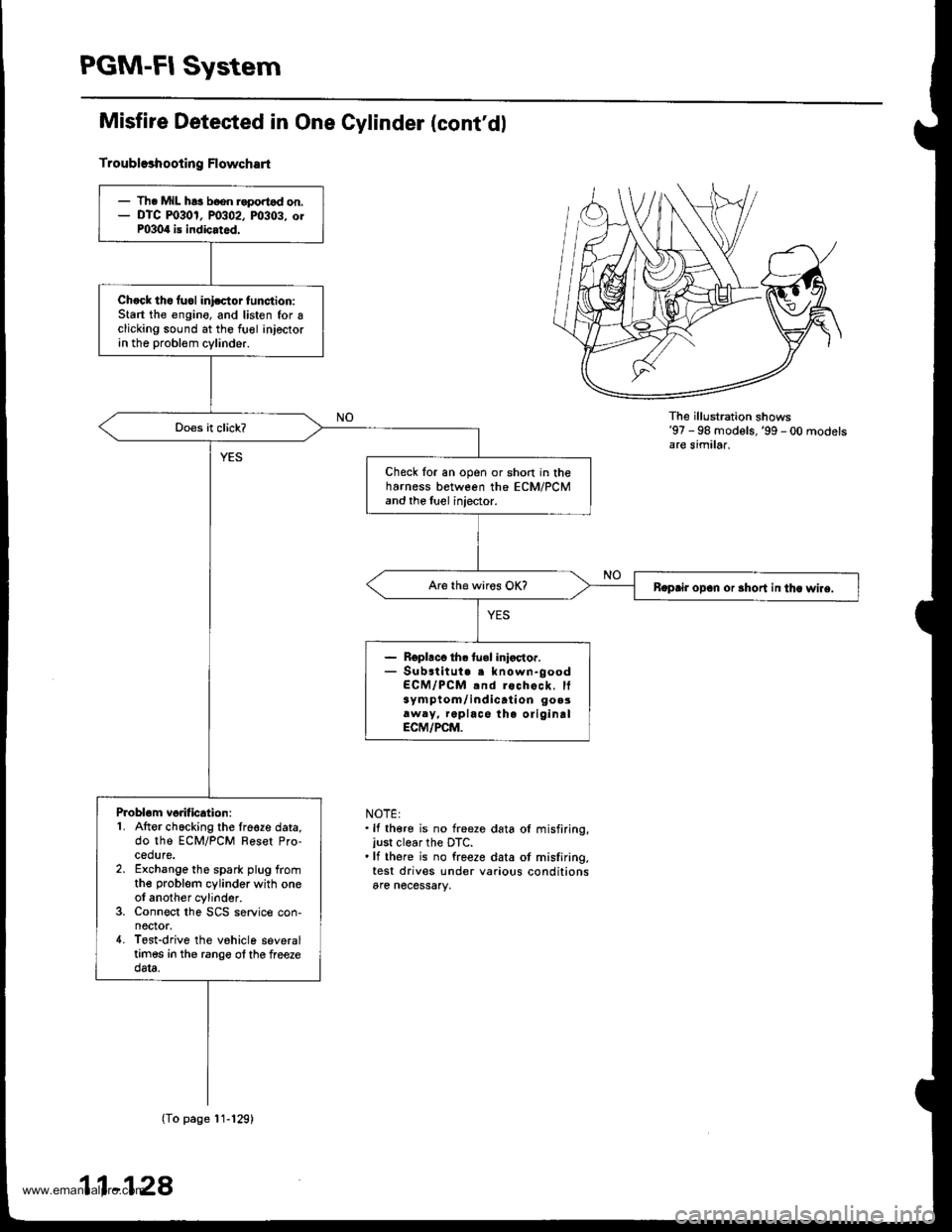
PGM-FI System
Misfire Detested in One Cylinder (cont'dl
Troubl93hooting Flowchart
The illu stration shows'97 - 98 models,'99 - 00 modelsare similar.
NOTE:.lf there is no freeze data ol misfiring,just clear the DTC..lf there is no freeze data ot misfiring,test drives under various conditionsare necessary,
- Th. MIL h!3 b6on r.portod on.- DTC m30r, P0302, m303. orP0304 is indicated.
Ch.ck tho fuol inicctor tunction:Start the engino, and listen for Iclicking sound at the fuol injectorin the probl€m cylinder.
Check for an open or short in theharness between the ECM/PCMand the luel injector.
Boprir opan or 3hort in tha wlre.
- Roplaco th. tuel inioctor.- Substitut. . known-goodECM/PCM .nd rochock. It3ym ptom/ indicati on go.3aw.y, replace the oliginalECM/PCM.
Problom vorification:1. Atter chacking the lre€ze data,do the ECM/PCM Reset Pro-cedure.2. Exchange the spark plug fromthe problem cylinder with oneol another cylinder.3. Connect the SCS service con-nector.4. Tost-drive the vohicle severaltimes in the rango ol the freezedata.
(To page'11-129)
11-128
www.emanualpro.com