cat HONDA CR-V 1997 RD1-RD3 / 1.G Workshop Manual
[x] Cancel search | Manufacturer: HONDA, Model Year: 1997, Model line: CR-V, Model: HONDA CR-V 1997 RD1-RD3 / 1.GPages: 1395, PDF Size: 35.62 MB
Page 412 of 1395
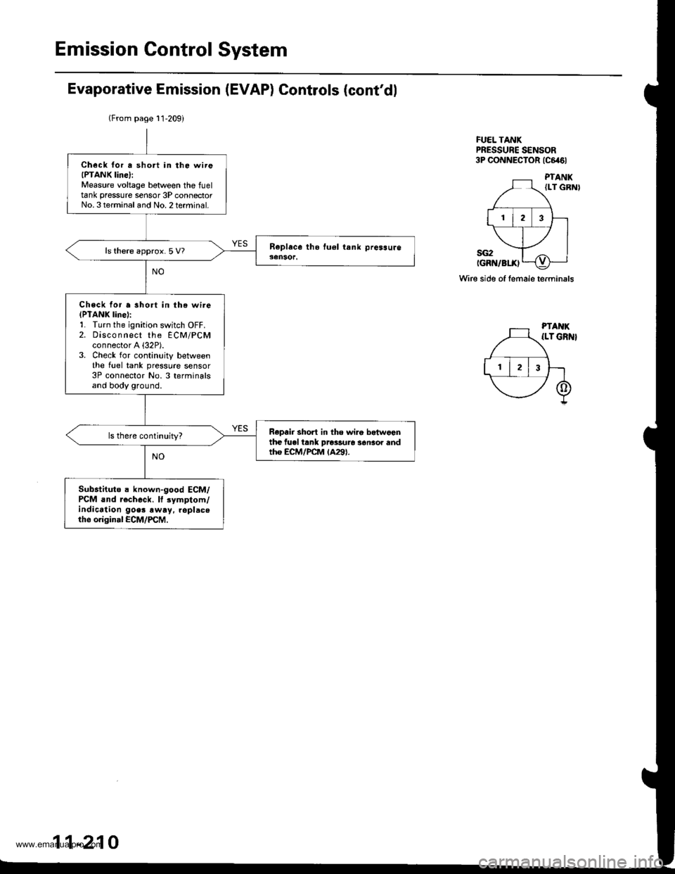
Emission Control System
Evaporative Emission (EVAP) Controls (cont'dl
FUEL TANKPRESSUNE SENSOR3P CONNECTOR tc646l
Wire side of female terminals
(From page l1'209)
Check lor a short in the wireIPTANK Iine}:Measure voltage betlveen the fueltank pressure sensor 3P connectorNo. 3terminal and No. 2terminal.
ls there approx.5 V?
Check for a short in the wire(PTANK line):1. Turn the ignition switch OFF.2. Disco n nect the ECM/PCMconnector A {32P).3. Check for continuity betweenthe fuel tank pressure sensor3P connector No. 3 terminalsand body ground.
Repair short in the wira betwgonthe fuel trnk prossure s6nsor andtho ECM/PCM lA29).
Sub.tituto a known-good ECM/PCM and r€check. lf 3ymptom/indication goer !way. replaceth6 original ECM/PCM.
11-210
www.emanualpro.com
Page 413 of 1395
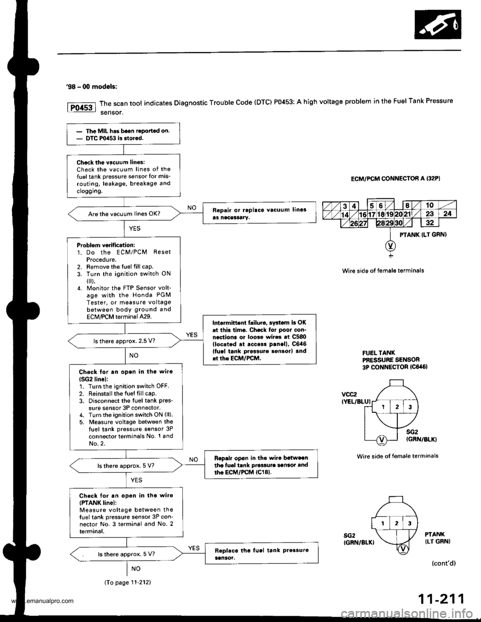
'98 - 00 modals:
The scan tool indicates Diagnostic Trouble Code (DTC) P0453: A high voltage problem in the Fuel Tank Pressure
sensor.
ECM/PCM CONNECTOR A {32PI
Wire sido ot fema16 t€rminals
FUEL TANXPf,ESSUBE SENSOR3p CONNECTOR {C6,a6l
vcc2IYEL/BLUI
sG2IGRN/BLKI
sG2(GRN/BLK}
Wire side ot female terminals
PTANKILT GRNI
(cont'd)
11-211
PTANK ILT GRN)
123
Thc MIL has b6on ropottcd on.DTC mia53 is dorcd.
Ch6ck tho vacuum linos:Check the vacuum lines of the
fuel tank pressure sensor lor mis-
routing, leakage, breakage and
cloggrng.
Are the vacuum lines OK?
Problorn verif ication:1. Do the ECM/PCM ResetProcedute.2. Remove the fuel fill cap.
3. Turn the ignition switch ON
{[).4. Monitor the FTP Sensor volt-age with the Honda PGM
Tester, or measure voltagebetween body ground and
ECM,PCM terminal429.Intarmittent tailuro, sv3iom b OKat this timo. Chock for poor con-nection3 or loo$ wire3 at C580(locstod .t .cc$r p.nell, C6a6(fucl tank pros3ure son3orl and.t the ECM/FCM.
ls there approx. 2.5 V?
Check lor an open in tho wiro
lSG2lin6l:1. Turn the ignition switch OFF.
2. R6installthe Iuel fill cap.3. Disconnect the Iu6l tank pres_
sure sensor 3P connector,4. Turn the ignition switch ON (ll).
5. M€asure voltago between thetuel tank pressure sensor 3P
connector terminals No. '! andNo.2.
Replir op€n in th. wi.c b€{weentha fuel tank Dio'sute sansot andtho EC|,/PCM {Cl8}.ls there approx. 5 V?
Ch€ck for an opon in tho wiro(PTANK linel:Measure voltage between thefuel tank pressure sensor 3P con-nector No. 3 terminal and No. 2terminal.
ls there approx. 5 V?
\To page 11-212)
www.emanualpro.com
Page 414 of 1395
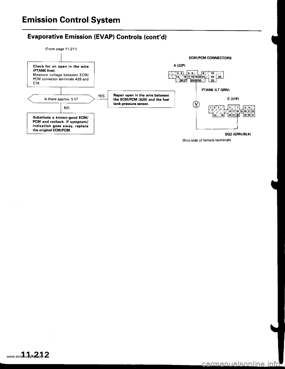
Emission Control System
Check fo. an open in the wire(PTANK linel:Measure voltage between ECM/PCM connector terminals A29 andc18.
Ropair open in the wire betweonthe ECM/PCM {A291 and tho fuoltank pressule 3ensor.
ls there approx.5 V?
Substitute a known-good ECM/PCM and recheck. lf symptom/indication goes away, r€placetho originrl ECM/PCM.
Evaporative Emission (EVAP) Controls (cont'dl
(From page 11,211)
ECM/PCM CONNECTORS
SG2 (GRN/BLK}
Wire side of temale terminals
11-212
-
PTANK {LT GRNI
www.emanualpro.com
Page 415 of 1395
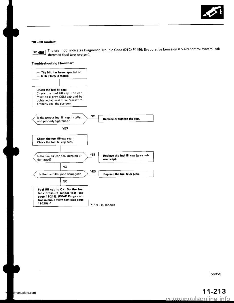
'98 - 00 models:
The scan tool indicates Diagnostic Trouble code (DTC) P1456: Evaporative Emission (EVAP) control system leak
detected {fuel tank system).
Troubleshooting Flowchart
- The MIL has been reported on.- DTC P1456 is stored.
Check the fuel fill cap:Check the fuel fill cap (the caP
must be a gray OEM cap and be
tightened at least three "clicks" toproperly seal the system)-
ls the proper fuel fill cap installed
and properly tightened?Replace or tighton the cap.
Check the lueltill cap seal:
Check the fuel fill cap seal.
Replace the luelfiller pipe.ls the tuel filler pipe damaged?
Fuel till caD is OK. Do the luel
tank pressure Sensor test (see
page 11-2111. (EVAP Purge con-
trol solenoid valve t€sl (see Page11-2151.1r':'99 - 00 models
(cont'd)
11-213
www.emanualpro.com
Page 417 of 1395
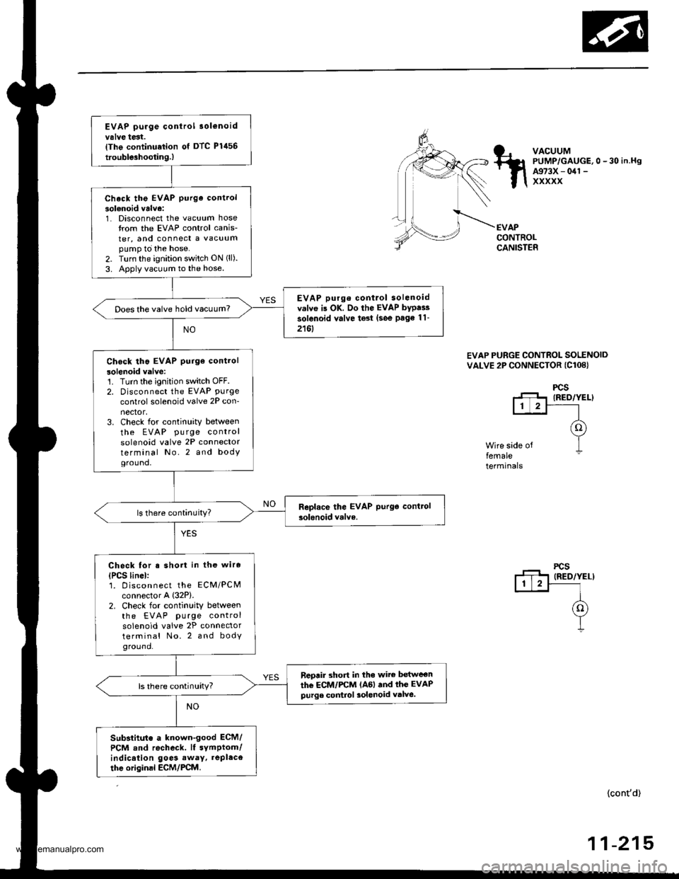
EVAP purge control 3ol€noidvalve test.{Tho continu.tion of DTC Plil56
trouble3hootin9.)
Check the EVAP purge control
solenoid valve:1. Disconnect the vacuum hosetrom the EVAP control canis-
ter, and connect a vacuumpump to the hose.2. Turn the ignition switch ON (ll).
3. Apply vacuum to the hose.
EVAP purge contlol solenoidv.lvo is OK. Do the EVAP bypai3
solenoid valve test (see Page 11-
2161
Does the valve hold vacuum?
Check tho EVAP purge control
solenoid valve:'t. Turn the ignition switch OFF.2. Disconnect the EVAP Purgecontrol solenoid valve 2P con-nector,3. Check for continuity between
the EVAP pu rge controlsolenoid valve 2P connectorterminal No.2 and bodYground,
Check for s short in the wire
{PCS linel:1. D iscon nect the ECM/PCMconnector A {32P).2. Check for continuity betweenthe EVAP purge controlsolenoid valve 2P connectorterminal No. 2 and bodyground.
neprir short in tho wite bot$reon
the ECM/FCM lAGl and thc EVAPpurge control 3olenoid valve.ls there continuity?
Substitut€ a known-good ECM/
PCM and recheck. lf symptom/indication goe3 away. repl.ce
thc originsl ECM/PCM.
VACUUMPUMP/GAUGE,0 - 30 in.HgA973X - 041 -
xxxxx
EVAPCONTROLCANISTER
EVAP PURGE CONTROL SOLENOIDVALVE 2P CONNECTOR (Cl08}
Wire side offemaleterminals
(cont'd)
-21511
www.emanualpro.com
Page 420 of 1395
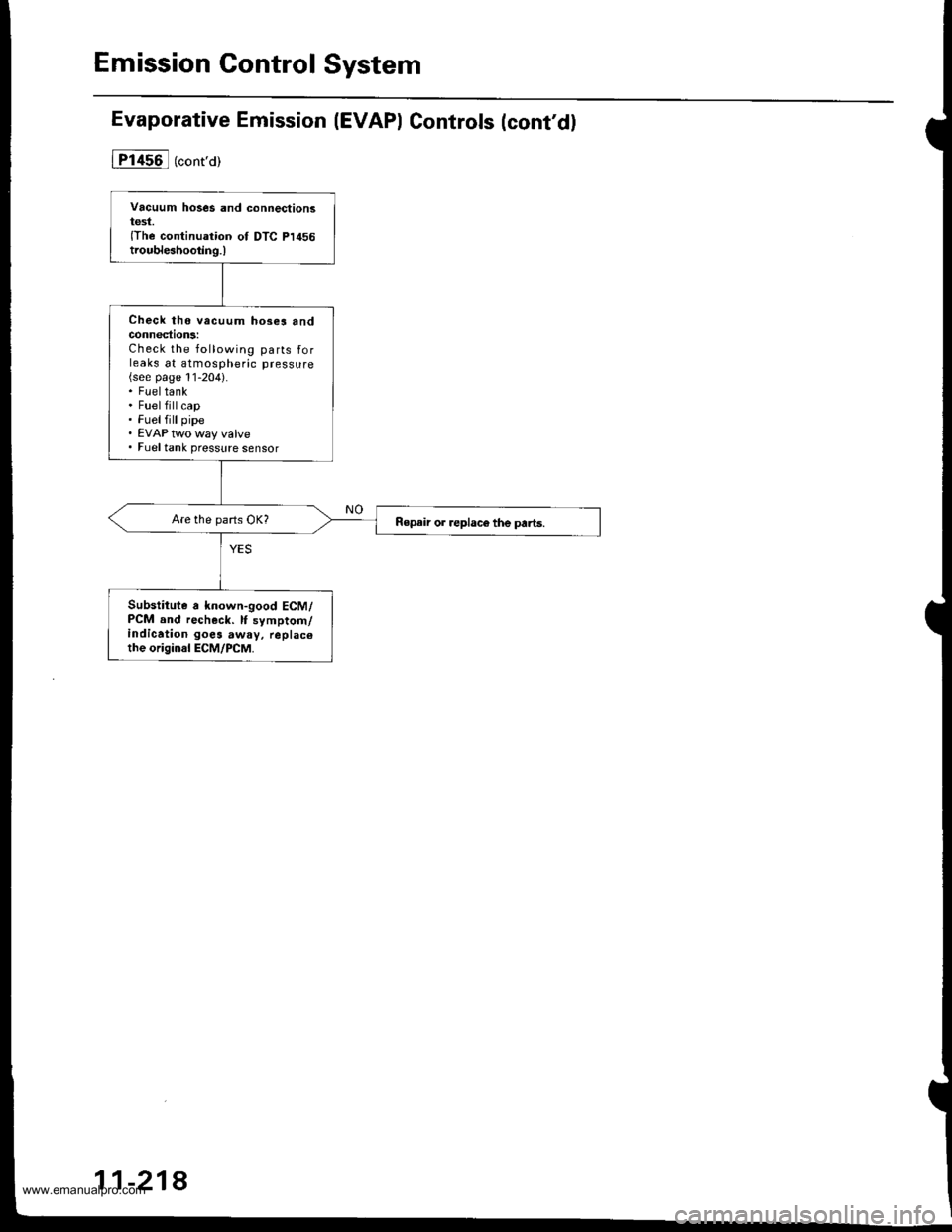
Emission Control System
Evaporative Emission IEVAPI Controls (cont'd)
lTi,t56l ("onto)
Vacuum hoses and connectionstelit.(The continuarion of DTC P1456troubleshooiing.l
Check the vacuum ho3es andconnect|ons:Check the following parts forleaks at atmospheric p ressu re{see page 11-204).. Fueltank. Fuel fill cap. Fuelfill pipe. EVAP two way valve. Fueltank pressure sensor
Repair or replaco the parts.
Substitute a known-good ECM/PCM and recheck. lf symptom/indication goes away, replac€the original ECM/PCM.
11-218
www.emanualpro.com
Page 421 of 1395
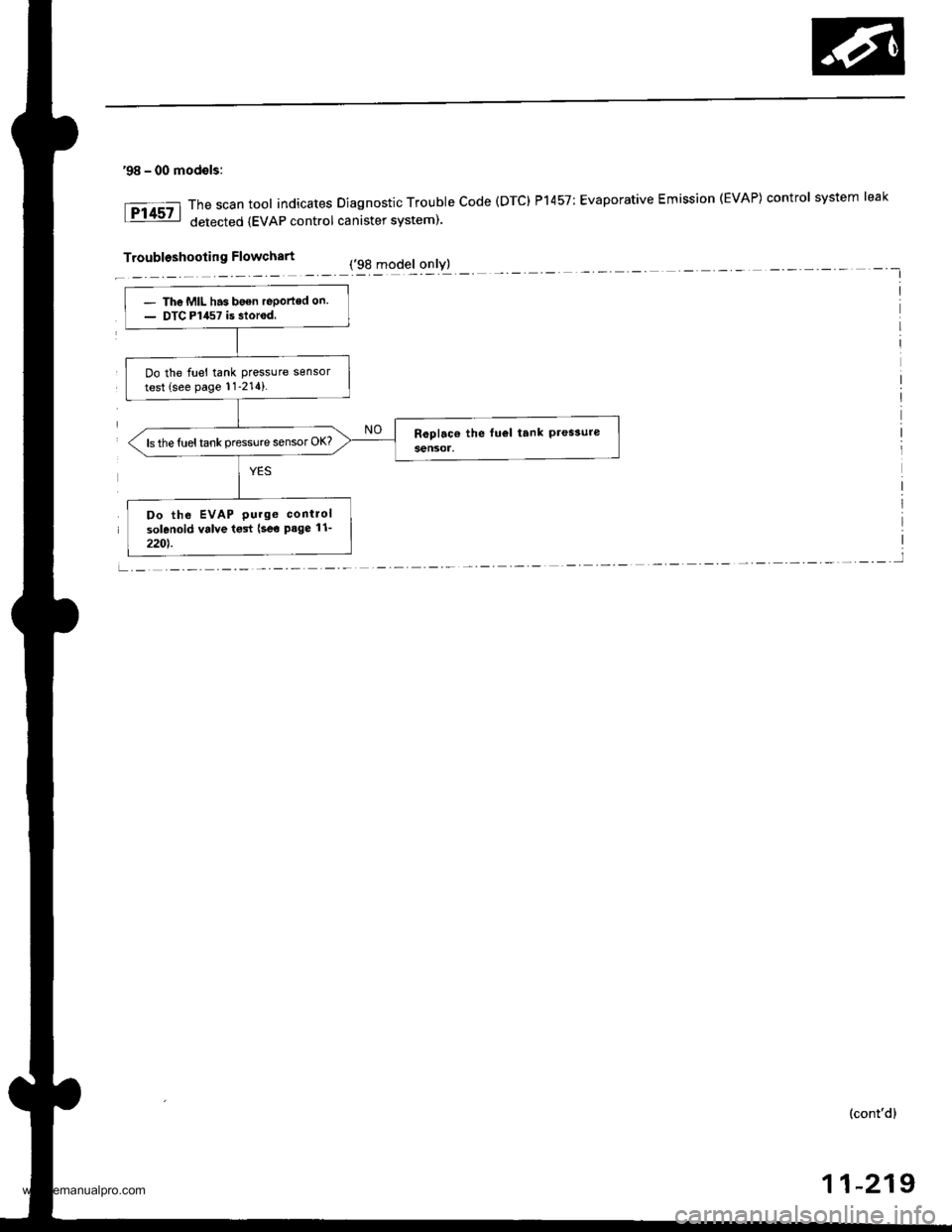
'98 - 00 mod€ls:
The scan tool indicates Diagnostic Trouble code (DTc) P1457: Evaporative Emission (EVAP) Control system leak
detected (EVAP control canister system).
Troubl6shooting Flowchart('98 model only)_]
I
- The MIL has been rePorted on.- DTC P1,157 is storod.
Do the fuel tank Pressure sensor
test {see page 11-214).
ls the {ueltank pressure sensor OK?
Do the EVAP Purge contlol
solenoid valve test lsea Page 1l_
220t.
(cont'dl
11-219
www.emanualpro.com
Page 423 of 1395
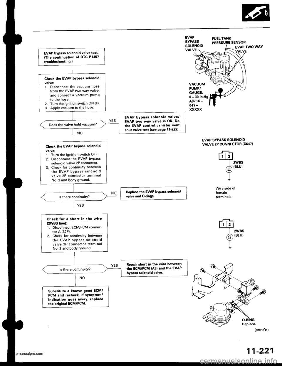
EVAP bypass solenoid valv€ test.
{The continuation of DTC P1457
troubleshooting.l
Check the EVAP bypass 3olenoid
1. Disconnect the vacuLlm hose
from the EVAP two way valve,
and conned a vacuum PUmPto the hose.2. Turn the ignition switch ON (ll).
3. Apply vacuum to the hose
EVAP bvpas3 30lsnoid vrlvo/
EVAP two way v.lve is OK. Do
the EVAP control canisler vent
3hut v.lve te3l (see Psge11'2221.
Does the valve hold vacuum?
Ch6ck the EVAP byp.ss solenoid
'1. Turn the ignition switch OFF
2. Disconnect the EVAP bypass
solenoid valve 2P connector.
3. Check {or continuity between
the EVAP bypass soleno id
valve 2P connector termlnal
No. 2 and body ground
ReDlace the EVAP bypass 3olenoid
valve and O-rings.
Check for a short in lhe wire
{2WBS linel:1. Disconnect ECM/PCM connec
tor A (32P).
2. Check lor continuity betlveenthe EVAP bypass soleno id
valve 2P connector termrnalNo. 2 and body ground.
Rcpsir short in th. wire bgtwoen
the EcM/PCtrl lA3l lnd the EVAP
bypa$ solenoid valvo.ls there continuitY?
Sub3tiiute . known'good ECM/
PCM End recheck. lI sYmptom/
indication goe3 away, tePlace
the original ECM/PCM.
EVAPBYPASSFUELTANKPRESSUBE SENSORSOLENOIDVALVEEVAP TWO WAY
VALVE
VACUUMPUMP/GAUGE,0-30 in.HgA973X -
041 -
xxxxx
EVAP AYPASS SOLENOID
VALVE 2P CONNECTOR (C647}
q
@)
T
t.'-+lt1t?l
| 2wBs
(d1 terul
Y-L
Wire side offemaleterminals
2WBS(BLU}
(cont'd)
11-221
www.emanualpro.com
Page 426 of 1395
Emission Control System
Evaporative Emission (EVAP) Controls (cont,dl
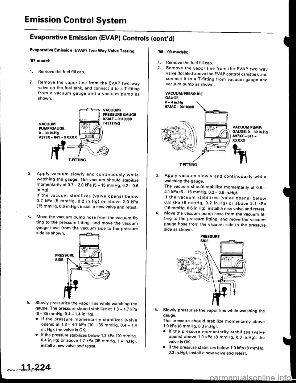
Evaporative Emission (EVAP) Two Way Valve Testing
'97 model:
1. Remove the fuelfill cap.
2. Remove the vapor Iine from the EVAP two wayvalve on the fuel tank, and connect it to a T_fittingfrom a vacuum gauge and a vacuum pump asshown.
VACUUM,/PRESSURE GAUGEotJAz - 001 rDoBT-FITTINGVACUUMPUMP/GAUGE,0 - 30 in.HgA973X-041-XXXXX
3. Apply vacuum slowly and continuouslv whilewatching the gauge. The vacuum should stabilizemomentarily at 0.7 - 2.0 kpa (5 - 1S mmHg, 0.2 _ 0.6in.Hg).
lf the vacuum stabilizes (valve opens) below0.7 kPa (5 mmHg,0.2 in,Hg) or above 2.0 kpa(15 mmHg, 0.6 in.Hg), install a new valve and retest.
4.Move the vacuum pump hose from the vacuum fit_ting to the pressure fitting, and move the vacuumgauge hose from the vacuum side to the pressureside as shown.
PiESSURESIDE
5. Slowly pressurize the vapor line while watching thegauge. The pressure should stabilize at 1.3 - 4.7 kpa(0 - 35 mmHg, 0.4 - 1.4 in.Hg).. lf the pressure momentarily stabilizes (valve
opens) at 1.3 - 4.7 kpa (10 - 35 mmHg, 0.4 _ 1.4in. Hg), the valve is OK.. lf th6 pressure stabilizes below 1.3 kpa fio mmHg,0.4 inrHg) or above 4.7 kpa (35 mmHg, 1.4 in.Hg),install a new valve and retest.
T-FITTING
11-224
.98 - 0O models:
1. Remove the fuel fill cap.2. Remove the vapor line from the EVAP two wayvalve {located above the EVAP control canister). andconnect it to a T-fitting from vacuum gauge andvacuum pump as shown.
VACUUM/PRESSUFE
VACUUM PUMP/GAUGE,0 - 30 in.HgA973X - 041 -
xxxxx
5.
Apply vacuum slowly and continuously whilewatching the gauge.
The vacuum should stabilize momentarily at O.g _
2.1 kPa (6 - 16 mmHg, 0.2 - 0.6 in.Hg).lf the vacuum stabilizes (valve opens) below0.8 kPa (6 mmHg, 0.2 in.Hg) or above 2.1 kpa(16 mmHg, 0.6 in.Hg), install a new valve and retest.Move the vacuum pump hose from the vacuum fit-ting to the pressure fitting. and move the vacuumgauge hose from the vacuum side to the pressure
side as shown.
Slowly pressurize the vapor line while watching thegauge.
The pressure should stabilize momentarilv above1.0 kPa (8 mmHg, 0.3 in.Hg).a lf the pressure momentarily stabilizes (valve
opens) above 1.0 kPa (8 mmHg. 0.3 in.Hg), thevalve is OK.. lf the pressure stabilizes below ,|.0 kpa {g mmHg.0.3 in.Hg), install a new valve and retest.
T-FITTING
www.emanualpro.com
Page 436 of 1395
Flywheel
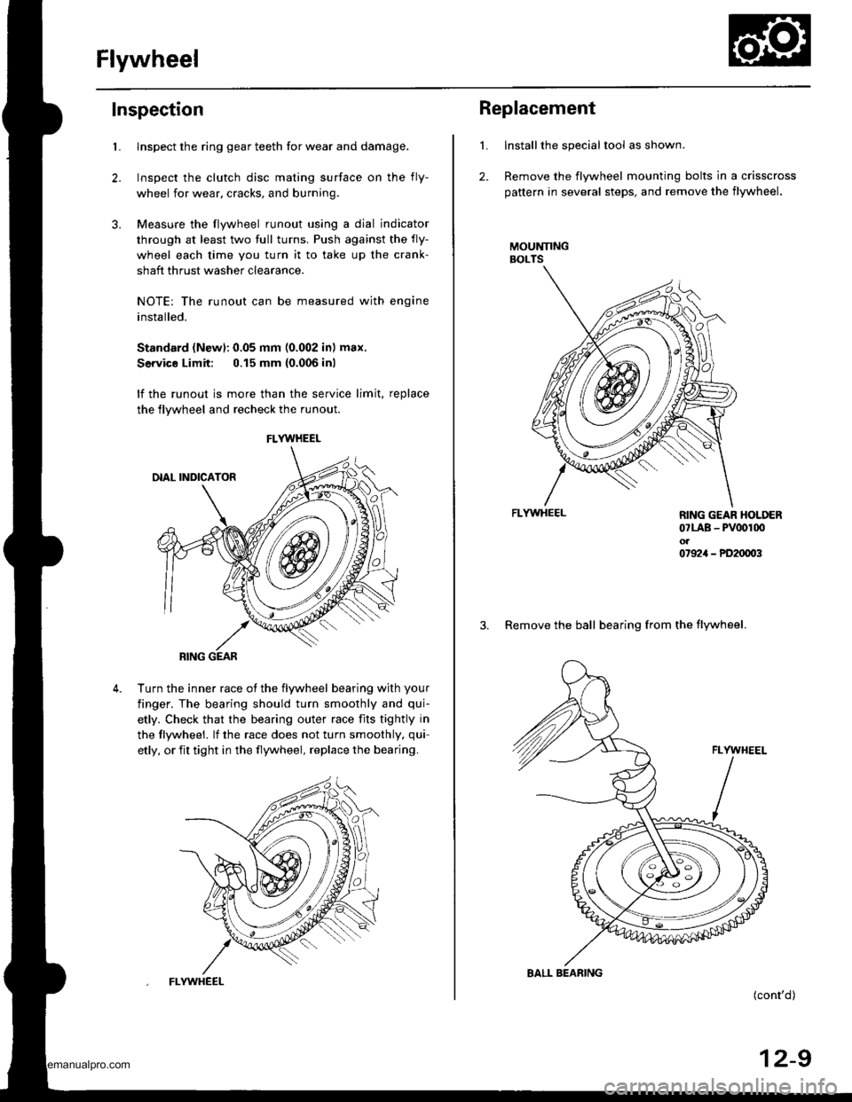
Inspection
2.
3.
Llnspect the ring gear teeth for wear and damage.
Inspect the clutch disc mating surface on the fly-
wheel for wear, cracks, and burning
Measure the flywheel runout using a dial indicator
through at least two full turns. Push against the fly-
wheel each time you turn it to take up the crank-
shaft thrust washer clearance.
NOTE: The runout can be measured with engine
installed.
Standard (Newl: 0.05 mm (0.002 in) max.
Service Limit: 0.15 mm {0.006 inl
lf the runout is more than the service limit, replace
the flywheel and recheck the runout
Turn the inner race ot the flywheel bearing with your
finger. The bearing should turn smoothly and qui-
etly. Check that the bearing outer race fits tightly in
the tlywheel. lf the race does not turn smoothly, qui-
etly, or fit tight in the flywheel, replace the bearing.
FLYWHEEL
RING GEAR
FLYWHEEL
L
2.
Replacement
Installthe special tool as shown.
Remove the flywheel mounting bolts in a crisscross
pattern in several steps, and remove the flywheel.
MOUNNNGBOLTS
FLYWHEEL
(cont'd)
12-9
RING GEAR HOLDER07LAB - PV00r00ol07924 - PD20003
3. Remove the ball bearing from the flywheel.
BALL BEARING
www.emanualpro.com