INJECTOR HONDA CR-V 1997 RD1-RD3 / 1.G User Guide
[x] Cancel search | Manufacturer: HONDA, Model Year: 1997, Model line: CR-V, Model: HONDA CR-V 1997 RD1-RD3 / 1.GPages: 1395, PDF Size: 35.62 MB
Page 326 of 1395
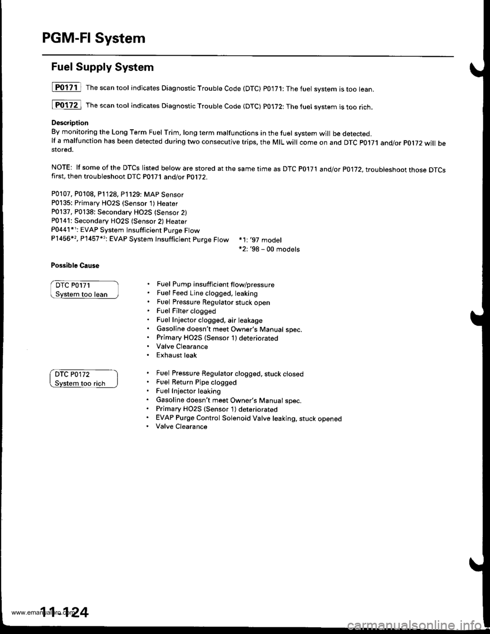
PGM-FI System
Fuel Supply System
[POliil The"""ntool indicates Diagnostic Troubte Code (DTC) p0'171:Thefuet system istoo lean.
[Fo17ZJ rh""""ntool indicates Diagnostic Troubte code {DTc) p0172:Thefuel svstem istoorich.
Description
By monitoring the Long Term Fuel rrim, long term malfunctions in the fuel system will be detected.lf a malfunction has been detected during two consecutive trips, the MIL will come on and DTc p0171 and/or pol72 will bestored.
NOTE: lf someof the DTCS listed below are stored atthesametimeas DTC P017'l and/or p0172, troubleshoot those DTcsfirst, then troubleshoot DTC P0171 and/or PO1i2.
P0107, P0108, P1128, P'1129: MAP Sensor
P0135: Primary HO2S (Sensor 1)Heater
P0137, P0138: Secondary HO2S {Sensor 2)P0141: Secondary H02S (Sensor 2) Heater
P0441*r: EVAP System lnsufficient Purge FtowP1456*,, P'l457 *?i EVAP System Insufficient purge Ftow
Possible Cause
DTC P0171
too lean
*1: '97 model*2: '98 - 00 models
Fuel Pump insufficient flow/pressure
Fuel Feed Line clogged. leaking
Fuel Pressure Regulator stuck openFuel Filter clogged
Fuel Injector clogged, air leakage
Gasoline doesn't meet Owner's Manual spec.Primary HO2S (Sensor 1) deteriorated
Valve Clearance
Exhaust leak
Fuel Pressure Regulator clogged, stuck closedFuel Return Pipe clogged
Fuel Injector leaking
Gasoline doesn't meet Owner's Manual spec.Primary H02S (Sensor 1) deteriorated
EVAP Purge Control Solenoid Valve leaking, stuck openedValve Clearance
DTC P0172
flch
11-124
www.emanualpro.com
Page 329 of 1395
![HONDA CR-V 1997 RD1-RD3 / 1.G User Guide
Misfire Detected in One Cylinder
Ipffi1] Thescantoot indicates Diagnostic Trouble Code (DTC) P0301: Cylinder 1 misfire detected.
lF03O2l 16".""n toot indicates Diagnostic Trouble Code (DTC) P0302; Cy HONDA CR-V 1997 RD1-RD3 / 1.G User Guide
Misfire Detected in One Cylinder
Ipffi1] Thescantoot indicates Diagnostic Trouble Code (DTC) P0301: Cylinder 1 misfire detected.
lF03O2l 16".""n toot indicates Diagnostic Trouble Code (DTC) P0302; Cy](/img/13/5778/w960_5778-328.png)
Misfire Detected in One Cylinder
Ipffi1] Thescantoot indicates Diagnostic Trouble Code (DTC) P0301: Cylinder 1 misfire detected.
lF03O2l 16".""n toot indicates Diagnostic Trouble Code (DTC) P0302; Cylinder 2 misfire detected.
I P0303 | fne scan tool indicates Diagnostic Trouble Code (DTC) P0303: Cylinder3 misfire detected.
lF0il04l 16" ""un tool indicates Diagnostic Trouble Code (DTC) PO3O4: Cylinder 4 misfire detected
Description
Misfire detection is accomplished by monitoring the crankshaft speed with the crankshaft speed fluctuation (CKF) sensor
which is attached to the crankshaft.
lf misiiring strong enough to damage the catalyst is detected, the MIL will blink during the time of its occurrence. and DTC
P0301, P0302, P0303 and/or P0304 will be stored. Then, after the misfire has ceased, the MIL will come on.
lf misfiring that increases emissions is detected during two consecutive driving cycles. the MIL will come on, and DTc
P0301, P0302, P0303 and/or P0304 will be stored.
NOTE: lJ some of the DTcs listed below are stored at the same time as a misfire DTc, troubleshoot those DTcs first, then
troubleshoot the misfire DTC.
P0107, P0108, P'n2a, P1129t MAP sensor
Po'17 'l , P0112t Fuel suPP|Y system
P0441: EVAP insufficient Purge flow
P1336, P1337: CKF sensor
P1359, Pl361, P1362: TDC sensor
Pl381, P1382: CYP sensor
Possible Cause
. Fuel injector clogging, fuel leakage, air leakage
. Fuel injector circuit open or shorted
. Spark plug carbon deposits, fouling, malfunction
. lgnition wires open, leaking
. Distributor malfunction
. Compression low
. Valve clearance out of specification
(cont'd)
11-127
www.emanualpro.com
Page 330 of 1395
PGM-FI System
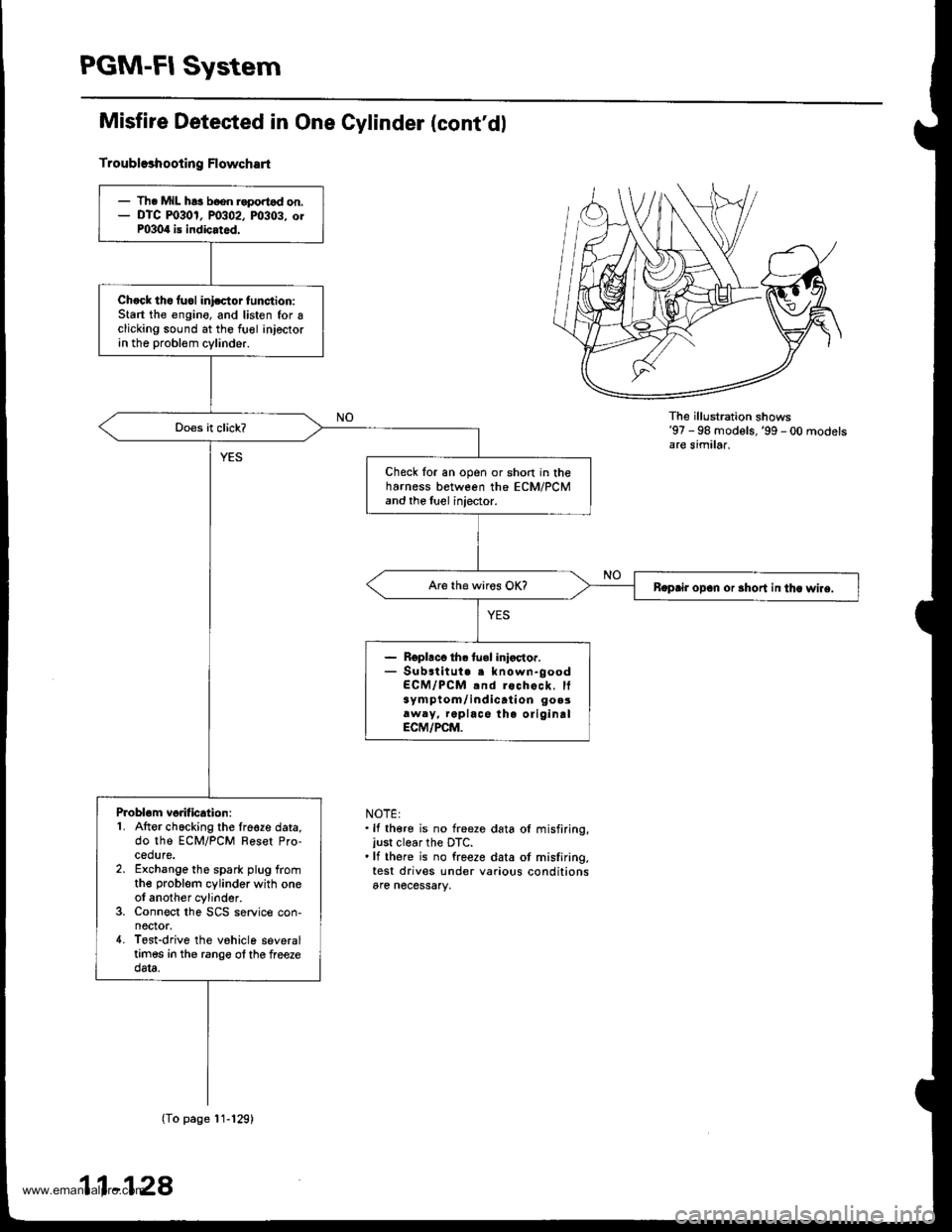
Misfire Detested in One Cylinder (cont'dl
Troubl93hooting Flowchart
The illu stration shows'97 - 98 models,'99 - 00 modelsare similar.
NOTE:.lf there is no freeze data ol misfiring,just clear the DTC..lf there is no freeze data ot misfiring,test drives under various conditionsare necessary,
- Th. MIL h!3 b6on r.portod on.- DTC m30r, P0302, m303. orP0304 is indicated.
Ch.ck tho fuol inicctor tunction:Start the engino, and listen for Iclicking sound at the fuol injectorin the probl€m cylinder.
Check for an open or short in theharness between the ECM/PCMand the luel injector.
Boprir opan or 3hort in tha wlre.
- Roplaco th. tuel inioctor.- Substitut. . known-goodECM/PCM .nd rochock. It3ym ptom/ indicati on go.3aw.y, replace the oliginalECM/PCM.
Problom vorification:1. Atter chacking the lre€ze data,do the ECM/PCM Reset Pro-cedure.2. Exchange the spark plug fromthe problem cylinder with oneol another cylinder.3. Connect the SCS service con-nector.4. Tost-drive the vohicle severaltimes in the rango ol the freezedata.
(To page'11-129)
11-128
www.emanualpro.com
Page 331 of 1395
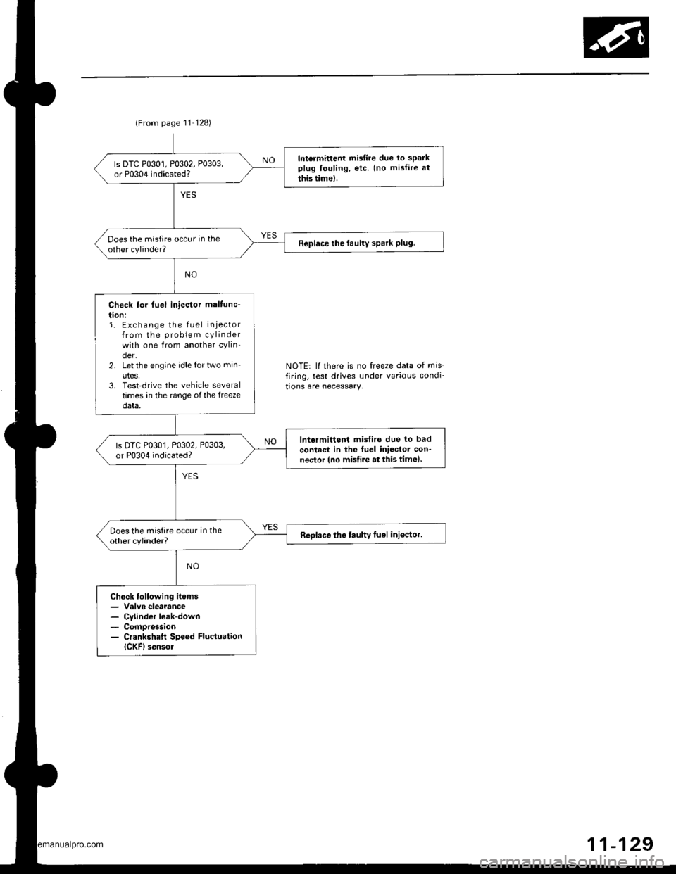
(From page 11-128)
lntormittent misfire due lo sparkplug fouling, etc. (no mislire at
this tim€).
ls DTC P0301, P0302, P0303,or P0304 indicated?
ooes the misfire occur in theother cylinder?Replace the faulty spark Plug.
Check lor fuel iniector maltunc-
t|on:1. Exchange the fuel injectorfrom the problem cylinderwith one from another cylin-der.2. Let the engine idle for two min
utes.3. Test'drive the vehicle severaltimes in the range of the freezedata,
lntermittent misfiro due lo bad
contrct in the fuel iniector con-nector {no misfire at this time).
ls DTC P0301, P0302, P0303,or P0304 indicated?
Does the misfire occur in theother cylinder?Replace lhe faulty luel inlector.
Check following items- Valvo clearance- Cvlinder l€ak-down- Compression- Crsnkshaft Speed FluctuationICKF) sensol
NOTE: lf there is no freeze data of misfiring, test drives under various condi_
tions are necessary.
11-129
www.emanualpro.com
Page 380 of 1395
Fuel Supply System
System Description
The fuel supply system consists of a fuel tank, in-tank
high-pressure fuel pump. PGM-Fl main relay, fuel filter,
fuel pressure regulator, fuel injectors, and fuel delivery
and return lines. This system delivers pressure-regulat-
ed fuel to the fuel injectors and cuts the fuel delivery
when the engine is not running.
Fuel Pressure
Relieving
Before disconnecting fuel pipes or hoses, release pres-
sure from the system by loosening the 12 mm banjo
bolt on the too of the fuel filter.
Do not smoke while working on the fuel system.
Ke€p open flames or sparks away from your work
area,
Be sure to relieve fuel pressure while the ignition
switch is off.
Write down the frequencies for the radio's preset
buttons.
Disconnect the battery negative cable from the bat-
tery negative terminal.
Remove the fuel fill cap.
Use a box end wrench on the 12 mm banjo bolt at
the fuel filter while holding the fuel filter with anoth-
er wrench.
Place a rag or shop towel over the '12 mm banjo bolt.
Slowly loosen the 12 mm banjo bolt one complete
rurn 12 mm BANJoBOLT
1.
SHOP TOWEL
NOTE: Replace the washers whenever the 12 mm
banio bolt is loosened or removed.
11-178
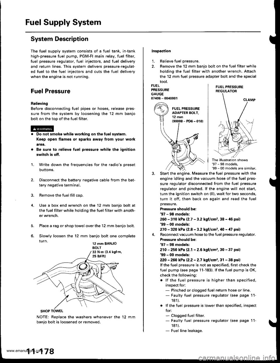
Inspection
1, Relieve fuel pressure.
2. Remove the 12 mm banjo bolt on the fuel filter while
holding the fuel filter with another wrench. Attach
the 12 mm fuel pressure adapter bolt and the special
tool.
FUEL PRESSUREREGULATON
FUELPRESSUREGAUGE07406 - 0040001
The illustration shows'97 - 98 models,'99 - 00 models are similar.
Start the engine. Measure the fuel pressure with the
engine idling and the vacuum hose of the fuel pres-
sure regulator disconnected from the fuel pressure
regulator and pinched. lf the engine will not start,
turn the ignition switch on (ll), wait for two seconds,
turn it off, then back on again and read the fuel
pressure.
Pressure should be:'97 - 98 mod€ls:
260 -31O kPa 12.7 - 3.2 kgf/cm,, 38 - 46 psil'99 - 0O models:
270 - 32O kPa Q.A - 3.2 kgf/cm'�, ifo - /U psil
Reconnect vacuum hose to the fuel pressure regulator.
Prgs3ure should be:'97 - 98 models:
210 - 25O kPa 12.1- 2.6 kgf/cm'�, 30 - 37 psi)'99 - 00 models:
22O -26iJ kPa 12.2 - 2.7 kgt/cm'�, 31 - 38 psi)
lf the fuel pressure is not as specified, first check the
fuel pump (see page 11- 183). lf the fuel pump is OK,
check the following:
. lf the fuel pressure is higher than specified,
inspect for:- Pinched or clogged fuel return hose or line.- Faulty fuel pressure regulator (see page 11-
181).
. lf the fuel pressure is lower than specified. inspect
for:- Clogged fuel filter.- Faulty fuel pressure regulator (see page 11-
1811.- Fuel line leakage.
www.emanualpro.com
Page 381 of 1395
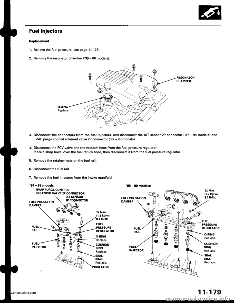
Fuel Injectors
R6placomoni
1. Relieve the fuel pressure (see page 11-178).
2. Remove the resonato. chamber ('99 - 00 models).
O.RINGBeplace.
Disconnect the connectors from the fuel injectors, and disconnect the IAT sensor 2P connector ('97 - 98 models) and
EVAP purge control solenoid valve 2P conn€ctor ('97 - 98 models),
Disconnect the PCV valve and the vacuum hose from the fuel pressure regulator.
Place a shop towel over the fuel return hose, then disconnect it from the fuel pressure regulator.
Remove the retainer nuts on the fuel rail.
Disconnect the fuel rail.
7, Remove the fuel injectors from the intake manifold.
'97 - 98 model3:
EVAP PURGE CONTROLSOLENOID VALVE 2P CONNECTORIAT SENSOR
FUEL PULSATION2P CONNECTOR
12 N.m{1.2 kgt'm,8.7 tbtft)
FUELPRESSUREREGULATOR
O.RING
FUELPRESSUREREGULATOR
CUSHION
O.RINGReplace.
CUSHIONRINGReplace.
SEALRINGReplace.
Replace.
SEALRINGReplace.
S
11-179
www.emanualpro.com
Page 382 of 1395
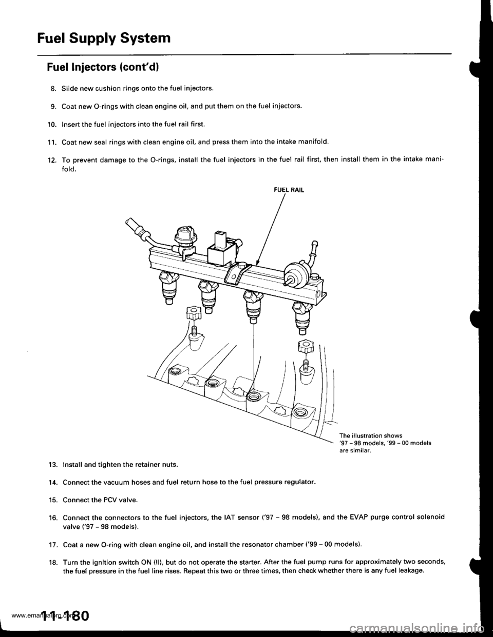
Fuel Supply System
Fuel Injectors {cont'dl
8. Slide new cushion rings onto the fuel injectors.
9, Coat newO-ringswith clean engine oil,and putthem onthefuel iniectors.
'10. lnsert the fuel injectors into the fuel rail first.
11. Coatnewseal ringswithclean engineoil,and press them into the intake manifold
12. To prevent damage to the O-rings, install the fuel injectors in the fuel rail first, then install them in the intake mani-
fold.
FUEL RAIL
The ill!stration shows'97 -98 models,'99 - 00 modelsare similar.
13. lnstall and tighten the retainer nuts.
14. Connect the vacuum hoses and fuel return hose to the fuel pressure regulator.
15. Connect the PCV valve.
16. Connect the connectors to the fuel injectors, the IAT sensor ('97 - 98 models), and the EVAP purge control solenoid
valve {'97 - 98 models).
Coat a new O-ring with clean engine oil, and install the resonator chamber ('99 - 00 models).
Turn the ignition switch ON (ll), but do not operate the starter. After the fuel pump runs for approximately two seconds,
the fuef pressure in the fuel line rises. Repeat this two or three times, then check whether there is any fuel leakage.
11.
18.
1 1-180
www.emanualpro.com
Page 389 of 1395
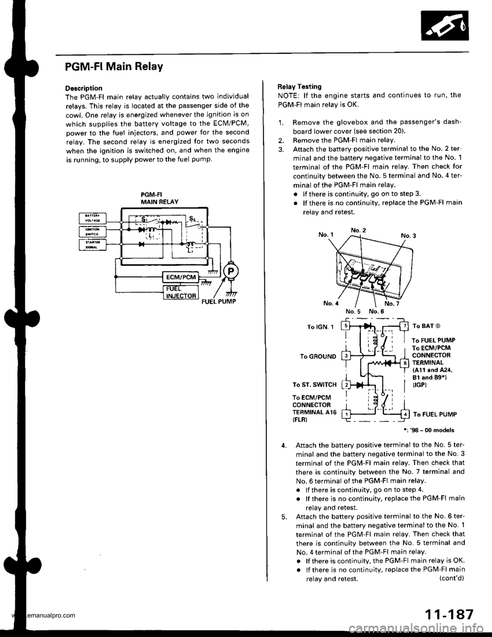
PGM-FI Main Relay
Description
The PGM-Fl main relav actuallv contains two individual
relays. This relay is located at the passenger side of the
cowl. One relay is energized whenever the ignition is on
which supplies the battery voltage to the ECM/PCM,
power to the fuel injectors, and power for the second
relay. The second relay is energized for two seconds
when the ignition is switched on, and when the engine
is running, to supply power to the fuel pump
PGM.FIMAIN RELAY
Belay Testing
NOTE: lf the engine starts and continues to run, the
PGM-FI main relay is OK.
1. Remove the glovebox and the passenger's dash-
board lower cover (see section 20).
2. Remove the PGM-FI main relay
3. Aftach the battery positive terminal to the No. 2 ter-
minal and the battery negative terminal to the No. 1
terminal of the PGM-Fl main relay. Then check for
continuity between the No. 5 terminal and No. 4 ter-
minal of the PGM-FI main relay
. lfthere is continuity, go on to step 3.
. lf there is nocontinuity, replacethe PGM-Fl main
relav and retest.
No.2
To lGN. 1
To GROUND
To ST. SWITCH
To ECM/PCMCONNECTORTERMINAL A16(FLR)
To BAT O
To FUEL PUMPTo ECM/PCMCONNECTORTERMINAL(411 and A24,Bl .nd Bgal(IGP)
To FUEL PUMP
98 - 00 models
Attach the batterv Dositive terminal to the No. 5 ter-
minal and the battery negative terminal to the No. 3
termjnal of the PGM-Fl main relay. Then check that
there is continuity between the No. 7 terminal and
No. 6 terminal of the PGM-FI main relay.
. lf there is continuity, go on to step 4.
. lf there is nocontinuity, replacethe PGM-Fl main
relay and retest.
Attach the batterv oositive terminal to the No.6 ter-
minal and the battery negative terminal to the No. 1
terminal of the PGM-Fl main relay. Then check that
there is continuitv between the No. 5 terminal and
No. 4 terminal of the PGM-Fl main relay.
. lf there is continuity, the PGM-Fl main relay is OK.
. lf there is nocontinuity, replacethe PGM-FI main
5.
(cont'd)
11-147
No.5 No.5
relay and retest.
www.emanualpro.com
Page 1174 of 1395
![HONDA CR-V 1997 RD1-RD3 / 1.G User Guide
Connector ldentification and Wire Harness Routing
Engino Wire Harness
Connecto; or
Terminal
Number of
CavitiesLocationConneqts toNotos
c101
c102
c103
c 104
c105
c105
c106
c 107
c 108
c 109
c]10
c1ll HONDA CR-V 1997 RD1-RD3 / 1.G User Guide
Connector ldentification and Wire Harness Routing
Engino Wire Harness
Connecto; or
Terminal
Number of
CavitiesLocationConneqts toNotos
c101
c102
c103
c 104
c105
c105
c106
c 107
c 108
c 109
c]10
c1ll](/img/13/5778/w960_5778-1173.png)
Connector ldentification and Wire Harness Routing
Engino Wire Harness
Connecto; or
Terminal
Number of
CavitiesLocationConneqts toNotos
c101
c102
c103
c 104
c105
c105
c106
c 107
c 108
c 109
c]10
c1l'l
c112
c113
c't 14
cl16
cl16
c117
c118
c119
c120
c121
c't22
c't23
c't25
cl26
cl27
cr 28
cl29
c130
c131
c132
c 133
c134
c134
c135
c 136
10
6
1
2
1
2
1
10
20
31
16
22
l0
l0'14
14
1
Left side of engine compartment
Left side of engine compartment
Middle of engine
Middle of engine
Left side of engine compartment
Left side of engine compartment
Middle of engine
Middle of engine
Middle of engine
Middle of engine
Middle of engine
Middle of engine
Middle of engine
Middle of engine
Middle of engine
Middle of engine
Middle of engine
Middle of engine
Middle of engine
Middle of engine
Middle of engine
Right side of engine
Middle of engine
Behind right kick panel
Under right side of dash
Under right side of dash
Under right side of dash
Under right side of dash
Under right side of dash
Right side of engine
Right side of engine
Middle of engine
Middle of engine
Middle of engine
Middle of engine
Middle of engine
Middle of engine
Left side of engine compartment
Middle of engine
Middle of engine
Main wire harness (C304)
Main wire harness (C305):'97 - 98 models
No. 1 fuel injector
Crankshaft speed fluctuation (CKF) sensor
Alternator
Alternator
Engine oil pressure switch
No.2 fuel injector
Evaporative emission (EVAP) purge
control solenoid valve
No. 3 fuel injector
No. 4 fuel injector
Primary heated oxygen sensor(Primary HO2S) (sensor 1)
Radiator fan switch
Coolant temperature sending unit
Engine coolant temperature (ECT) sensor
Mainshaft speed sensor
Lock-up control solenoid valve
Back-up light switch
Shift control solenoid valve
Linear solenoid valve
Countershaft speed sesnsor
Starter solenoid
Distributor
Junction connector
PCM
ECIWPCM
ECM/PCM
ECM/PCM
Main wire harness (C,|:}1)
IVT gear position switch
Vehicle speed sensor (VSS)
Throttle position (TP) sensor
MAP sensor
ldle air control (lAC)valve
lntake air temperature (lAT) sensor
Junction connector
Junction connector
Power steering pressure (PSP) switch
Junction connector
Knock sensor (KS)
A/r
USA
Canada
Alr
AlT
M/'r
Afi
'97mooel
'97 model'98 - 00
mooets
'99 - 00
models
T101
r102
Left side of en0ine companment
Right side of engine compartment
Alternator
Under-hood fuse/relay box
G101Middle of engineEngine ground, via engine wire harness
23-14
www.emanualpro.com