Automatic HONDA CR-V 1997 RD1-RD3 / 1.G Owner's Guide
[x] Cancel search | Manufacturer: HONDA, Model Year: 1997, Model line: CR-V, Model: HONDA CR-V 1997 RD1-RD3 / 1.GPages: 1395, PDF Size: 35.62 MB
Page 527 of 1395
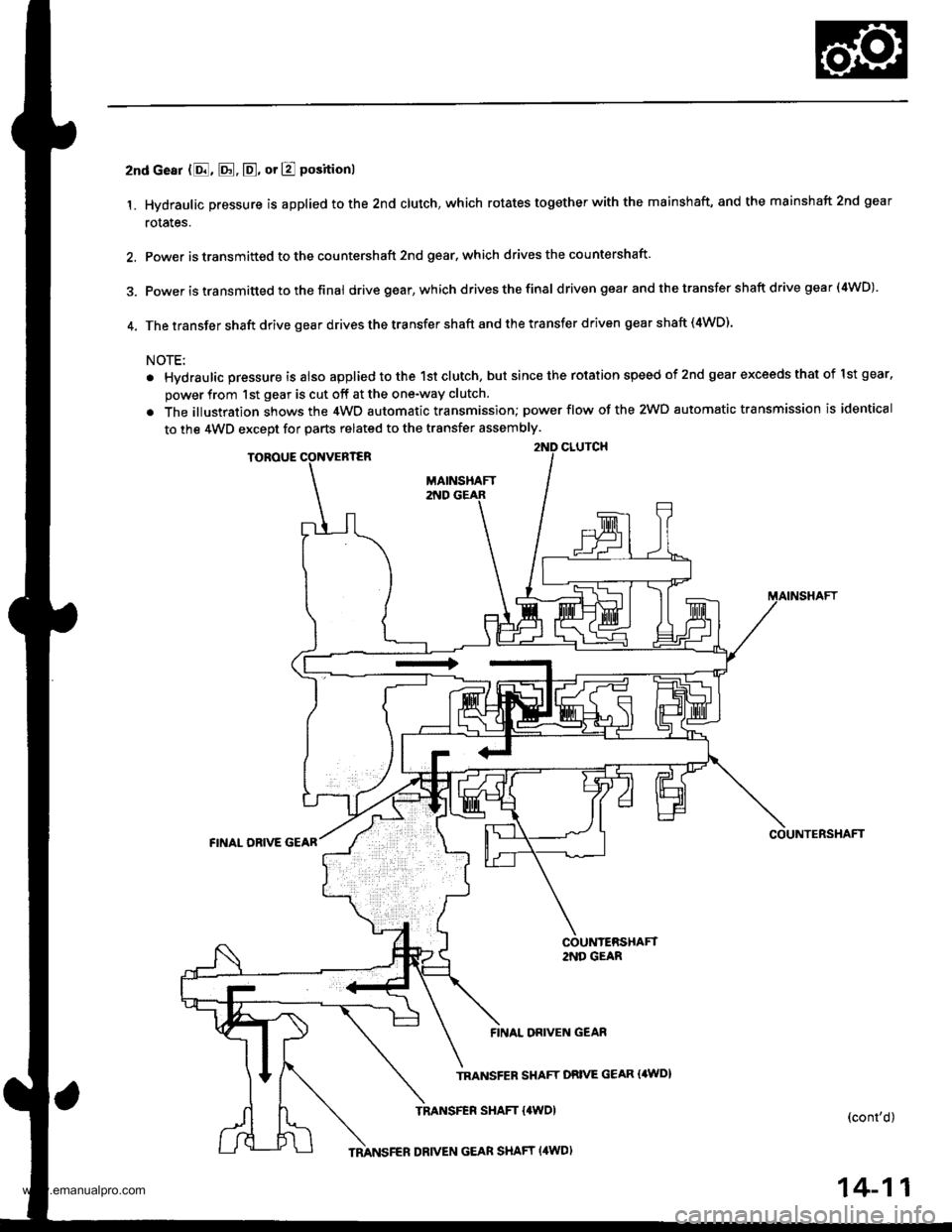
2nd cesr (8, E. E, or E positionl
1. Hydraulic pressure is applied to the 2nd clutch, which rotates together with the mainshaft, and the mainshaft 2nd gear
rotales.
2. Power is transmitted to the countershaft 2nd gear, which drives the countershaft
3. power is transmitted to the final drive gear, which drivesthefinal d riven gear and the transfer shaft drive gea r (4WD)
4. The transfer shaft drive gear drives the transfer shaft and the transfer driven gear shaft (4WD).
NOTE:
. Hvdraulic pressure is also applied to the 1st clutch, but since the rotation speed of 2nd gear exceeds that of lst gear.
power from 1st gear is cut off at the one-way clutch.
. The illustration shows the 4WD automatic transmission; power flow of the 2WD automatic transmission is identical
to the 4WD except for parts related to the transfer assembly.
CLUICHTOROUE
COUNTERSHAFTFINAL ORIVE GEAR
2NO GEAR
FINAL DRIVEN GEAF
TRANSFER SHAFT DBIVE GEAR {4WD}
TRANSFER SHAFT {4WDI(cont'd)
TMNSFER DRIVEN GEAR SHAFT (4WD)
14-11
www.emanualpro.com
Page 528 of 1395
Description
Power Flow (cont'd)
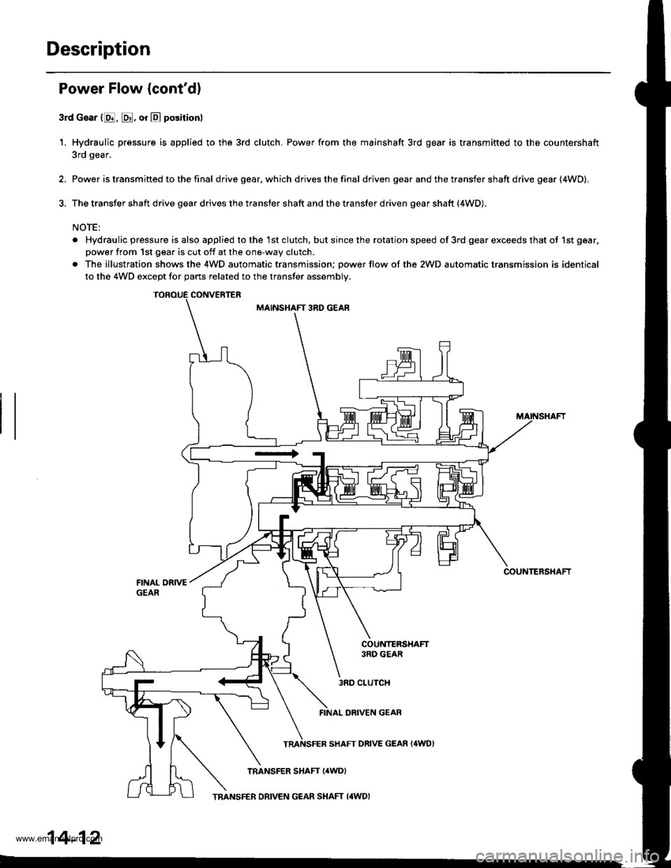
3rd Gear {8. @, or @ position)
1. Hydraulic pressure is applied to the 3rd clutch. Power from the mainshaft 3rd gear is transmitted to the countershaft
3rd gear.
2. Power is transm ifted to the final d rive gear, wh ich d rives the f inal driven gear and the transfer shaft drive gear (4WD).
3, The transfer shaft drive gear drives the transter shaft and the transfer driven gear shaft (4WD).
NOTE:
. Hydraulic pressure is also applied to the 1st clutch, but since the rotation speed of 3rd gear exceeds that of 1st gear,
power from lst gear is cut off at the one-way clutch.
. The illustration shows the 4WD automatic transmission; Dower flow of the 2WD automatic transmission is identical
to the 4WD except for parts related to the transfer assembly.
CONVERTEF
MAINSHAFT 3RD GEAR
COUNTERSHAFT
COUNTERSHAFT3RO GEAR
3RD CLUTCH
DRIVEN GEAR
SHAFT DRIVE GEAR (4WO)
TRANSFER SHAFT (,lwDl
TRANSFER ORIVEN GEAN SHAFT (4WD)
14-12
www.emanualpro.com
Page 529 of 1395
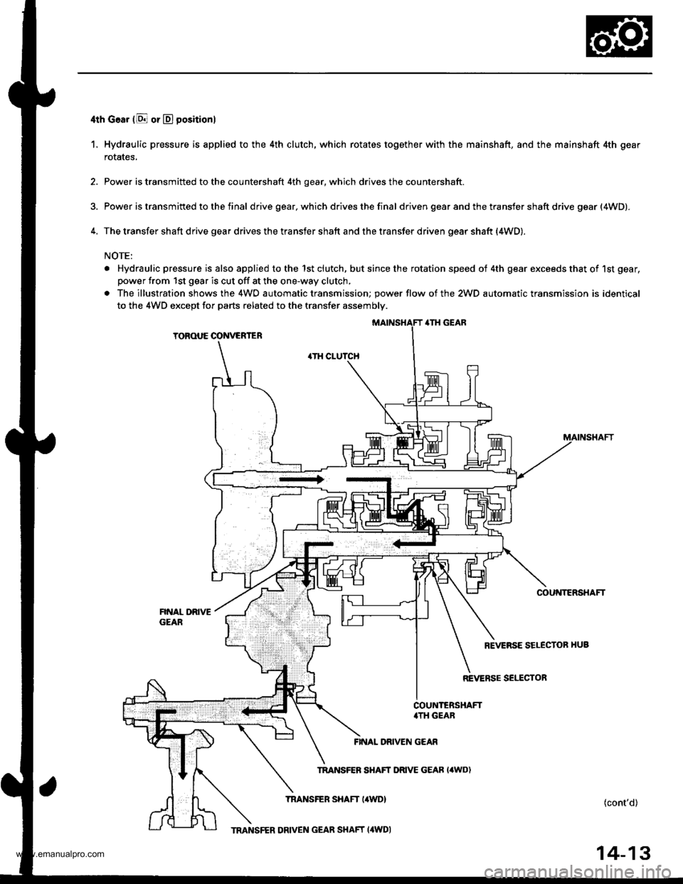
4th Goar (E or D positionl
1. Hydraulic pressure is applied to the 4th clutch, which rotates together with the mainshaft, and the mainshaft 4th gear
rotates,
2. Power is transmitted to the countershaft 4th gear, which drives the countershaft.
3. Power is transm ifted to the f inal d rive gear, which drives the fina I driven gear and the transfer shaft drive gear (4WD).
4. The transfer shaft drive gear drives the transfer shaft and the transfer driven gear shaft {4WD).
NOTE:
. Hydraulic pressure is also applied to the 1st clutch, but since the rotation speed of 4th gear exceeds that of 1st gear,
power from 1st gear is cut off at the one-way clutch,
. The illustration shows the 4WO automatic transmission; power flow of the 2WD automatic transmission is identical
to the 4WD except for parts related to the transfer assembly.
ilTH GEAR
TOROUE CONVERTER
.TH CLUTCH
COU'{TERSHAFT
REVERSE SELECTOR HUB
REVERSE SELECTOR
FINAL DRIVEN GEAR
TRANSFEB SHAFT DRIVE GEAB I'WD)
TNANSFER SHAFT I4WDI{cont'd)
14-13
TMNSFER DRIVEN GEAR SHAFT (4WDI
www.emanualpro.com
Page 530 of 1395
Description
Power Flow (cont'dl
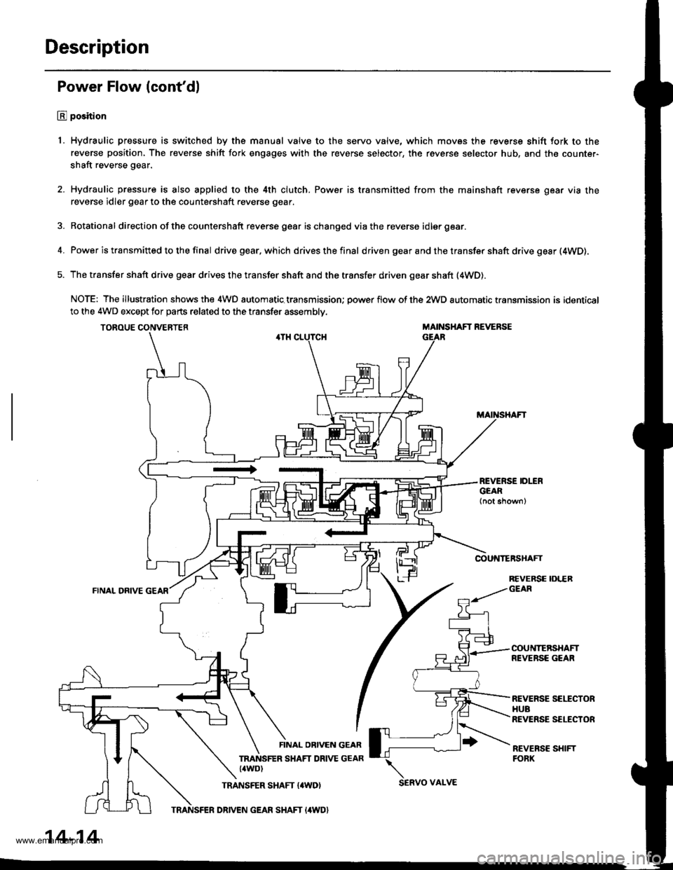
E position
1. Hydraulic pressure is switched by the manual valve to the servo valve, which movss the reverse shift fork to the
reverse position, The reverse shift fork engages with the reverse selector, the reverse selector hub, and the counter-
shaft reverse gear.
2. Hydraulic pressure is also applied to the 4th clutch. Power is transmitted from the mainshaft reverse gear via the
reverse idler gear to the countershaft reverse gear.
3. Rotational direction ofthe countershaft reverse gear ischanged viathe reverse idlergear.
4. Power is transmitted to the final drivegear,which drivesthefinal d riven gear a nd the transfer shaft drive gesr (4WD).
5. The transfer shaft drive gear drives the transfer shaft and the transfer driven gear shaft (4WD).
NOTE: The illustration shows the 4WD automatic.transmission; power flow of the 2wD automatic transmission is identical
to the 4WD except for parts related to the transfer assembly.
TOROUE CONVERTERMAINSHAFT REVERSE
COUNTERSHAFT
FINAL ORIVE
REVERSE IDLERGEAR
COUNTERSHAFTREVERSE GEAR
REVERSE SEITCTORHUBREVERSE SELECTOR
REVEBSC SHIFTFORK
FINAL OBIVEN GEAR
TRANSFER SHAFT DRIVE GEAR{4WD)
TRANSFER SHAFT {4WD)SERVO VAI-VE
14-14
TRANSFER DRIVEN GEAR SHAFT I4WD}
www.emanualpro.com
Page 535 of 1395
![HONDA CR-V 1997 RD1-RD3 / 1.G Owners Guide
Ascending Control {37 Modol}
When the PCM determines that the vehicle is climbing a hill in E] and E positions, the system extends the engagement
area of 2nd g€ar and 3rd gear to prevent the transm HONDA CR-V 1997 RD1-RD3 / 1.G Owners Guide
Ascending Control {37 Modol}
When the PCM determines that the vehicle is climbing a hill in E] and E positions, the system extends the engagement
area of 2nd g€ar and 3rd gear to prevent the transm](/img/13/5778/w960_5778-534.png)
Ascending Control {37 Modol}
When the PCM determines that the vehicle is climbing a hill in E] and E positions, the system extends the engagement
area of 2nd g€ar and 3rd gear to prevent the transmission from frequently shifting between 2nd and 3rd gears, and
between 3rd and 4th gears, so the vehicle can run smooth and have more power when needed.
NOTE:
. Shift schedules stored in ths PCM between 2nd and 3rd gears, and between 3rd and 4th gears. enable the PCM's fuzzy
logic to automatically select the most suitable gear according to the magnitude of 8 gradient.
t Fuzzy logic is a form of artificial intslligence that lets computers respond to changing conditions much like a human
mind would.
3RD - tlTHASCENoING MODE: UFhift Sch.dulc
- . FLAT ROAD MODE
-----------. : GRADUAL ASCENDING MODE
- - - - - : STEEPASCENDING MODEo5l)
FFN1NS
7,.,.7a
: 2ND-3RD SHIFTING CHARACTERISTICSCONTROL AREA| 3RD-aTH SHIFTING CHARACTER|SnCSCONTROL AREA
62 mph
1100 km/h)Vehicle .o..d
Asconding Conirol ('98 - 00 Mod.ls)
When the PCM determines that the vohicle is climbing a hill in E] and E positions ('98 model), and in E] position ('99 -
00 models), the system extends the engagement srea of 2nd gear and 3rd gear to prevent the transmission from frequent-
ly shifting between 2nd and 3rd gears, and between 3rd and 4th gears, so the vehicle can run smooth and have more
power when needed.
NOTE: Shift schedulss stored in the PCM between 2nd and 3rd gears, and between 3rd and 4th gears, enable to selsct the
most suitable gear according to th6 magnitude of a gradi€nt.
ASCENDING MODE: Up.hift Sch.dul.
NN : 2ND-3RD SXImNG CHARACTERISTICS- GoNTRoLAREA
VVVVVZ:IRD-ITHSHIFnNGCHARACTERISTICS- cot{TRoL AREA
850
o
6:l mph11fl) km/hl
(cont'd)
2ND - 3RD
2ND + 3RD 3RD + 4TH
Vahicl. sDctd
14-19
www.emanualpro.com
Page 546 of 1395
Description
Hydraulic Flow (cont'dl
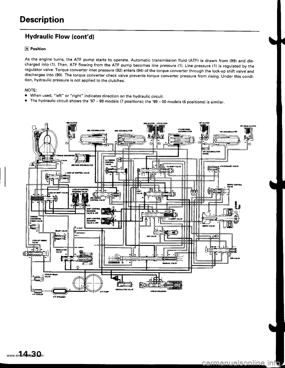
lll Position
As the engine turns, the ATF pump starts to operate. Automatic transmission fluid (ATF) is drawn from (99) and dis-charged into (1). Then, ATF flowing from the ATF pump becomes line pressure ('l). Line pressure (1) js regulated by theregulator valve. Torque converter inlet pressure {92) enters (94) of the torque conveTter through the lock-up shift valve anddischarges into (90) The torque converter check valve prevents torque converter pressure from rising. Under this condi-tion, hydraulic pressure is not applied to the clutches.
NOTE;
. When used. "|eft" o. "right" indicates direction on the hvdraulic circutt.. The hydraulic circuit shows the '97 - 98 models {7 positions}; the '99 - 00 models (6 positions) is similar.
'lF'.j.l
14-30
www.emanualpro.com
Page 577 of 1395
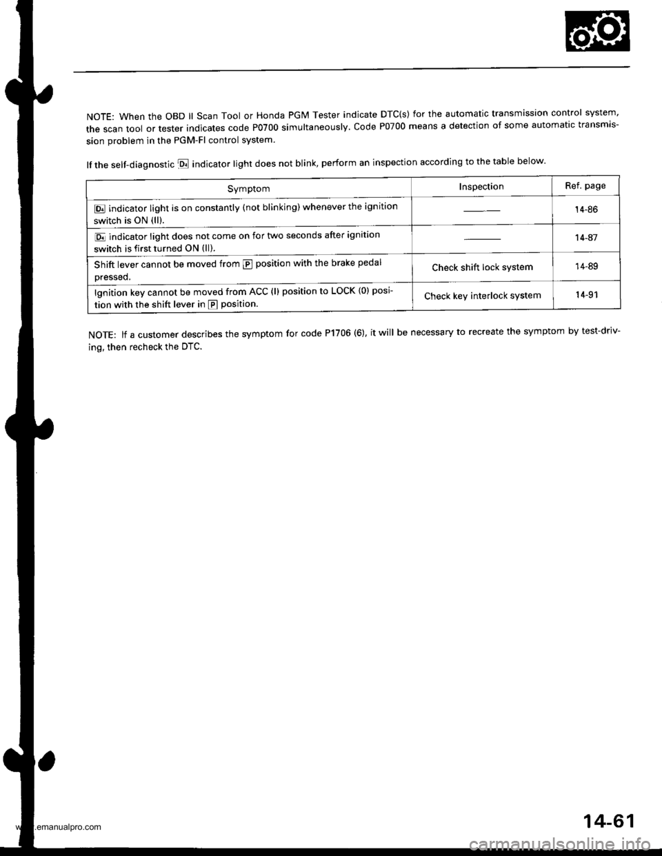
NOTE: When the OBD ll Scan Tool or Honda PGM Tester indicate DTC(s) for the automatic transmission control system'
the scan tool or tester indicates code P0700 simultaneously. code P07oo means a detection of some automatic transmis-
sion problem in the PGM-Fl control system
lf the self-diagnostic E indicator light does not blink, perform an inspection according to the table below.
NOTE: lf a customer describes the symptom for code P1706 (6), it will be necessary to recreate the symptom by test-driv-
ing, then recheck the OTC.
SymptomInspectionRef. page
E indicator light is on constantly (not blinking) whenever the ignition
switch is ON (ll).14-86
E indicator light does not come on for two seconds after ignition
switch is first turned ON (ll).
't 4-41
Shift lever cannot be moved from @ position with the brake pedal
Dressed,Check shift lock system14-89
lgnition key cannot be moved from ACC (l) position to LOCK {0) posi
tion with the shift lever in E position.Check keY interlock system14-91
14-61
www.emanualpro.com
Page 579 of 1395
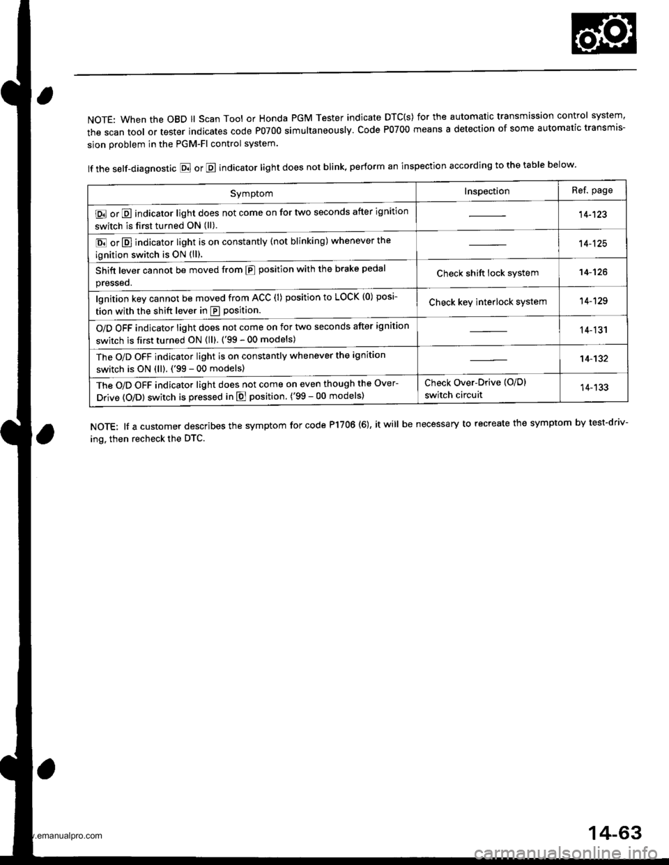
NOTE: When the OBD ll Scan Tool or Honda PGM Tester indicate DTC(S) for the automatic transmission control system,
the scan tool or tester indicates code P0700 simultaneously. Code P0700 means a detection of some automatic transmis-
sion problem in the PGM-Fl control system.
lf the self-diagnostic E or E indicator light does not blink, perform an inspection according to the table below.
NOTE: lf a customer describes the symptom for code P17OO (6), it will be necessary to recreate the symptom by test-driv-
ing. then recheck the DTC.
SymptomInspectionRef. page
E or E indicator light does not come on for two seconds after ignition
switch is first turned ON (ll).14-123
E or E] indicator light is on constantly (not blinking) whenever the
ignition switch is oN {ll).
14-125
Shift lever cannot be moved from E position with the brake pedal
presseo.Check shift lock system14-'t26
lgnition key cannot be moved from ACC (l) position to LOCK (0) posi-
tion with the shift lever in E position.Check key interlock system14-129
O/D OFF indicator light does not come on for two seconds after ignition
switch is first turned ON (ll). ('99 - 00 models)14-131
The O/D OFF indicator light is on constantly whenever the ignition
switch is ON (ll). ('99 - 00 models)14-132
The O/D OFF indicator light does not come on even though the Over-
Drive (O/Dl switch is pressed in E position. ('99 - 00 models)
Check Over-Drive {O/D}
switch circuit14-133
14-63
www.emanualpro.com
Page 676 of 1395
Fluid Level
Checking
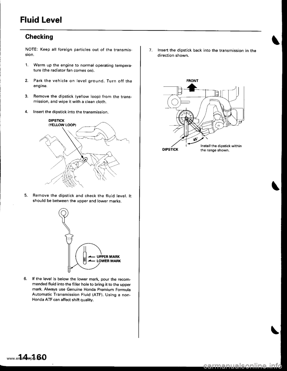
NOTE: Keep all foreign particles out of the transmis-
ston,
1. Warm up the engine to normal operating tempera-ture (the radiator fan comes on)
Park the vehicle on level ground. Turn off theengine.
Remove the dipstick (yellow loop) from the trans-mission, and wipe it with a clean cloth.
Insert the dipstick into the transmission.
DIPSTICK
Remove the dipstick and check the fluid level. lt
should be between the upper and lower marKs.
lf the level is below the lower mark. pour the recom-mended fluid into the filler hole to bring it to the uppermark, Always use Genuine Honda Premium FormulaAutomatic Transmission Fluid (ATF). Using a non-Honda ATF can affect shift oualitv.
lt
El--
UPPERMARKMARK
14-160
7. Insert the dipstick back into the transmission in the
direction shown.
DIPSTICK
FRONT
-'-Y'
Insrall the dipstick within
www.emanualpro.com
Page 677 of 1395

Pressure Testing
Changing
NOTE: Keep all foreign particles out of the transmis-
sion.
1. Bring the transmission up to operating temperature
(the radiator fan comes on) by driving the vehicle.
Park the vehicle on level ground. turn the engane
off. then remove the drain Plug.
NOTE: lf a cooler flusher is to be used, see page
14-264 and 14-265.
TRANSMISSIONEND COVER
DRAIN18 x 1.5 mmSEALING WASHEBReplace.49 N.m {5.0 kgt.m, 36 lbf.tl)
Reinstall the drain plug with a new sealing washer,
then refill the transmission with the recommended
fluid to the uDper mark on the dipstick. Always use
Genuine Honda Premium Formula Automatic
Transmission Fluid (ATF) Using a non-Honda ATF
can affect shift quality.
Automatic Transmission Fluid Capacity:
4WD;
2.9 { (3.1 US qt. 2.6 lmp qt) 8t change
5.8 ? {7.2 US $, 6.0 lmp qt} at ovethaul
2WD:
2.7 | l2.S US qt,2.1lmp qtl ai change
5.9 ? {6.2 US $, 5.2 lmp qtl at ovolhaul
2.
a
a
1.
Wlrile testing, be careful of the rotaling wheols.
Mako sure lifts, iacks, and safety stands ar€ placed
properly (see scction 11.
Before testing, be sure the transmission fluid is
filled to the proPer level.
4WD:
Raise the vehicle (see section 11.
2WD:
Raise the front of the vehicle, and make sure it is
securely supported. Set the parking brake, and block
both rear wheels securely.
Allow all four wheels {4WD) or front wheels (2wD}
to rotate freely.
Warm up the engine (the radiator fan comes on),
then stop it and connect the tachometer.
Connect the oil pressure gauges to each inspection
hole securely, and do not allow dust or other foreign
particles to enter the inspection holes.
TOROUE: 18 N'm ll.8 kgf'm, 13 lbf'ft)
5.
A/T PRESSURE HOS€,2210 mm07MAJ - PYiOllA
{4 Requircd}
,4'/"' ,a
W'
A/T PRESSURE HOSEADAPTER07MAJ - PYt0120(il Rcquiledl
6. Measure the following Pressure:. Line Pressure ..........,14-162
. 1st. 1st-hold Clutch Pressure .............'. 14-162
. 2nd,3rd and 4th Clutch Pressure .......... 14-163
7. Install new sealing washers and the sealing bolts in
the inspection holes, and tighten to the specified
toroue.
(cont'd)
A/T OIL PRESSUREGAUGE SET W/PANEL07{06 - 0020400
/4\\-J-- (
+..\.-.\-'-\
A/T LOW PBESSUREGAUGE w/PANEL07406 - 0070300
TOROUE: 18 N'm 11.8 kgf'm, 13 lbf'ft)
14-161
www.emanualpro.com