Automatic HONDA CR-V 1997 RD1-RD3 / 1.G Repair Manual
[x] Cancel search | Manufacturer: HONDA, Model Year: 1997, Model line: CR-V, Model: HONDA CR-V 1997 RD1-RD3 / 1.GPages: 1395, PDF Size: 35.62 MB
Page 853 of 1395
Troubleshooting
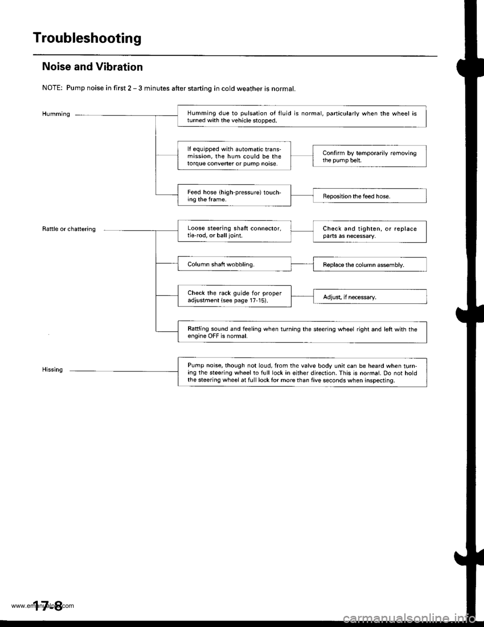
Noise and Vibration
NOTE: Pump noise in first 2 - 3 minutes after starting in cold weather is normal.
Humming
Rattle or chattering
Humming due to pulsation of fluid is normal, particularly when the wheel isturned with the vehicle stooDed.
lf equipped with automatic trans-mission, the hum could be thetorque converter or pump noase.
Confirm by temporarily removingthe pump belt.
Feed hose (high-pressure) touch-ing the frame.Beposition the feed hose.
Loose steering shaft connector,tie-rod, or balljoint.Check and tighten, or replaceparts as necessary,
Column shaft wobbling.Roplace the column assembly.
Check the rack guide for properadjustment (see page 17-15).Adjust, if necessary.
Rattling sound and feeling when turning the steering wheel right and left with th€engine OFF is normal.
Pump noise, though not loud, from the valve body unit can be heard when turn-ing the steering wheel to full lock in either direction. This is normal. Do not holdthe steering wheel at full lock lor more than five seconds when inspecting.
17-8
www.emanualpro.com
Page 860 of 1395
Rack Guide Adjustment
1.
6.
7.
5.
4.
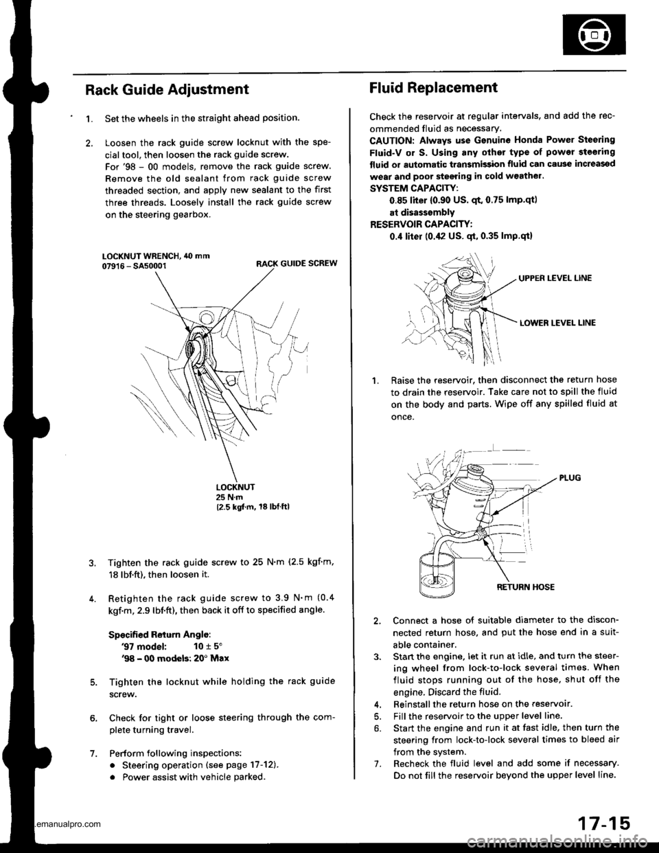
Set the wheels in the straight ahead position.
Loosen the rack guide screw locknut with the spe-
cialtool, then loosen the rack guide screw.
For'98 - 00 models, remove the rack guide screw.
Remove the old sealant from rack guide screw
threaded section, and apply new sealant to the first
three threads. Loosely install the rack guide screw
on the steering gearbox.
RACK GUIDE SCREW
LOCKNUT25 N.m
12.5 kgt m, 18lbtftl
Tighten the rack guide screw to 25 N.m (2.5 kgf'm,
18 lbf.ft), then loosen it.
Retighten the rack guide screw to 3.9 N'm (0.4
kgf.m, 2.9 lbf.ft), then back it off to specified angle.
Specified Return Anglo:
37 model: 10 r 5"'98 - 00 modeb: 20' Max
Tighten the locknut while holding the rack guide
screw.
Check for tight or loose steering through the com-
plete turning travel.
Perform following inspections:
. Steering operation (see page 17-12).
. Power assist with vehicle parked
Fluid Replacement
Check the reseryoir at regular intervals, and add the rec-
ommended fluid as necessary.
CAUTION: Always use Gsnuine Honda Power Steering
Fluid-V or S. Using any other type of power steering
tluid or automatic transmission fluid can cause increassd
wear and poor steering in cold w3athel.
SYSTEM CAPACITY:
0.85 liter {0.90 US. qt. 0.75 lmp.qtl
at disasssmbly
RESERVOIR CAPACITY:
0.,1 liter (0.42 US. gt, 0.35 lmp.qi)
UPPEN LEVEL LINE
LOWER LEVEL LINE
1.Raise the reservoir. then disconnect the return hose
to drain the reservoir. Take care not to spill the fluid
on the body and parts. Wipe off any spilled fluid at
once.
2, Connect a hose of suitable diameter to the discon-
nected return hose, and put the hose end in a suit-
able container.
3. Stan the engine. let it run at idle, and turn the steer-
ing wheel from lock-to-lock several times. When
fluid stops running out of the hose, shut off the
engine. Discard the fluid.
4. Beinstallthe return hose on the reservoar.
5. Fill the reservoir to the upper level line,
6. Start the engine and run it at fast idle. then turn the
steering from lock-to-lock several times to bleed air
from the system.
7. Recheck the fluid level and add some if necessary.
Do not fill the reservoir beyond the upper level line.
www.emanualpro.com
Page 952 of 1395
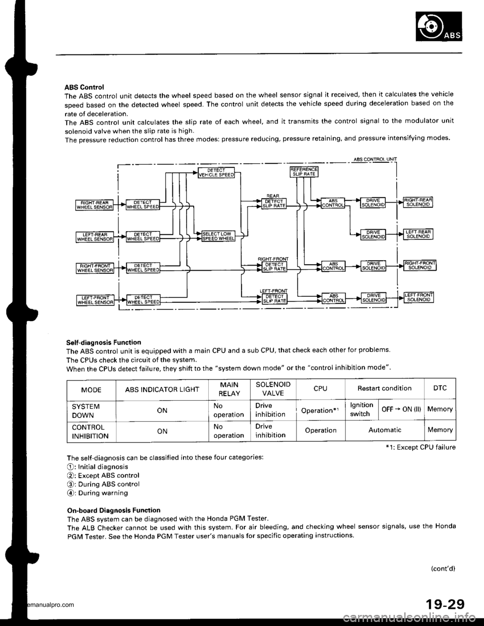
ABS Control
The ABS control unit detects the wheel speed based on the wheel sensor signal it received, then it calculates the vehicle
speed based on the detected wheel speed. The control unit detects the vehicle speed during deceleration based on the
rate of deceleration.
The ABS control unit calculates the slip rate of each wheel, and it transmits the control signal to the modulator unit
solenoid valve when the slip rate is high
The pressure reduction control has three modes: pressure reducing, pressure retaining, and pressure intensi{ying modes.
Self-diagnosis Function
The ABS control unit is equipped with a main cPU and a sub cPU, that check each other for problems.
The CPUs check the circuit of the system.
When the CPUS detect failure, they shift to the "system down mode" or the "control inhibition mode".
The self-diagnosis can be classitied into these four categories:
O: Initial diagnosis
O: Except ABS control
O; During ABS control
@: During warning
On-board Diagnosis Function
The ABS system can be diagnosed with the Honda PGM Tester.
The ALB Checker cannot be used with this system. For air bleeding. and checking wheel sensor signals, use the Honda
PGIM Tester. See the Honda PGM Tester user's manuals for specific operating instructions.
(cont'd)
19-29
ABS CONTROL I-INIT
MODEABSINDICATOR LIGHTMAIN
RE LAY
SOLENOID
VALVERestan conditionDTC
SYSTEM
DOWNONNo
operatron
Drive
inhibitionOperation*rlgnition
switchOFF - oN (ll)Memory
CONTROL
INHIBITIONONNo
operaton
Drive
inhibitionOperationAutomaticlVemory
*1: Except CPU failure
www.emanualpro.com
Page 959 of 1395
Troubleshooting Precautions
ABS lndicalor
1 lf the system is oK, the ABS indicator goes off two seconds after turning the ignition switch oN 1l) wathout staningthe engine, and then comes on again and goes off after two seconds. This occurs because the ABS control unit isturned on by the lG2 power source.2. The ABS indicator comes on when the ABS control unit detects a problem in the system. However, even thouoh thesystem is operating properly, the ABs indicator will come on too, under the following conditions:. Signal disturbance
. Wheel spin
. Only drive wheels rotate. Battery voltage fluctuates
To determine the actual cause of the problem, question the customer about the problem, taking these conditions intoconsideration:
3 When a problem is detected and the ABS indicator comes on, the indicator can stay on until the ignition switch isturned OFF, or it can automatically go off, depending on the mode.. Indicator stays on untilthe ignition switch is turned off: When the system is in the system down mode.. Indicator automatically goes off: When the system is in the control inhibition mode.4 The ABS indicator stays on when the system is reactivated without erasing the DTC, but it goes off after starting thevehicle.
When the wheel sensor system is faulty and the ABS indicator comes on. the algorithm of the system automatically turnsoff the ABS indicator after the wheel speed signal returns to the normal speed. Also, when the DTc is erased, the cpu isreset and the ABS indicator goes off when the system checked out normal by the initial diagnosis.Therefore, test-drive the vehicle after servicing the wheel sensor system. and be sure that the ABS indicator does notcome on.
5 When the ABS control unit outputs battery voltage to the gauge assembly, the ABS indicator ooes off.
Diagnostic Trouble Code (DTCI
1. The diagnostic trouble code (DTc) is memorized when a problem is detected and the ABS indicator does not go off,or when the ABS indicator comes on.The DTc is not memorized when the ABS indicator comes on unress the cpu is activated,2 The memory can hold any number of DTCs. However, when the same DTc is detected twice or more, the tater one iswritten over the old one.
Therefore, when the same problem is detected repeatedly, it is recorded as one DTC.3. The DTCs are indicated in the order of ascending number, not in the order they occur.4. The DTCS are memorized in the EEPROM (non-volatile memorv).Therefore, the memorized DTcs cannot be canceled by disconnecting the battery. perform the specified procedures toerase the DTCS.
Self-diagnosis
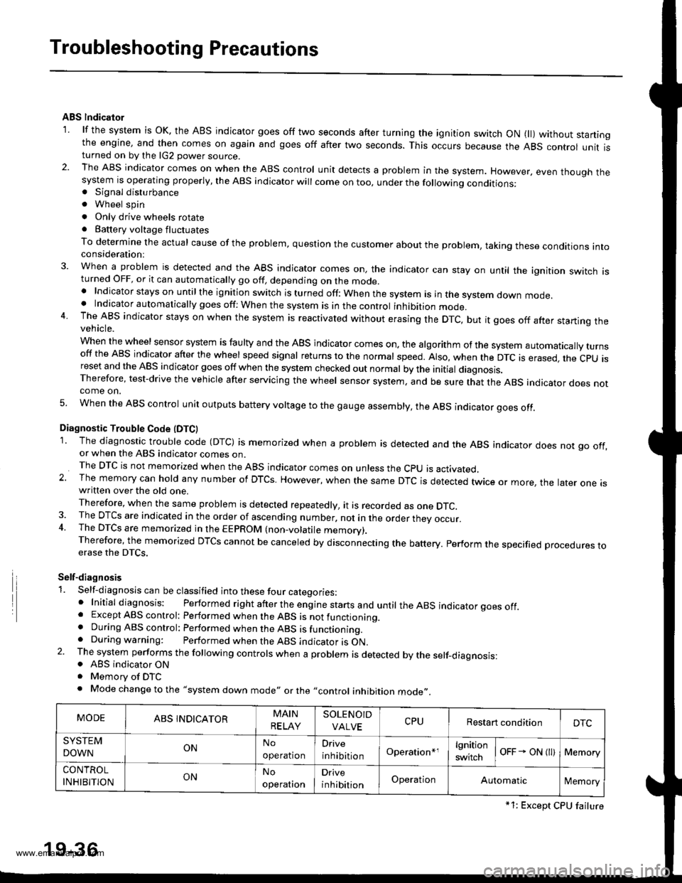
1. Self-diagnosis can be classified into these four categories:' Initial diagnosis: Performed right after the eng ine starts and untir theABS indicator goes off.. Except ABS control: Performed when the ABS is not functioning.. During ABS control: Performed when the ABS is functioning.. During warning: Performed when the ABS indicator is ON.2. The system performs the fo|owing contrors when a probrem is detected by the serf-diagnosis:. ABS indicator ON. Memorv of DTC. Mode changetothe "system down mode,, or the ,,control inhibition mode,,.
MODEABS INDICATORMAIN
RELAY
SOLENOID
VALVECPURestart conditionDTC
SYSTEM
DOWNONNo
operation
Drive
inhibitionOperation*rlgnition
switchoFF - ON l)Memory
CONTROL
INHIBITIONONNo
operal|on
Drive
inhibitionOperationAutomaticlMemory
*1: Except CPU failure
19-36
www.emanualpro.com
Page 1161 of 1395

Body Electrical
Speciaf Toofs ,...,..,.............-.23-2
Troubleshooting
Tips and Precautions ......,.,..........,.................. 23-3
Five-step Troubleshooting ........,.,.,...,,.,......... 23-5
Wire Color Codes ...,....,.. 23-5
Relay and Control Unit Locations
Engine Compartment ..,.,......,......................... 23-6
Dashboard ,.,.,..............-.- 23-7
Door ....................... .........23-10
Index to Cilcuits and Sysiems
Accessory Socket .. ,....,.,..,.,. 23-95*Airbags ................ .,....,. Sestion 24
Air Conditioning ,.,.,.... Section 22
Alternator ................... Section 4
Anti-lock Brake System {ABSI ................... Section 19'A/T Gear Position Indicator ....................... Section 1,1
Automatic Transmission System ...........,.. Section 14
Battery ................... ..............23-50
Blower Controls .,...,.,, Section 22
Charging System ....... Seqtion il
Clock -'98 Model ................ 23-98
Connector ldentification and Wire HarnessRouting .................. ......... 23.11
Cruise Control ............ Ssction 4
Dash Lights Brightness Contlo||er ..................... 23-90
Fan Conlrols ...,......,.... Section 10
Fuel Pump ,..,.,...,....,.... Section 11
Fuses...................... .,,.,.,.,.,,.,23-40*Gauges
Circuit Diagram ......-....-..23-58
Fuel Gauge .....,.,..... Section 11
Speedometer ..,..........,... 23-56
Ground Distribution ,....,.,...23-46
Hatch Glsss ODenor .........................,.,.,.,.,..,.,.,.,,. 23-121
Heater Controls .-........ Soction 21*Horns.,...,..,.,.,....... ................23"104*fgnition Switch ,,.,.,..,.,.,,.,.,.,23-51
lgnition Key Light System -'97 Mod6l .............. 23.88
-+
BODY
www.emanualpro.com
Page 1307 of 1395
Inspection
SRS components ale located in this area. Review the
SRS component locations, precautions, and procedures
in this section (24) before preforming repairs or service
('98 - 00 models).
!!!@ To avoid accidontal deployment and possi-
6i6-'rnpry. att"ays aisconnsct th€ seat beh tensioner con-
n€ctor belore removing tho retrastor {.98 - 00 modols, seo
page2+231.
Rgtlastor Insgection
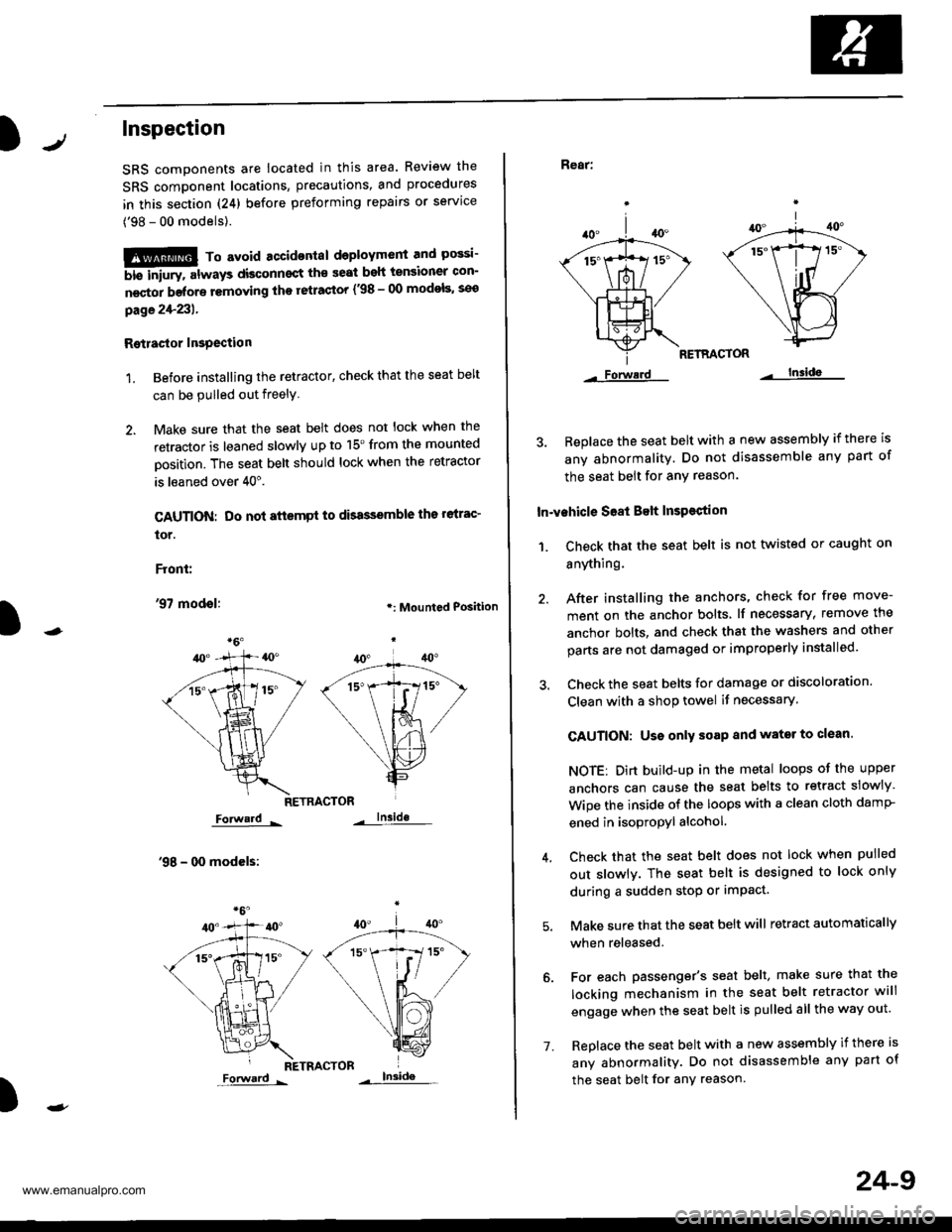
1. Before installing the retactor, check that the seat belt
can be pulled out freely
2. Make sure that the seat belt does not lock when the
retractor is leaned slowly up to 15'from the mounted
Dosition. The seat belt should lock when the retractor
is leaned over 40".
CAUTION: Do not attsmpt to dbassemble ths relrac'
tor.
Front:
'97 modol:.: Mounted Position
RETRACTOR
Forward -
'98 - 00 modcls:
lnside
RETRACTOR
)
Forward -
'1.
24-9
Rear:
RETRACTOR
Forwerd lnsida
3. Beplace the seat belt with a new assembly if there is
any abnormality. Do not disassemble any part of
the seat belt for any reason.
In-vehicle S68t Belt InsPestion
1. Ch€ck that the seat belt is not twisted or caught on
anything.
40.
/A
\|_t-.
*1ix
\/
Lls=
Forwerd
After installing the anchors, check for free move-
ment on the anchor bolts lf necessary, remove the
anchor bolts, and check that the washers and other
parts are not damaged or improperly installed.
Check the seat belts for damage or discoloration.
Clean with a shop towel if necessary.
CAUTION: Uso only soap and wator to clean.
NOTE: Dirt build-up in the metal loops of the upper
anchors can cause the seat belts to retract slowly
Wipe the inside of the loops with a clean cloth damP
ened in isopropyl alcohol.
Check that the seat belt does not lock when pulled
out slowlv. The seat belt is designed to lock only
during a sudden stop or impact.
Make sure that the seat belt will retract automatically
when released.
For each passenger's seat belt, make sure that the
locking mechanism in the seat belt retractor will
engage when the seat belt is pulled all the way out.
Replace the seat belt with a new assembly if there is
any abnormality. Do not disassemble any part of
the seat belt for any reason.
www.emanualpro.com
Page 1318 of 1395
JWiring Precautions
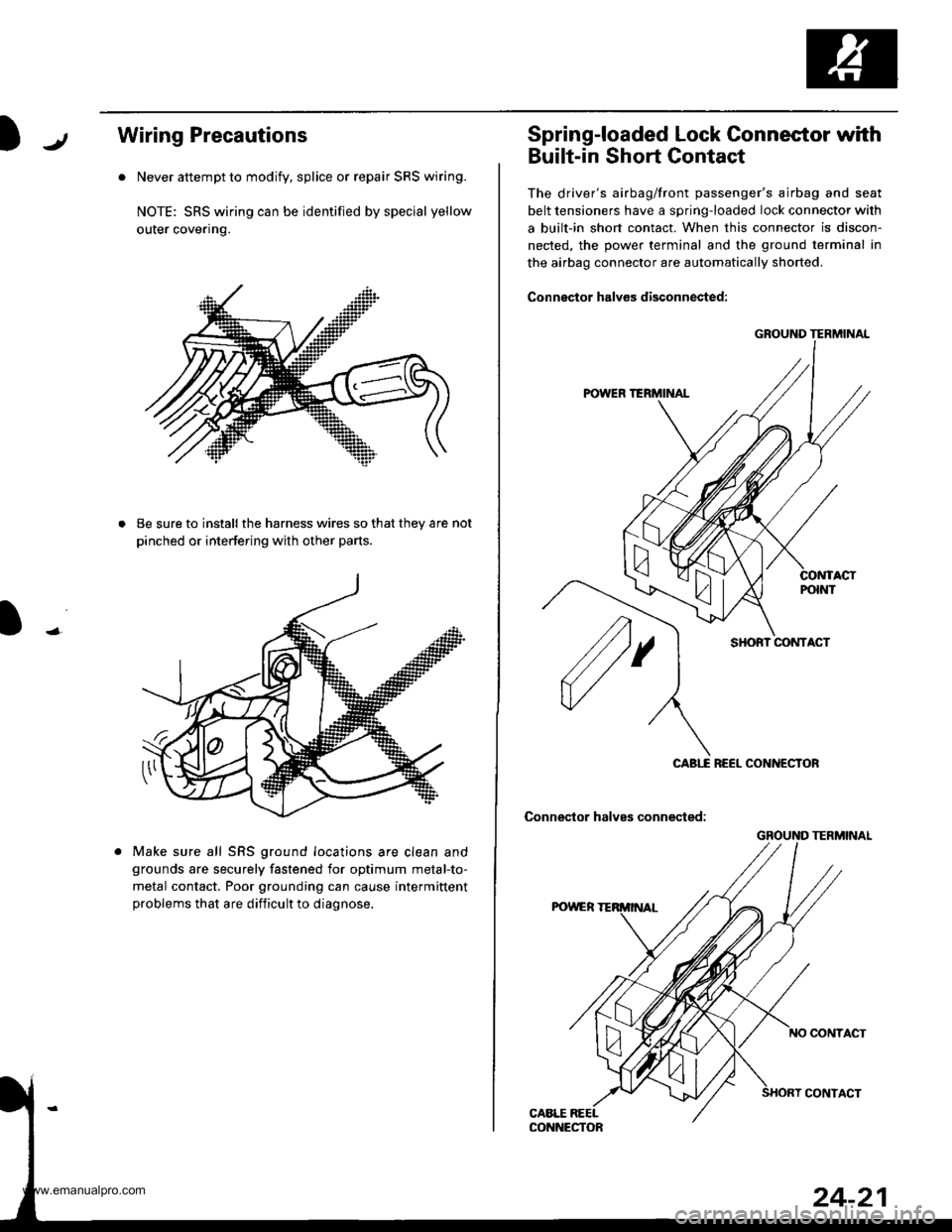
. Never attempt to modify, splice or repair SRS wiring.
NOTE: SRS wiring can be identified by special yellow
outer coveflng.
Be sure to install the harness wires so that they are
pinched or interfering with other parts.
Make sure all SRS ground locations are clean and
grounds are securely fastened for optimum metal-to-
metal contact. Poor grounding can cause intermittent
problems that are difficult to diagnose.
GROUND TERMINAL
CONTACT
CONTACT
24-21
Spring-loaded Lock Connestor with
Built-in Short Gontact
The driver's airbag/front passenger's airbag and seat
belt tensioners have a spring-loaded lock connector with
a built-in short contact. When this connector is discon-
nected, the power terminal and the ground terminal in
the airbag connector are automatically shorted.
Conngctor halvcs diSconnested:
GROUND TERMINAL
SHORT CONTACT
CABIf REEL CONNECTOR
Connector halves connected;
ACT
www.emanualpro.com
Page 1321 of 1395
Precautions/Procedures
Disconneeting the Airbag Connectors and the Seat Belt Tensioner
Connectors (cont'd)
1.Disconnect the battery negative cable, then discon-
nect the positive cable from the battery. and wait at
least three minutes.
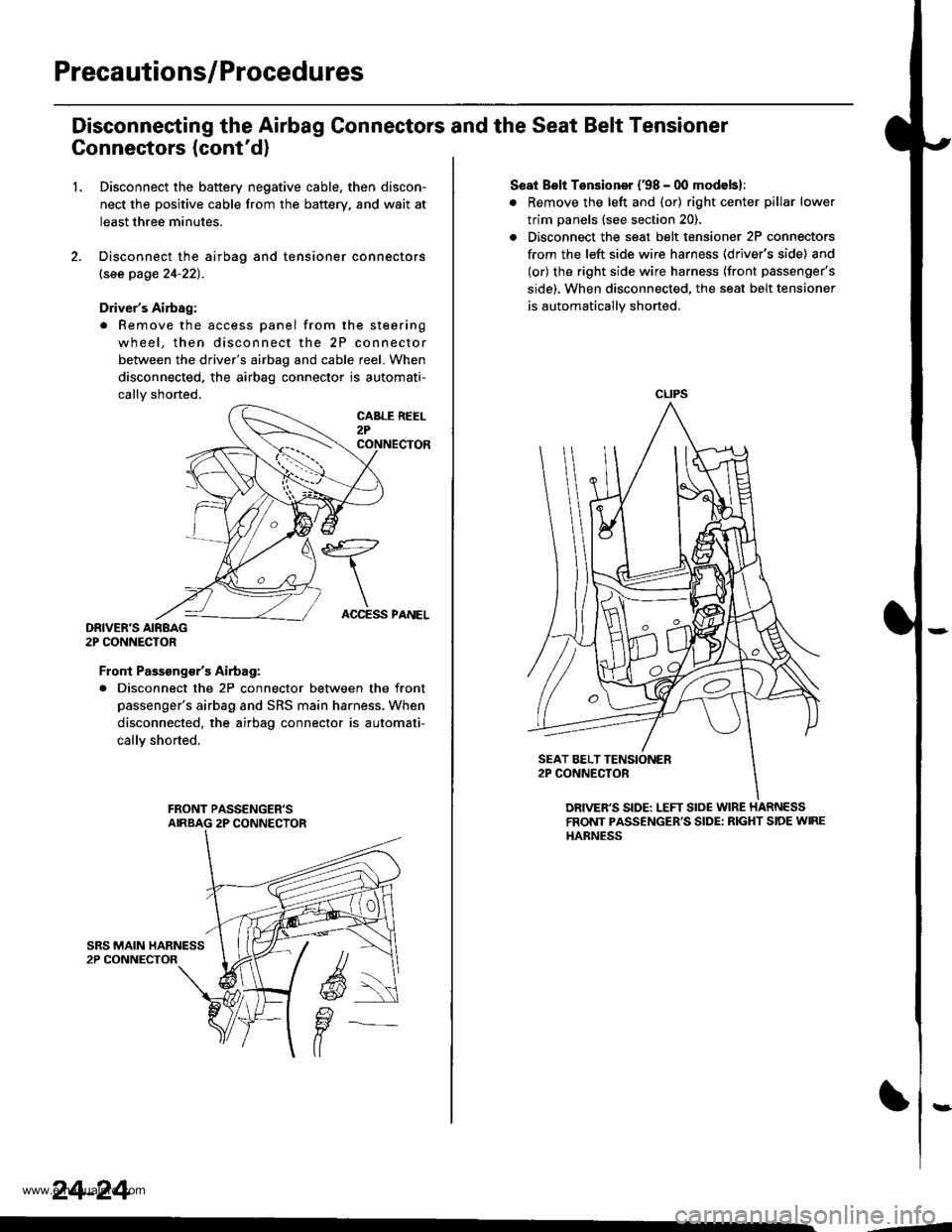
Disconnect the airbag and tensioner connectors
lsee page 24-22).
Driver's Airbag:
. Remove the access panel from the steering
wheel, then disconnect the 2P connector
between the driver's airbag and cable reel. When
disconnected, the airbag connector is automati-
callv shorted.
DRIVER'S AIRBAG2P CONNECTOR
Front Passsng€/sAirtag:
. Disconnect the 2P connector between the front
passenger's airbag and SRS main harness. When
disconnected. the airbag connector is automati-
callY shorted.
24-24
ACCESS PANEL
Seat Bslt Tensioner (38 - 00 modebl:
. Remove the left and (or) right center pillar lower
trim panels (see section 20).
. Disconnect the seat belt tensioner 2P connectors
from the left side wire harness (driver's side) and
(or) the right side wire harness (front passenger's
side). When disconnected. the seat belt tensioner
is automatically shorted.
CLIPS
DRIVER'S SIDE: LEFT SloE WIRE HARNESSFRONT PASSENGER'S SIDE: RIGHT SIDE WIREHARNESS
,--4
www.emanualpro.com
Page 1384 of 1395
Driver's Airbag
1.
Replacement
After a collision in which the airbags were deployed, the
airbags, the seat belt tensioners (if so equipped), and
the SRS unit must be replaced.
@ Store a removed airbag with the pad su.-
tacs up, lf th€ airbag is improperly stored face down.
accidental deployment could propal the unit with
enough forc€ io causg serioug iniury.
CAUTION:
. Always disconnoct the drivor's airbag connector
when the SRS main harness is disconnactod.
. Do not disassemble or tamper with ihe airbag.
NOTE:
Do not install used SRS parts from another vehicle,
When repairing, use only new SRS parts.
Carefully inspect the airbag before you install it. Do
not install an airbag that shows signs of being
dropped or improperly handled, such as dents, cracks
or deformation.
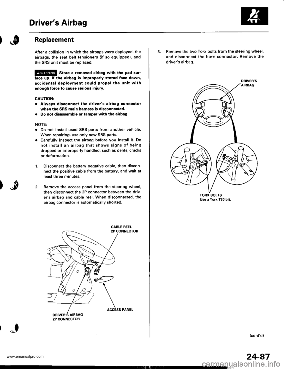
Disconnect the battery negative cable, then discon-
nect the positive cable from the battery, and wait at
least three minutes.
Remove the access panel from the steering wheel.
then disconnect the 2P connector between the driv-
er'6 airbag and cable reel. When disconnected. the
airbag connector is automatically shorted.
2P CONNECTON
ACCESS PANEL
24-87
3. Remove the two Torx bolts from the steering whsel,
and disconnect the horn connector. Remove the
driver's airbag,
(cont'd)
DRIVER'S
www.emanualpro.com
Page 1386 of 1395
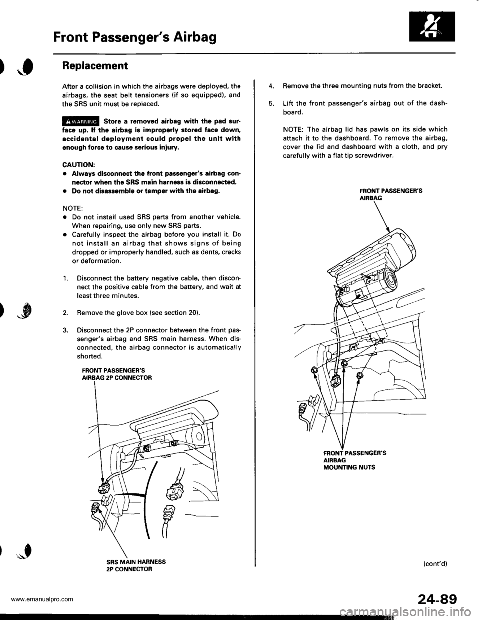
Front Passenger's Airbag
Replacement
After a collision in which the airbags were deployed, the
airbags, the seat belt tensioners (if so equipped), and
the SRS unit must be reolaced.
@ store a rsmovod airbag with lhe pad sur-
face up, It the airbag is improporly stor6d face down,
accidental doploym€nl could propsl ths unit withgnough forco to cause serious iniury.
CAUTION:
. Always disconnsqt the front pa3s6ng6r'3 airbag con-
noctor when tho SRS main harness is disconnocted,
. Do not disassambl6 or tamper with tho airbag,
NOTE:
. Do not install us6d SRS parts from another vehicle.
When repairing, use only new SRS parts.
. Carefully inspect the airbag before you install it. Do
not install an airbag that shows signs of being
dropped or improperly handled, such as dents, cracks
or deformation.
Disconnect the battery negative cable, then discon-
nect the positive cable from the battery. and wait at
least three minutes.
Remove the glove box (see section 20).
Disconnect the 2P connector between the front Das-
senger's airbag and SRS main harness, When dis-
connected, the airbag connector is automatically
shorted.
FRONT PASSENGER'S
1.
5.
Remove the three mounting nuts from the bracket.
Lift the front passsnger's airbag out of the dash-
DOaro.
NOTE: The airbag lid has pawls on its side which
attach it to the dashboard. To remove the airbag,
cover the lid and dashboard with a cloth, and pry
carefullv with a flat tip screwdriver.
FRONT PASSENGER'S
FRONT PASSENGER'SAIRBAGMOUNNNG NUTS
(cont'd)
24-49
www.emanualpro.com