Automatic HONDA CR-V 1997 RD1-RD3 / 1.G Service Manual
[x] Cancel search | Manufacturer: HONDA, Model Year: 1997, Model line: CR-V, Model: HONDA CR-V 1997 RD1-RD3 / 1.GPages: 1395, PDF Size: 35.62 MB
Page 681 of 1395
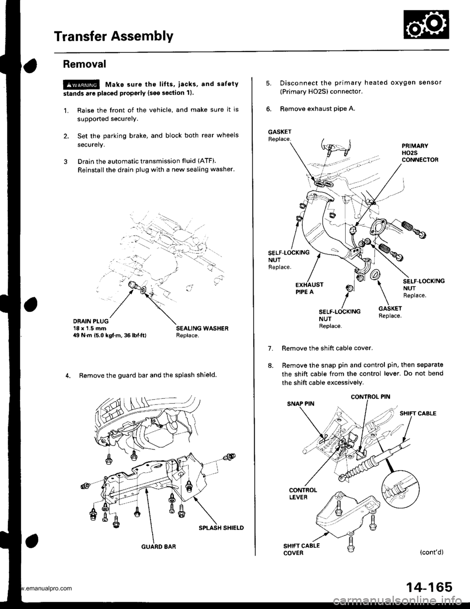
Transfer Assembly
Removal
@ Make sure the lifts, iacks, and safety
stands are placed properly (see section 11.
1. Raise the front of the vehicle, and make sure it is
supported securely.
2. Set the parking brake, and block both rear wheels
securelv.
3 Drain the automatic transmission fluid (ATF).
Reinstall the drain plug with a new sealing washer'
DRAIN PLUG'18 x'1.5 rnm49 N.m 15.0 kgf.m, 36 lbl.ftl
4. Remove the guard bar and the splash shield.
GUARD 8AR
14-165
5.Disconnect the primary heated oxygen sensor
{Primary HO2S) connector.
Remove exhaust pipe A.
SELF-LOCKINGNUTBeplace.
7.
SEI-F.LOCKINGNUTReplace.
NUTReplace
Remove the shift cable cover.
Remove the snap pin and control pin, then separate
the shift cable from the control lever. Do not bend
the shift cable excessively.
(cont'd)
www.emanualpro.com
Page 686 of 1395
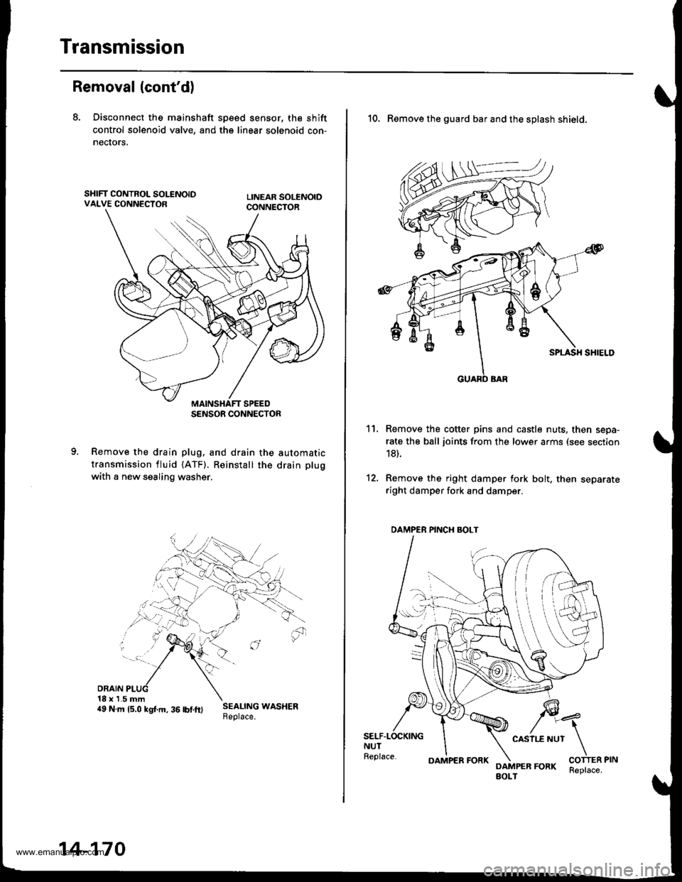
Transmission
Removal (cont'd)
8. Disconnect the mainshaft sp€ed sensor, the shift
control solenoid valve, and the linear solenoid con-
necrors,
Remove the drain plug. and drain the automatic
transmission fluid {ATF). Reinstall the drain plug
with a new sealing washer.
DRAIN18 x 1.5 mm4e N.m rs.o ksr.m. 36 rbrft) ;:i:$: *o"*."
SENSOR CONNECTOR
14-170
OAMPER FORKReplace.
10. Remove the guard bar and the splash shield.
Remove the cotter pins and castle nuts, then sepa-
rate the ball joints from the lower arms (see section
18).
Remove the right damper fork bolt, then separateright damper fork and damper.
11.
12.
SELF.LOCKINGNUTReplace.
CASII.E NUT
DAMPER FORKBOLT
DAMPER PINCH BOLT
www.emanualpro.com
Page 702 of 1395
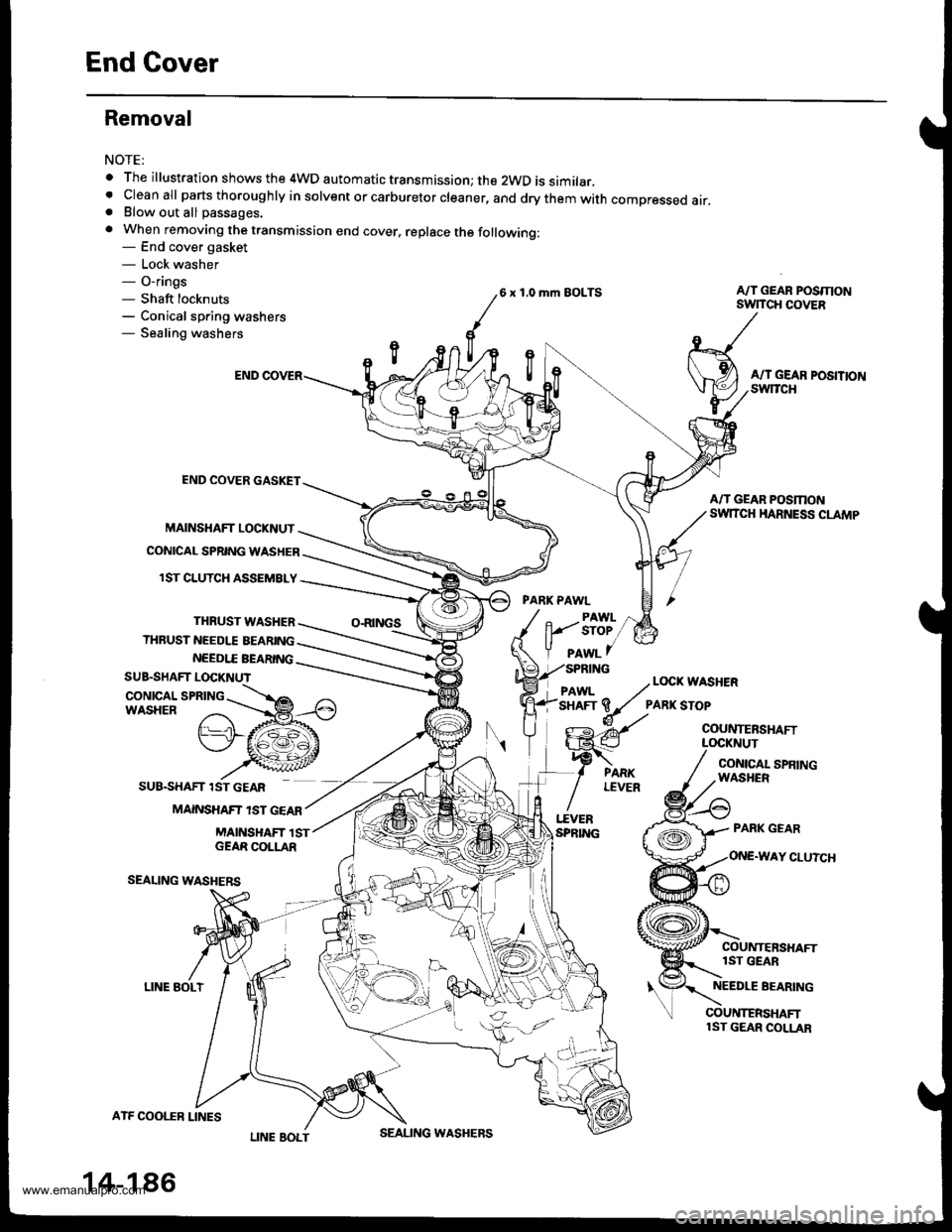
End Cover
Removal
NOTE:
o The illustration shows the 4WD automatic transmission; the 2WD is similar.. cleanall parts thoroughly in solvent or carburetor cleaner, and drythem with compressed air.. Blow out all passages.
. When removing the transmission end cover, replace the following:- End cover gasket- Lock washer- O-rings- Shaft locknuts- Conical spring washers- Sealing washers
END COVER GASKET
MAINSHAFT LOCKNUT
CONICAL SPRING WASHER
6 x 1 .0 rhm EOLTS
PARK PAWL
A/T GEAR POSMONSwlTCH COVER
NEEDI.T BEARING
SUB.SHAFT LOCKNUT
CONICAL SPRINGWASHER
LINE AOLT
ATF COOI.f B LINES
14-186
PAwL 7// Locx wASHER
'sHAFr 9/ ?ARK srop
o-- Ay' couNTERsHAFr
G-€ LocKNUr!€ / ..t,"o, "oo
A/T GEAR POSMONSW|TCH HARNESS CLAMP
CONICAL SPRINGWASHCR
A/T GEAR POSITION
PARK GEAR
Y CLUTCH
lST GEAR
NEEDLE BEARING
1ST CLUTCH ASSEMBLY
THRUST WASHER
THRUST NEEDLE AEARING
O.RINGS
\\
SUB.SHAFT 1ST GEAR
MAINSHAF? 'ST GEAR
MAINSHAFT 1STGEAR COLLAR
SEALING WASHERS
!€'-l
I"EVERSPRING
COUNTERSHAFTlST GEAR COLLAR
PAWL
lt1/ sroe
Y plwl f
L/'SPRING
LOCKNUT
LINE BOLTSEALING WASHERS
www.emanualpro.com
Page 704 of 1395
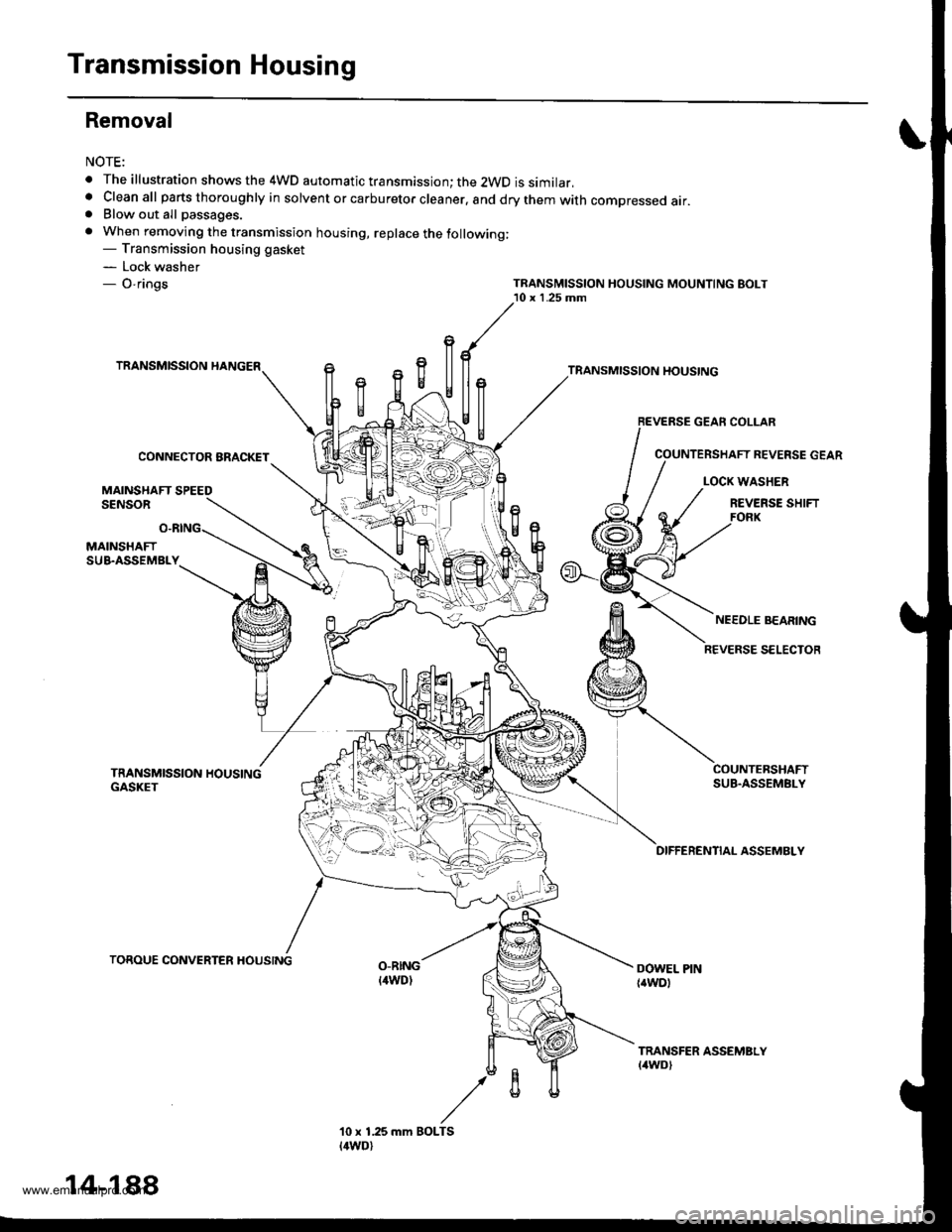
Transmission Housing
Removal
NOTE:
. The illustration shows the 4WD automatic transmission; the 2WD is similar,. Cleanall parts thoroughly in solvent or carburetor cleaner. and drythemwith compressed air.. Blow out all passages.
. When removing the transmission housing, replace the lollowing:- Transmission housing gasket- Lock washer- O-rings
TRANSMISSION HANGERTRANSMISSION HOUSING
REVERSE GEAN COLLAR
TRANSMISSION HOUSING MOUNTING EOLT
CONNECTOR BRACKET
MAINSHAFT SPEEDSENSOR
REVERSE GEAR
LOCK WASHER
REVERSE SHIFT
MAINSHAFTSUB.ASSEMBLY
TRANSMISSION HOUSINGGASKET
DIFFERENTIAL ASSEMBLY
TOROUE CONVERTER HOUSINGO-RINGt4wDl
TRANSFER ASSEMBLYt4wDt
10 x 1.25 mm
l4wo)
14-1 88
BOLTS
www.emanualpro.com
Page 706 of 1395
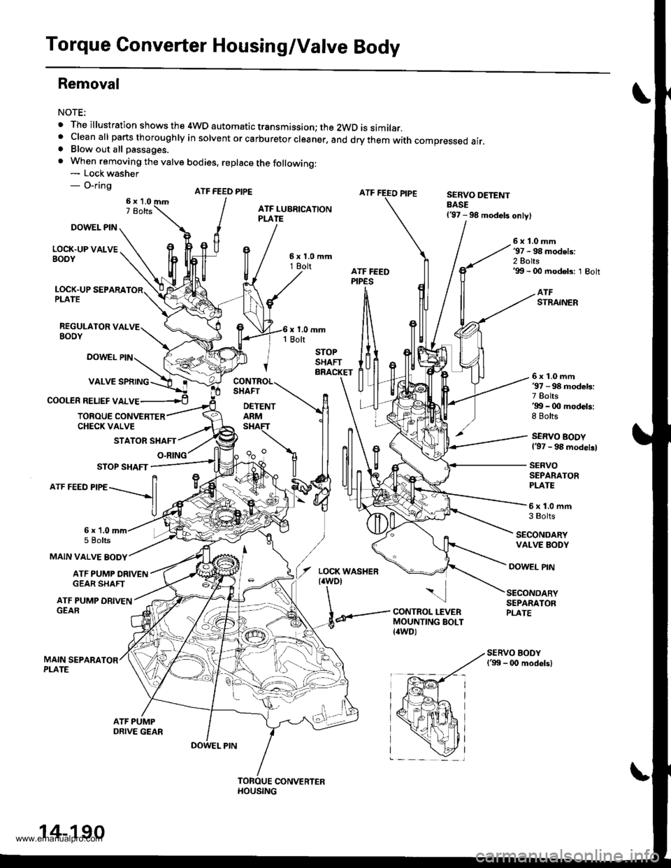
Torque Converter Housing/Valve Body
Removal
NOTE:
. The illustration shows the 4WD automatic transmission; the 2WD is similar.' cleanall parts thoroughry in sorvent or carburetor creaner, and drythem with compressed air.. Blow out all passages.
. When removing the valve bodies, replace the following:- Lock washer- O-ringATF FEED PIPESERVO DETENTBASE137 - 98 models only)
DOWEL PIN
LOCK.UP VALVEBOOY
6x1.0mm'97 - 98 models:2 Bolts'99 - 00 modeb: 1 Bolt
LOCK.UP SEPARAPLATE
REGULAIOR VALVEBOOY
ATFSTRAINER
DOWEL PIN
COOLER RELIEF VALVE
6x1.0mm37 - 98 models:7 Bolts'gg - 0O models:8 Bolts
SERVO BODY137 - 98 modelsl
SERVOSEPARATORPLATE
TOROUE CONVERTERCHECK VALVE
STATOR SHAFT
O.RING
5x1.0mfi3 Bolts
SECONDARYVALVE BODY
MAIN VALVE BODY
6x 1.05 Bolts
ATF PUMP ORIVENGEAR SHAFT
DOWEL PIN
ATF PUMP DRIVENGEAR
\
CONTROL LEVERMOUNTING BOLT{awD)
SECONDARYSEPARATORPLATE
14-190
www.emanualpro.com
Page 740 of 1395
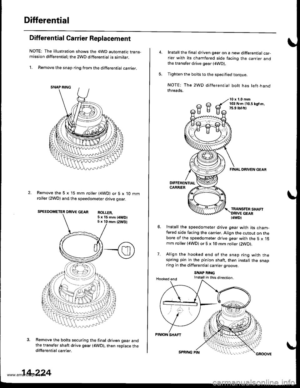
Differential
Differential Carrier Replacement
NOTE: The illustration shows the 4WD automatic trans-mission differential; the 2WD differential is similar.
1. Remove the snap ring from the differential carrier.
Remove the 5 x 15 mm roller (4WD) or 5 x 10 mmroller (2WDl and the speedometer drive gear.
SPEEDOMETER DRIVE GEAR RoI I FP
Remove the bolts securing the final driven gear andthe transfer shaft drive gear (4WD), then replace thedifferential carrier.
5 x 15 mm (/tWD)5 x 10 mm {2WDl
14-224
SPRING PINGROOVE
Install the final driven gear on a new differential car-rier with its chamfered side facing the carrier andthe transfer drive gear (4WD),
Tighten the bolts to the specified torque.
NOTE: The 2WD differentiat bolt has left-handthreads,
10 x 1.0 mm103 N.m 110.5 kd.m,7s.9 rbr.ft)
7.
FINAL DRIVEN GEAR
TRANSFER SHAFT
Install the speedometer drive gear with its cham-fered side facing the carrier. Align the cutout on thebore of the speedometer drive gear with the 5 x 15mm roller (4WD) or 5 x 10 mm roller (2WD).
Align the hooked end of the snap ring with thespring pin in the pinion shaft. then install the snaoring in the differential carrier groove
SNAP RINGInstall in this direction.Hooked end
PINION SHAFT
{4WDl
www.emanualpro.com
Page 766 of 1395
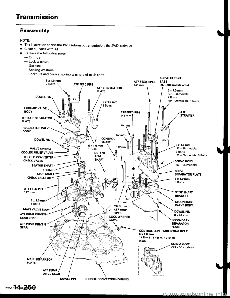
Transmission
Reassembly
NOTE:
. The illustration shows the 4WD automatic transmission; the 2WD is similar.. Clean all parts with ATF.. Replace the following parts:- O-rings- Lock washers- Gaskets- Sealing washers- Locknuts and conical spring washers of each shaft
ATF FEED PIPE
/
ATF FEED PIPES145 mm
SERVO DETENTBASE(37 -98 modeb onlylATF LUBRICATIONPLATE6x1.0mm
2 Bolts'99 - 00 models: 1 Bolts
LOCK.UP VALVEBODY
LOCK.UP SEPARATORPLATE
REGULATOR VALVEBODY
DOWEL PIN
DOWEL PIN
VALVE SPRING
STATOR SHAFT
'-
'112mmll,
rlT
ATFSTRAINER
40 mm
j coNrRoLI SHAFT
COOLER BELIEF VALVE
TOROUE CONVERTERCHECK VALVE
6x1.0mm18olts
DETENTARMSHAFT
6x1,0mm'97 - 98 models:7 Bolts'99 - 00 models:8 Bolts
SERVO BODY('97 - 98 models)
SERVOSEPARATOR PLATE
6x1.0mm3 Bolts
STOP SHAFTBRACKET
SECONDARYVALVE BODY
OOWEL PIN8x40mm
O.RING
STOP SHAFTCHECK BALLS 18'
ATF FEED PIPE112 mm
6x1.0mm5 Eolts
ATF PUMP DRIVENGEAR SHAFT
ATF PUMP DRIVEN
MAIN SEPARATORPLATE
MAIN VALVE EOOY
SECONDARYSEPARATOR
d---.- PLATE--.- CONTROL I.EVER MOUNTING BOLT6x1.0ftm14 N.m (1.4 kgt.m, 10 tbf.ft)(4WD)SERVO BODY('99 - 00 models)
ATF PUMP
6x1.0mm
ATF FEEO PIPE
) / 105.8
/,,!.,::(./ afF FEEO,/ ptpEs
EP,---!ir{+*a r
fpffi4 i
x*hi
_ \zl
14-250
DRIVE GEAR
DOWEL PINTOBOUEHOUSING
www.emanualpro.com
Page 769 of 1395
17.
18.
19.
20.
21.
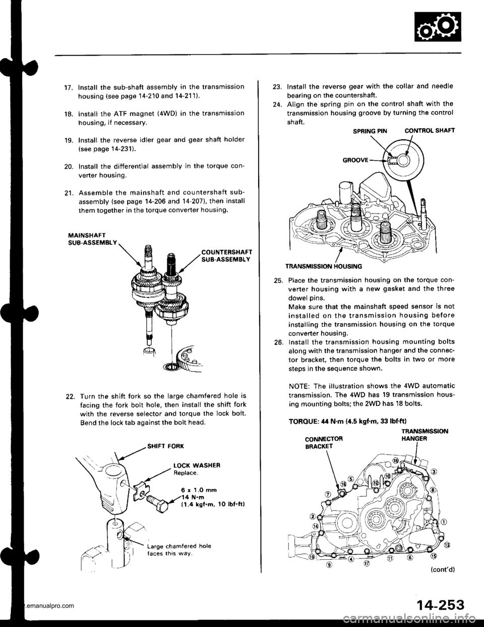
Install the sub-shaft assembly in the transmission
housing (see page 14-210 and 14-2'111.
lnstall the ATF magnet (4WD) in the transmission
housing, if necessary.
Install the reverse idler gear and gear shaft holder
(see page 14-231).
Install the differential assembly in the torque con-
verter housing.
Assemble the mainshaft and countershaft sub-
assembly (see page 14-206 and 14 207],, then install
them together in the torque converter houslng.
COUNTERSHAFTSUB-ASSEMBLY
Turn the shift fork so the large chamfered hole is
facing the fork bolt hole. then install the shift fork
with the reverse selector and torque the lock bolt.
Bend the lock tab against the bolt head.
SHIFI FORK
LOCK WASHERBeplace.
6 r 'l.O mm4 N.m(1.4 ksl.m. 1O lbt.ft)
Large chamfered hole
24.
Install the reverse gear with the collar and needle
bearing on the countershatt.
Align the spring pin on the control shaft with the
transmission housing groove by turning the control
shaft.
SPRING PIN CONTROL SHAFT
TRANSMISSION HOUSING
25. Place the transmission housing on the torque con-
verter housing with a new gasket and the three
dowel pins,
Make sure that the mainshaft speed sensor is not
installed on the transmission housing before
installing the transmission housing on the torque
converter housing.
26. Install the transmission housing mounting bolts
along with the transmission hanger and the connec-
tor bracket, then torque the bolts in two or more
steos in the seouence shown.
NOTE: The illustration shows the 4WD automatic
transmission. The 4WD has 19 transmission hous-
ing mounting bolts; the 2WD has 18 bolts.
TOROUE: 44 N.m {,[.5 kgf.m, 33 lbf'ft)
{cont'd)
14-253
SPRING PIN
TNANSMISSION
www.emanualpro.com
Page 800 of 1395
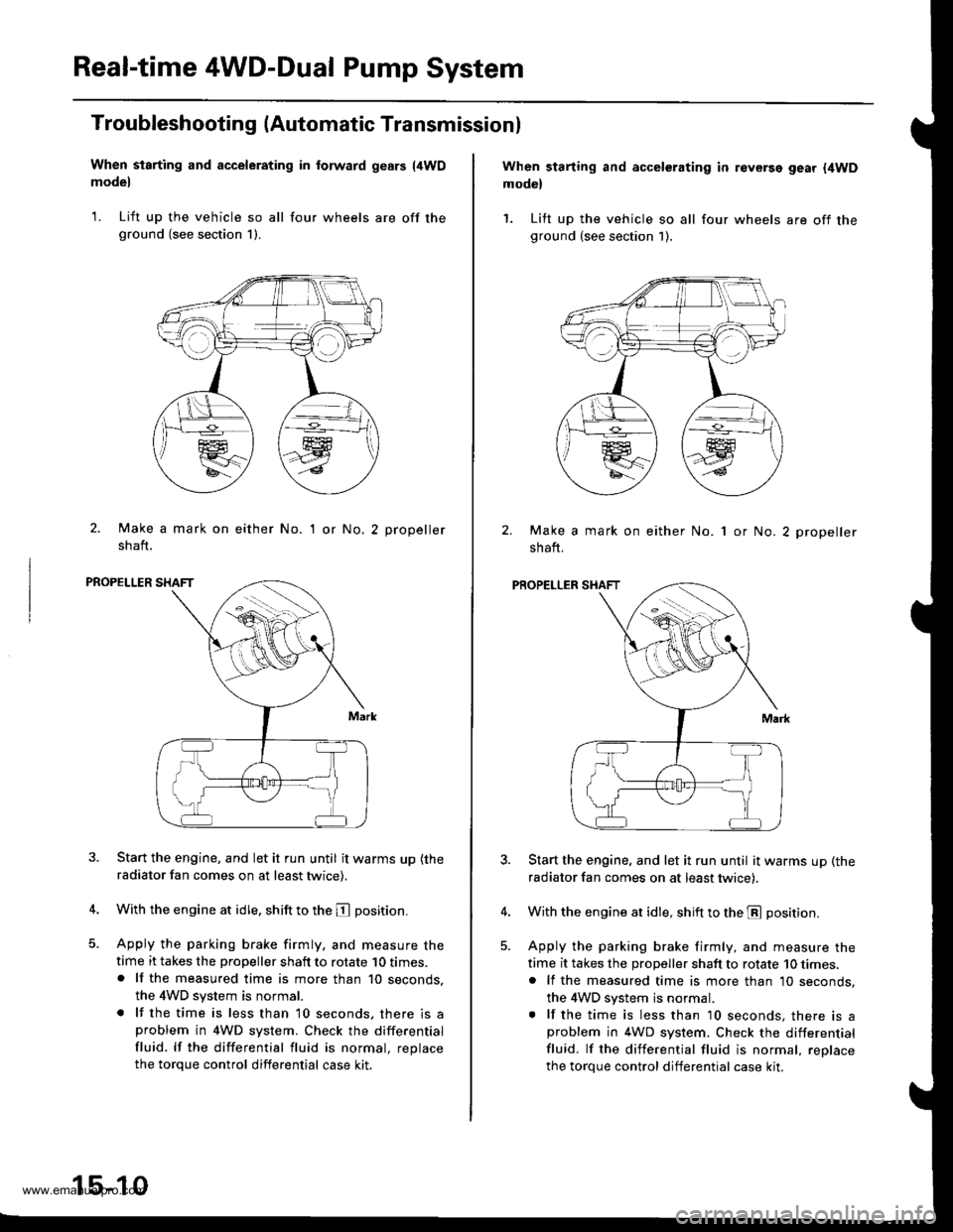
Real-time 4WD-Dual Pump System
Troubleshooting (Automatic Transmissionl
When starting and accelerating in forward gesrs {4WDmodel
1. Lift up the vehicle so all four wheels are off theground (see section 1).
2. Make a mark on either No.
shaft.
'I or No.2 propeller
PROPELLER SHAFT
Start the engine, and let it run until it warms up (the
radiator fan comes on at least twice).
With the engine at idle. shift to the E position.
Apply the parking brake firmly. and measure thetime it takes the propeller shaft to rotate 10 times.. lf the measured time is more than 10 seconds,
the 4WD system is normal.
. lf the time is less than 10 seconds, there is aproblem in 4WD system. Check the differential
fluid. lf the differential fluid is normal, replace
the torque control differential case kit.
15-10
When starting and accelerating in revGrsg gear {4WDmodel
1. Lift up the vehicle so all four wheels are off theground (see section 1).
Make a mark on either No.
shaft.
1 or No. 2 propeller
PROPELLER SHAFT
Start the engine. and let it run until it warms up (the
radiator fan comes on at least twicei.
With the engine at idle, shift to the E position.
Apply the parking brake firmly, and measure the
time it takes the proDeller shaft to rotate 10 times,. lf the measured time is more than 10 seconds,
the 4WD system js normal.. lf the time is less than 10 seconds, there is aproblem in 4WD system. Check the differential
fluid. lf the differential fluid is normal, reolace
the torque control differential case kit.
www.emanualpro.com
Page 802 of 1395
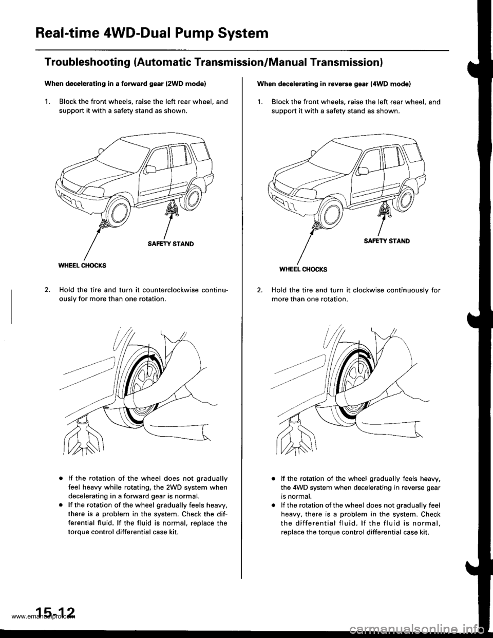
Real-time 4WD-Dual Pump System
Troubleshooting (Automatic Transmission/Manual Transmission)
Whon d6c6l6rating in a torward gear {2WD mode}
1. Block the front wheels, raise the left rear wheel. and
support it with a safety stand as shown.
Hold the tire and turn it counterclockwise continu-
ouslv for more than one rotation.
lf the rotation of the wheel does not gradually
feel heavy while rotating, the 2WD system when
decelerating in a forward gear is normal.
lf the rotation of the wheel gradually feels heavy,
there is a problem in the system. Check the dif-
ferential fluid, lf the fluid is normal, reDlace the
toroue control differential case kit.
WHEEL CHOCKS
15-12
When decelerating in reverse gear (4WD mod€)
1. Block the front wheels. raise the left rear wheel, and
suppo( it with a safety stand as shown.
Hold the tire and turn it clockwise continuouslv for
more than one rotation.
lf the rotation of the wheel gradually feels heaw.
the 4WD system when decelerating in reverse gear
is normal,
lf the rotation of the wheel does not gradually feel
heavy, there is a problem in the system. Check
the differential fluid. lf the fluid is normal.
reolace the torque control differential case kit,
WHEEL CHOCKS
www.emanualpro.com