Battery HONDA CR-V 1997 RD1-RD3 / 1.G Owner's Guide
[x] Cancel search | Manufacturer: HONDA, Model Year: 1997, Model line: CR-V, Model: HONDA CR-V 1997 RD1-RD3 / 1.GPages: 1395, PDF Size: 35.62 MB
Page 289 of 1395
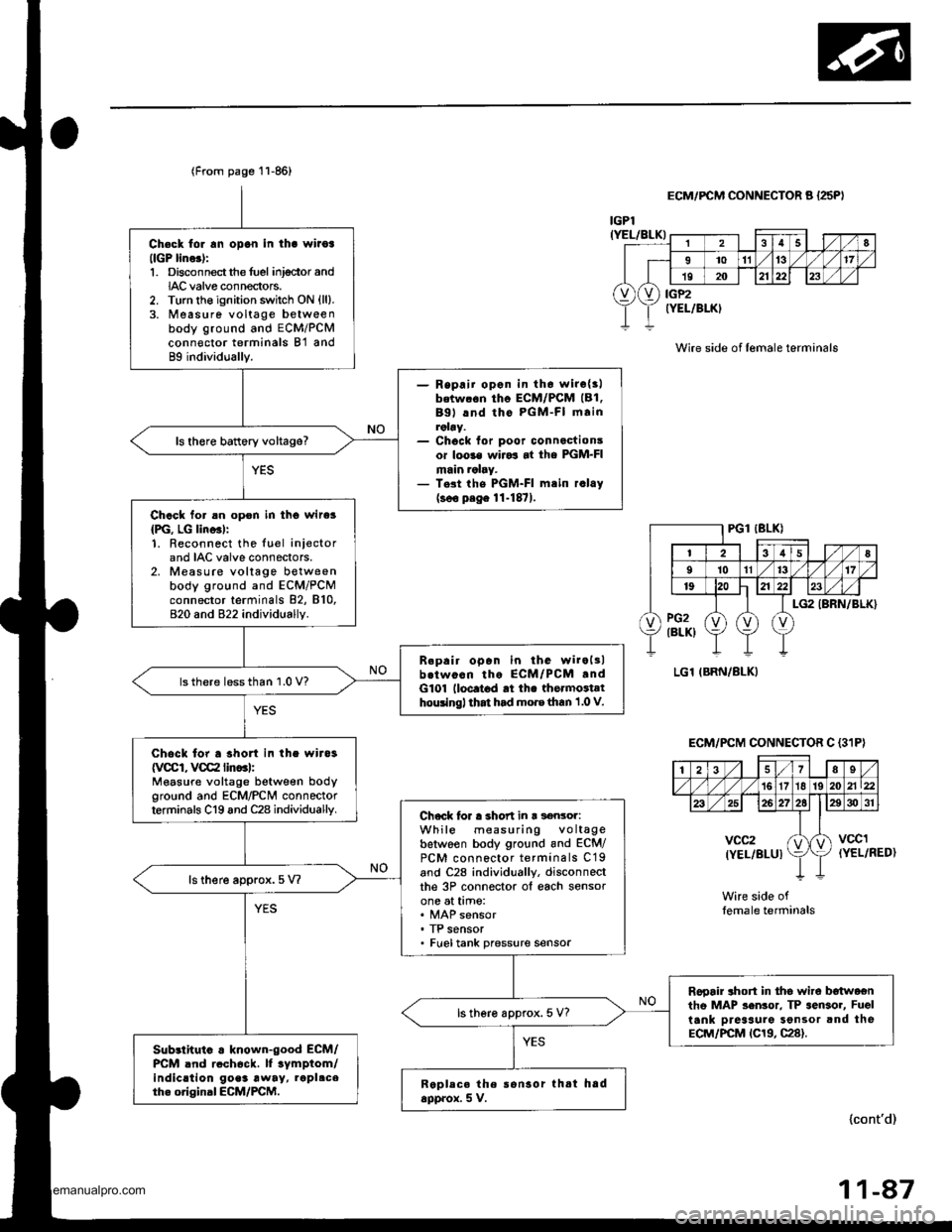
Ch€ck tor rn opon in tha wiioa(lGP lino.):1. Disconnectthe fuel inj€ctor andIAC valve connectors.2. Turn the ignition switch ON {ll}.3. Measure voltage betweenbody ground and ECM/PCMconn€ctor terminals B'l and89 individually.
- Repaii opon in th6 wirc{3lbetw.6n tho ECM/PCM (B1.
Bgl lnd tho PGM-FI mainroby.- Chock for poor connactionsor loo3€ wiJo3 at the PGM-FImain ralry.- T.st the PGM-FI mtin r.lay(soo p.ge 11-1871.
ls there battery voltage?
Chack for an opon in tho wire3
{PG, LG lino3l:1. Reconnect the luel iniectorand IAC valve connectors.2. Measure voltage betweenbody ground and ECM/PCMconnector terminals 82, 810,820 and 822 individually.
B.pair open in the wiroltlb.twocn tho ECM/PCM .ndG101 lloc.t6d rt th. thormoiathouingl that had mo.e than 1 .0 V.
lsthere lessthan 1.0 V?
Chock for a shon in the wira3
{VCCI, VCC2 lin..l:Measure voltage between bodyground and ECM/PCN4 connectorterminals C19 and C28 individuallv.Chock lor a short in r s€nsor:While measuring voltagebetwoen body ground and ECM/PCM connector terminals C19and C28 individually, disconneclthe 3P connector ol each sensorone at time:
. TP sensor. Fueltank pressure sensor
ls there approx.5 V?
Rooair ahort in tho wire b€twoentho MAP sen3or. TP sensor, Fuel
tank Dreaaure Sonsor and theECM/PCM tC19, C28).
ls there approx. 5 V?
Sub3lhuio . known-good ECM/PCM .nd rcch6ck. lf tymptom/indic.tion go.3 away, rapl.ceth. original ECM/PCM.Replece the ronsor thtt hadapprox. 5 V.
(From page 11-86)
lcont'd)
r
28
I1011't317
19202123
vXv) iiP2rELlBLK)
IGPl(YEL/BLK)
ECM/FCM CONNECTOR A {25PI
Wire side of lemale terminals
(YEL/RED)
Wire side oflemale terminals
ECM/PCM CONNECTOR C {3'IP}
| 2i37Es/'t61718 192021\22
26272elE30 31
vcc2(YEL/BLUIktvccl
11-47
www.emanualpro.com
Page 337 of 1395
![HONDA CR-V 1997 RD1-RD3 / 1.G Owners Guide
Vehicle Speed Sensor (VSSI
lPosoo-]-. |posol l-
97 modol:
The scan tool indicates Diagnostic Trouble Code {DTC} P0500*�or P0501*r: A range/perfor-
mance in the Vehicle Speed Sensor (VSS) circuit. HONDA CR-V 1997 RD1-RD3 / 1.G Owners Guide
Vehicle Speed Sensor (VSSI
lPosoo-]-. |posol l-
97 modol:
The scan tool indicates Diagnostic Trouble Code {DTC} P0500*�or P0501*r: A range/perfor-
mance in the Vehicle Speed Sensor (VSS) circuit.](/img/13/5778/w960_5778-336.png)
Vehicle Speed Sensor (VSSI
lPosoo-]-'. |posol l-'
'97 modol:
The scan tool indicates Diagnostic Trouble Code {DTC} P0500*'�or P0501*r: A range/perfor-
mance in the Vehicle Speed Sensor (VSS) circuit. * I ; A/T*2i Mfi
FCM CONNECTORS
A t32Pl
LG1(BRN/BLK)
NOTE: Do not use the engine to turn thofront wheels with th6 rear wheels on theground. The 4WD system will engage andthe vehicle will suddenlv Iurch forward.
Wire side ot female terminals
LGl
{BRN/BLKI
(cont'd)
11-135
The MIL hes boen roported on.DTC m501 is 3tor€d.
Problom verificetion:1. Test'drive the vohicle.2. Check the vehicle speed withthe scan tool,
lntormittent tailure, rystom b OKat thia timo. Chock tor poor con-nection3 or 10o3o wires rt C129lvss) .nd rr rhe Pcfr4,
ls the correct speed indicated?
Chock for an open in tho PiCM:1. Turn the ignition switch OFF.2. Block the rear wheels and setthe parking brake.3. Jack up the lront of the vehicleand support it with saletystands.4. Turn the ignition switch ON (ll).
5. Elock the right front wheel andslowly rotate the left trontwheel by hand.6. Measure voltage betweenPCM connector terminals C18and A9.
Substitulc a known-good PCMand .och6ck. It symptom/indicd.tion go.a away, .cplaco tho origi-nel FCM.
Doesthe voltage pulse 0 Vand 5 V or battery voltage?
Check for a .hort in the PCM:L Turn the ignition switch OFF.2. Disconnect the PCM con'nector C (31P).
3. Turn the ignition switch ON (ll).
4. Elock the right front wheeland slowly rotate the left front
5. Measure vohage between PCMconnector terminals C18 andA9.
Substituto e known-good PCMand rochock. f rymptom/indica-tion goos rwry, roplsc. tho origi-nalFCM.
Doesthe voltage pulse 0 Vand 5 V or battery voltage?
- Repair short in the wirebetween the PCM lC18l,cruise control unit, speodo-meter, and VSS,- Repair opon in the wirebetween the PCM {C181 .ndrhe vss.- f wire is OK. tost lho VSS l3oosoction 231.
www.emanualpro.com
Page 338 of 1395
PGM-FI System
Vehicle Speed Sensor (VSSI {cont'd}
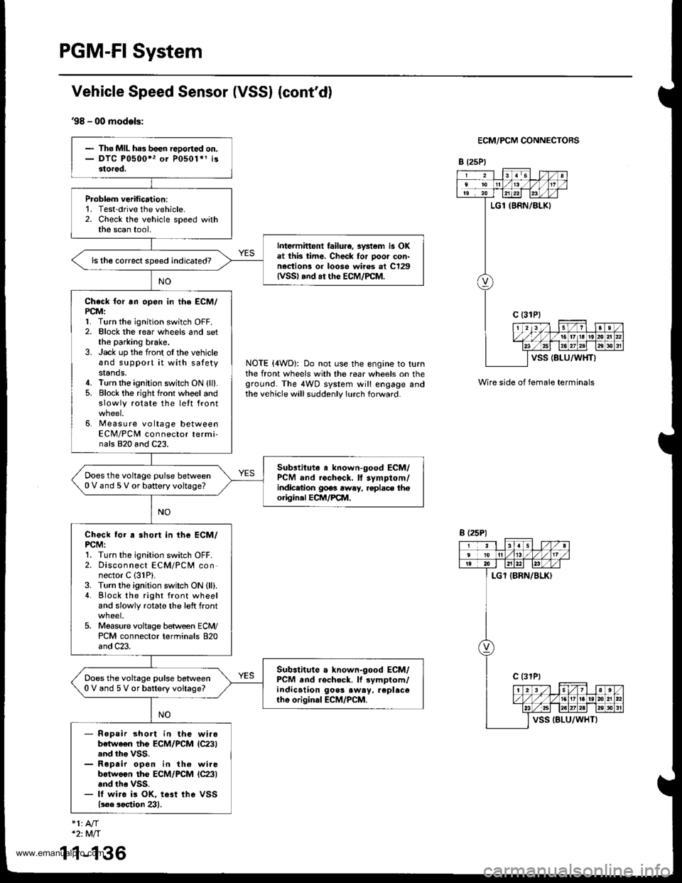
'98 - 00 models:
ECM/PCM CONNECTORS
B t25Pl
NOTE (4WD): Do not use the engine to turnthe front wheels with the rear wheels on theground. The 4WD system will engage andthe vehicle will suddenly lurch forward.
Wire side of female terminals
- The MIL ha3 been reDoned on.- DTC P0500" or P0501*1 i33torod.
Probl6m verification:1. Test-drive the vehicle.2. Check the vehicle speed withthe scan tool,
Intermittont failu.e, svstem is OKat thk time. Check for poor con-nection! or loose wiros at C129lvss) .nd ar the EcM/PcM.
ls the correct speed indicated?
Check for rn open in the ECM/PCM:l� Turn the ignition switch OFF.2. Elock the rear wheels and setthe parking brake.3. Jack up the front oI the vehicleand support it with satetystands.4. Turn the ignition switch ON {ll}.5. Block the right front whoel andslowly rotate the lett front
6. Measure voltage betweenECM/PCM connector termi-nals 820 and C23.
Substitute a known-good ECM/PCM and rochock. ll symptom/indicetion 9063 away, .oplace th€origin.l ECM/PCM.
Does the voltage pulse between0 V and 5 V or battery voltage?
Check for a short in the ECM/PCMI1. Turn the ignition switch OFF.2. Disconnect ECM/PCM connector C 131P).3. Turn the ignition swilch ON {ll).4. Block the right front wheeland slowly rotate the left front
5. Moasure voltage between ECM/PCM connector terminals 820and C23.
Sub.titute a known-good ECM/PCM and rschock. It rymptom/indication goos .w.y. replecerhe original ECM/PCM.
Does the voltage pulse betlveen0 V and 5 V or battery voltage?
- R.pair short in the wirobetwe€n the ECM/PCM lC23).nd tho VSS.- Roprir open in th6 wirebotweon the ECM/PCM lc23land th6 vss.- It wirc is OK, te3t ihe VSS(!€e soetion 23).
B (25P)
1
*2:Mft
1-136
www.emanualpro.com
Page 356 of 1395
The MIL has boen r.ported on.DIC Pl 508 b 3tored.
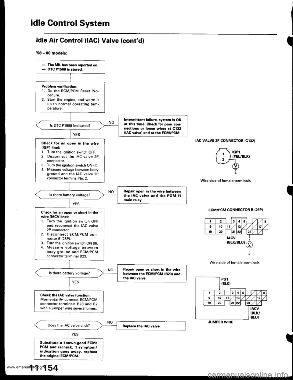
Problem veritication:L Do the ECM/PCM Reset Pro-cedure.2. Start the engine, and warm itup to normal operating tem-perature.
Int€rmittent failure, systom is OKal lhis timo. Check lor poor con-nections or looro wirca at C132(lAc vrlvel and .t rho EcM/PcM.
ls DTC P1508 indicated?
Chock tor an open in the wir6llGPl linel:1. Turn the ignition switch OFF.2. Disconnect the IAC valve 2Pconnector,3. Turn the ignition switch ON (ll).4. Measure voltage between bodyground and the IAC valve 2Pcon nector termina I No, 2.
Repair opon in the wira botwoonthe IAC valve and tho PGM-FImain aalay.
Check tor an open or short in thewire (IACV linel:1. Turn the ignition switch OFFand reconnect the IAC valve2P connector.2. Disconnect ECM/PCM con-nector B {25P).3. Turn the ignition switch ON {ll}.4. Measure voltage betweenbody ground and ECM/PCMconnector terminal 823.
Ropair open or short in thg wirebetween tho ECM/FCM lB23l andthe IAC valve.
ls there battery voltage?
Check the IAC valve func,tion:Momentarily connect ECM/PCMconnector terminals 823 and 82with a jumper wire several times.
Does the IAC valve click?
Subslitute . known-good ECM/PCM .nd rechock. lf symptom/indication goes aw.y, replac.th€ original ECM/PCM.
ldle Air Control (lAC) Valve {cont'd}
'98 - 00 models:
IAC VALVE 2P CONNECTOR {C132I
F rcpt*l tYELrBLxlI2/'-- rf)
Y
Wire side ot fem.le terminals
ECM/PCM CONNECTOR B (25PI
Wire side of female torminals
258
9'to1l13t7
1920212223
tAcv(BLK/BLUIv
PG1{BLKI
12 | t3 4 58
910 111317
1920 | 121)22
tAcv(BLK/
BLU)JUMPER WIRE
www.emanualpro.com
Page 359 of 1395
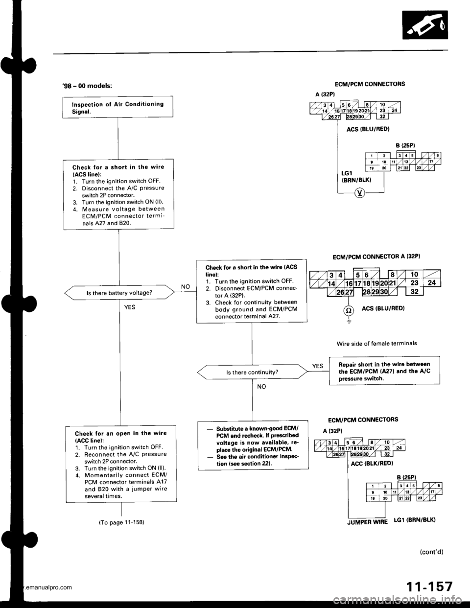
'98 - 00 models:ECM/PCM CONNECTORS
ECM/PCM CONNECTOR A (32PI
Wire side of female terminals
ECM/PCM CONNECTORS
A (32P1
ACC (BLK/REOI
LG1 (BRN/BLKI
{cont'd)
11-157
A {32P1
Check for a shott in the wire
{ACS linel:1. Turn the ignition switch OFF.
2. Disconnect the A/C Pressureswitch 2P connector.3. Turn the ignition switch ON (ll)
4. Measure vo ltage betweenECM/PCM connector terml
nals A27 and 820.
Check tor . short in the wire IACSlinel:1. Turn the ignition switch OFF.
2. Disconnect ECM/PCM connec-tor A (32P).
3. Check for continuity betweenbody ground and ECM/PCMconnector terminal A27.
ls there battery voltage?
R.oak short in the wile between
rhe ECM/PCM (A271 and the A/C
Dressure switch.ls there continuitv?
Sub6titute a known{ood ECM/
rcM and recheck. lf pte6cribed
voltage i3 now available, re'pl.ce the origioal ECM/rcM.See ih6 air conditioner inspec-
tion (s6e section 221.
Check for an open in the wire(ACC line):'1. Turn the ignition switch OFF.
2. Reconnect the A/C Pressureswitch 2P conneclor.3. Turn the ignition switch ON (ll).
4. Momentarily connect ECM/PCM connector terminals A17
and 820 with a jumPer wireseveralllmes,
{To page 11 158)JUMPER WIRE
www.emanualpro.com
Page 361 of 1395
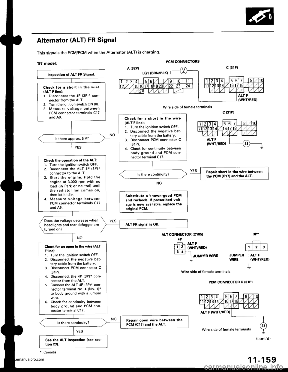
Alternator (ALT) FR Signal
This signals the ECM/PCM when the Alternator (ALTI is charging.
,97 modet: PCM GONNECTORS
wire side of female terminals
ALT CONNECTOR (C1O5I
lPr-F- ALT F
lll2llw|{frREDl|3.r-'l-
lruueen wne
c (31P|
wire side ol f€male terminals
PCM CONNECTOR C I31P)
3Pr
JUMPERWIRE
Inspection ot ALT FR Signal.
Check lor a short in the wire
{ALT F line}:1. Disconnect the 4P 13Pi* connector from the ALT.2. Turn the ignition switch ON (ll)
3, Measure voltage betweenPCM connector terminals C17
and A9.Check for a short in the wire(ALT F linel:1. Turn the ignition switch OFF.2. Disconnect the negative bat'tery cable from the battery.3. Disconnect PCM connector C(31P).
4. Check for continuity betweenbody ground and PCM connector terminal C17.
ls there approx. 5 V?
Check th€ ope.ation of the ALT:
1. Turn the ignition switch OFF2. Reconnect the ALT 4P {3Pi*connector to the ALT.3. Start the engine. Hold theengine at 3,000 rpm with no
load (in Park or neutral) untilthe radiator fan comes on,
then let it idle.4. Measure voltage betweenPCM connector terminals C17and A9.
Ropeir short in the wir6 betweonthe PCM lC17l and the ALT.
Substitut. a known-good PCM
and recheck. lf prescribed volt-
age is now availablo, replace the
originalPCM.
Does the voltage decrease when
headlights and rear defogger are
turned on?ALT FR signal b OK.
Ch€d( for an op€n in tho wire IALTF linel:1. Turn the ignition switch OFF.2. Disconnect the negative bat-tery cable lrom the battery.3. Disconnect PCM connector C(31P).
4. Disconnect the 4P (3P)* con-nector lrom the ALT.5. Connect the ALT 4P (3P)* con-nector terminal No. 4 (No. 1)*to body ground with a iumper
6. Check for continuity betweenbody ground and PCN4 con'nector terminal Cl7.
Repair open wi.e between thePCM lCl7l and the ALT.ls there continuity?
ALT F IWHT/REDI
Wire side of female terminals
1 1-159
www.emanualpro.com
Page 362 of 1395
![HONDA CR-V 1997 RD1-RD3 / 1.G Owners Guide
ldle Gontrol System
Alternator (ALT) FR Signal (contdl
98 - 00 modols:
ALT CONNECTOR (C1I}5I
4P
rH] Arr FllltwHr/REo)l3laF1
I JUMPER WIRE JUMPER+ WIRE
ECM/PCM CONNECTORS
Wire side of female termi HONDA CR-V 1997 RD1-RD3 / 1.G Owners Guide
ldle Gontrol System
Alternator (ALT) FR Signal (contdl
98 - 00 modols:
ALT CONNECTOR (C1I}5I
4P
rH] Arr FllltwHr/REo)l3laF1
I JUMPER WIRE JUMPER+ WIRE
ECM/PCM CONNECTORS
Wire side of female termi](/img/13/5778/w960_5778-361.png)
ldle Gontrol System
Alternator (ALT) FR Signal (cont'dl
'98 - 00 modols:
ALT CONNECTOR (C1I}5I
4P
rH] Arr Fl'l'ltwHr/REo)l3laF1
I JUMPER WIRE JUMPER+ WIRE
ECM/PCM CONNECTORS
Wire side of female terminals
ECM/PCM CONNECTOR C {31PI
Wire side of female terminals
Wire side of female terminals
ECM/PCM CONNECTOR C {31P}
": Canada
1 1-160
B (25P)
Insp€ction of ALT FR Signsl.
Check fo. a shon in th. wire {ALTF linel:1. Disconn6ct the 4P (3P)* con-nector from the ALT.2. Turn the ignition switch ON {ll).3. Measure voltage between ECM/PCM connector terminals C5and 820.Ch€ck for a sho.t in iho wirc lAlTF lino):1. Turn the ignition switch OFF.2. Disconnecl the negative bat,tery cable from the battery.3. Disconnect ECM,PCM connec-torC (31P).
4. Check for continuity betwoenbody ground and ECM/PCMconnector terminal c5.
ls there approx. 5 V7
Check the opcration of the ALT:1. Turn the ignitioo switch OFF.2. Reconnect rhe ALT 4P (3P)*connector to the ALT.3. Start the engine. Hold theengine at 3,000 rpm with noload (in Park or neutral) untilthe radiator lan comes on,then let it idle.4. Measure voltage between ECM/PCM connector terminals C5and 820.
Roprir lhort in tho wirc bstweentho ECM/PCM {Csl and the ALT.
Substitut. r known-good ECM/PCM and roch.ck. It Droscrib.dvoltage b now lvrilabls, .eplaccth. o.igin!l ECM/PCM.
Does the voltage decrease whenheadlights and rear defogger areturned on?ALT FR 3ignol is OK,
Chock lor an opon in tha wire (ALTF linel:1. Turn the ignition switch OFF.2. Disconnect the negative bat-tery cable from the battery.3. Disconnect ECM/PCM con-nector C (31P).4. Disconnect the 4P 13P)* con,nector from the ALT.5. Connect the ALT 4P {3P)* con-nector terminal No. 4 1No. 1)*to body ground with a jumper
6. Check for continuity betwe€nbody ground and ECM/PCMconnector terminal C5.
Rsprir opan wiro batw.en thoECM/PCM lcsl .nd th. ALT.ls there continuity?
AI.T F IWHT/REDI
ALT F {WHT/REDI
Wire side ot Iemale terminals
www.emanualpro.com
Page 363 of 1395
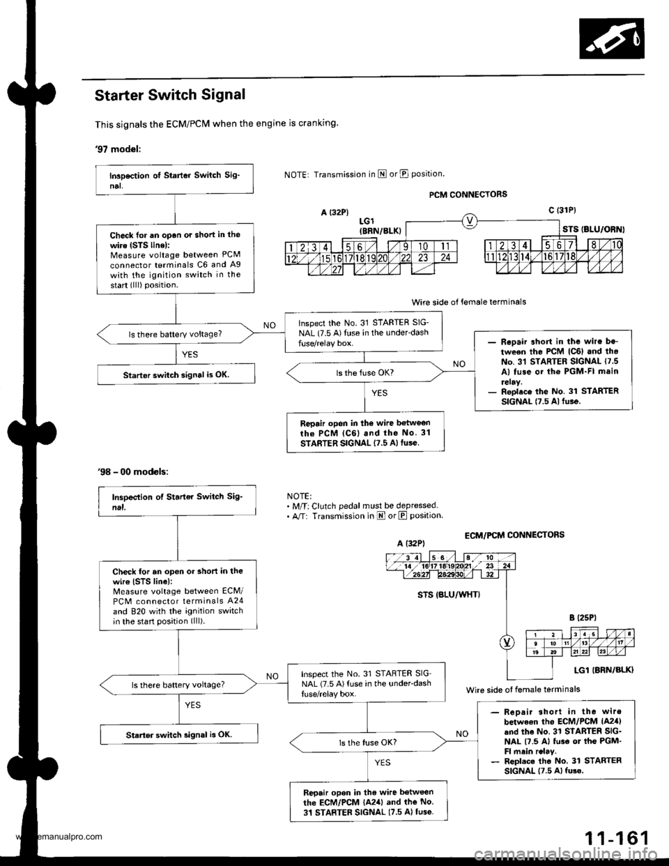
Starter Switch Signal
This signals the ECM/PCM when the engine is cranking.
'97 model:
A {32P}
'98 - 00 models:
Transmission in E or E position.
LGl(BBN/BLK)
PCM CONNECTORS
Wire side of female terminals
ECM/PCM CONI{ECTORS
STS (BLU/ORNI
c t31P)
NOTE:. M/T: Clutch pedal must be depressed.. A/T: Transmission in E orE position
Check for an opan ot short in the
wire (STS linel:Measure voltage between PCM
connector terminals C6 and Ag
with the ignition switch in the
start (lll) position.
lnspect the No. 31 STARTER SIG-
NAL (7.5 A)Illse in the under'dashls there battery voltage?- Reoair short in the wire be-
tween the PCM lc6l and th.No. 31 STARTER SIGNAL 17 5A) tuse ot the PGM-FI main
reray.- Reolace the No. 31 STARTERSIGNAL t7.5 Altu.e.
Starter swiich signal i3 OK.
Repair opon in the wire betweonrh6 PCM lc6l and the No 31
STARTER SIGNAL 17.5 A)fuse.
A (32P)
Wire side oI female terminals
Check tor an open or short in thewir€ (STS line):Measure voltage between ECM/
PCM connector terminals A24
and 820 with the ignition switchin the start position (lll).
Inspect the No. 31 STARTER SIGNAL (7.5 A){use in the under-dashls there battery voltage?
- Reoair shorl in the wire
betwe€n the ECM/PCM lA2,fland the No, 31 STARTER SIG-NAL t7.5 Al tu3€ ot the PGM'Fl main rclay.- Repl.c. tho No. 31 STARTERSIGNAL 17.5 Al fu3e.
Starter switch 3ignal is OK.
Repair opon in tho wire between
the ECM/PCM {A241 and the No
31 STARTER SIGNAL (7.5 A) tu3e
1 1-161
www.emanualpro.com
Page 364 of 1395
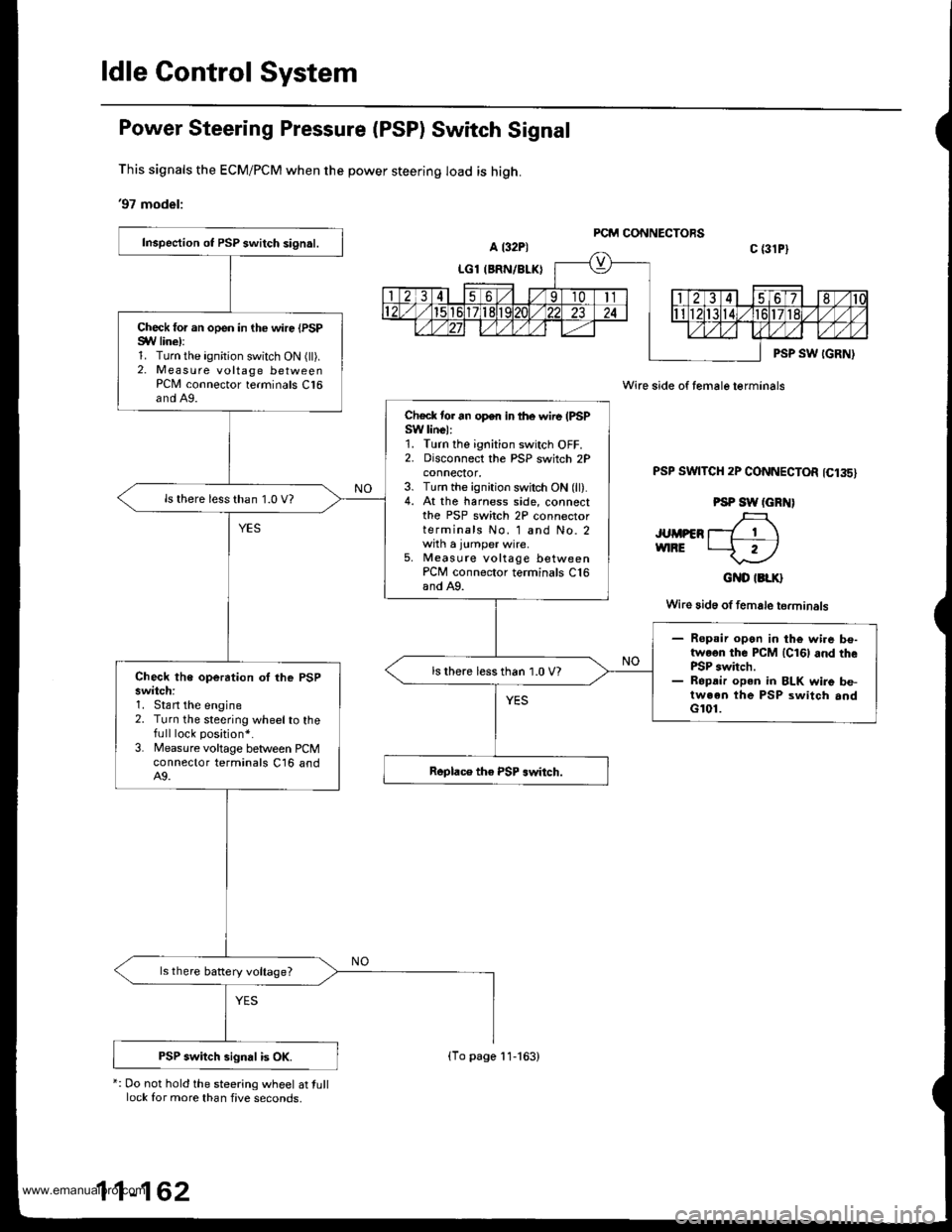
ldle Gontrol System
Power Steering Pressure (PSP) Switch Signal
This signals the ECM/PCM when the power steering load is high.
'97 model:
*: Do not hold the steering wheel at tulllock for more than five seconds,
Wire side of female terminals
PSP SWTTCH 2P CONNECTOR 1C135)
PSP SW (GRN)
JUMPER T_7 1 \vnRE t--f r)
GND IBLK}
Wire 3id6 of female terminals
Inspection ot PSP switch signal.
Check for an open in the wire {PSPSYV line):1. Turn the ignition switch ON (ll).2. Measure voltage betweenPCN4 connector terminals C16and A9.
Check tor an open in lhe wire (PSPSW linel:1. Turn the ignition switch OFF.2. Disconnect the PSP switch 2Pconnecror,3. Turn the ignition switch ON (ll).4. At the harness side, connectthe PSP switch 2P connectorterminals No. 1 and No. 2with a jumper wire.5, Measute voltage betweenPCM connector terminals C16and A9.
ls there less than 1.0 V?
- Ropsir open in the wi.e be-twoon the PCM lcl6l and thePSP switch.- Ropdir open in BLK wire be-tween the PSP switch andG101.
ls there less than 1.0 V?Check the operation oI lhe PSPswitch:1. Stan the engine2. Turn the steering wheelto thefull lock position*.
3. Measure voltage between PCMconnector terminals C16 andA9.
ls there battery voltage?
PSP switch signal is OK.(To page 11-163)
www.emanualpro.com
Page 366 of 1395
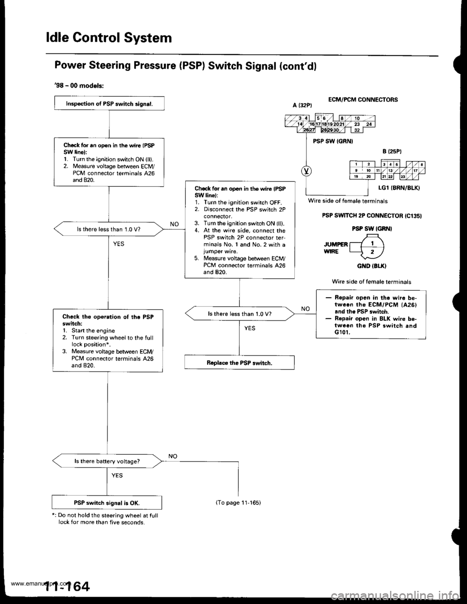
ldle Control System
Power Steering Pressure (PSP) Switch Signal (cont'dl
'98 - 00 models:
*: Do not hold the steering wheel at lulllock for more than five seconds.
ECM/FCM CONNECTORS
PSP SwlTCH 2P CONNECTOR ICl35}
PSP SW IGRNI
JUMpER f-7 T \wtRE L-5 rl
GND (3LX}
Wire side of lemale terminals
Inspection of PSP swilch 3ignal.
Ch€ck tor rn opon in the wire (PSP
SW line):1. Turn the ignition switch ON {ll).2. Measure voltage betlveen ECM/PCM connector terminals 426and 820.
Chock for an open in the wire IPSPSW lin€):1. Turn the ignition switch OFF.2. Disconnect the PSP switch 2Pconnector,3. Turn the ignition switch ON (ll).4. At the wire side. connect thePSP switch 2P connector terminals No. 1 and No.2 with a
5. Measure voltage between ECM/PCM connector terminals 426and 820.
ls there less than 1.0 V?
- Ropai. open in the wire be-tweon th6 ECM/PCM (A26)
and th6 PSP .witch.- R6p.ir open in BLK wire be-tween tho PSP 3witch andG 101,
lsthere less than 1.0 V?Check the op€ration of the PSPswitch:1. Stan the engine2. Turn steering wheel to the fulllock position*.3. Measure voltage b€tween ECM/PCM connector terminals A26and 820.
ls there battery voltage?
PSP switch signal is OK.
Wire side of female terminals
11-164
(To page 11-165)
www.emanualpro.com