Battery HONDA CR-V 1997 RD1-RD3 / 1.G Manual PDF
[x] Cancel search | Manufacturer: HONDA, Model Year: 1997, Model line: CR-V, Model: HONDA CR-V 1997 RD1-RD3 / 1.GPages: 1395, PDF Size: 35.62 MB
Page 659 of 1395

L
Input Test -'99 - 00 Models
Remove the gauge assembly from the dashboard {see section 20), and disconnect the 14P connector from the gauge
assembly (see section 23).
Inspect the connector and socket terminals to be sure they are all making good contact.
a lf the terminals are bent. loose, or corroded. repair them as necessary. and recheck the system.
. lf the terminals look OK, make the following input tests at the 14P connector.- lf a test indicates a problem, find and correct the cause, then recheck the system.- lf all the input tests prove OK, but the indicator is faulty, replace the printed circuit board.
GAUGE ASSEMBLY 14P CONNECTOR
Wire side of female terminals
CavityWire
ColorTest ConditionTest: Desired ResuhPossible Caus6
{lf resutt is not obtainod)
1YEL
lgnition switch ON (ll)Check for voltage to ground:
There should be battery voltage.
. Blown No.25 (7.5 A) fuse in the
under-dash fuse/relay box. An open in the wire
2RE D/BLK
Combination light
switch ON and dash
lights brightness con-
trol dial on full bright
Check for voltage between No. 2
and No.3 terminals:
There should be battery voltage.
Blown No. 47 {7.5 A) fuse in the
under-dash fuse/relay box
Faulty combination light switch
Faulty dash light brightness
controller
An open in the wire
5RED
BRNShift lever in ECheck for continuity to ground:
There should be continuity.
NOTE: There should be no continu-
ity in any other shift lever position.
. Faulty A/T gear position switch. An open in the wire7YELShift lever in E
'10BLUShift lever in E
LT BLU
lgnition switch ON (ll),
shift lever in E. and
Over-Drive is OFF bypressing O/D switch.
Check for continuity to ground:
There should be continuity.
Faulty O/D switch
Faulty A/T gear position switch
Faulty PCM
An open in the wire
8BLKUnder all conditionsCheck for continuity to ground:
There should be continuity
. Poor ground (G401)
. An open in the wire
9a:FI\|/Et| ta
lgnition switch ON (ll)
and shift lever in any
position except E
Check for voltage to groundl
There should be battery voltage
for two seconds after the ignition
switch is turned ON (ll). and less
than 1 V two seconds later.
. Faulty PCM. An open in the wire
11REDShift lever in SCheck for continuity to ground:
There should be continuity.
NOTE: There should be no conti-
nuity in any other shift lever posi-
Iton.
. Faulty A/T gear position switch. An open in the wire12WHTShift lever in E
BLI(BLU
Shift lever in ENOTE: Do not push
the brake pedal.
14LT GRN
lgnition switch ON (ll)
and shift lever in any
position except E and
E
Check for voltage to groundl
There should be about 5 V,
. Faulty PCM. An open in the wire
14-143
www.emanualpro.com
Page 661 of 1395
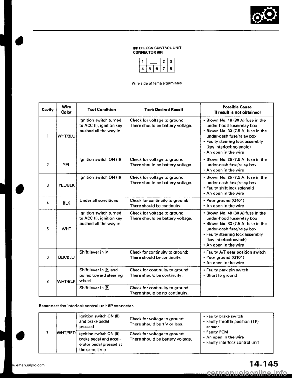
1?
4678
CavityWire
ColorTest CondhionTost: Desired RosultPossible Cause(lf result is not obtainedl
1WHT/BLU
lgnition switch turned
to ACC (l), ignition key
pushed all the way in
Check for voltage to ground:
There should be battery voltage.
Blown No. 48 {30 A} fuse in the
under-hood fuse/relay box
Blown No.33 (7.5 A) fuse in the
under-dash fuse/relay box
Faulty steering lock assembly
{key interlock solenoid)
An open in the wire
YEL
lgnition switch ON (ll)Check for voltage to ground:
There should be battery voltage.
Blown No.25 (7.5 A) fuse in the
under-dash fuse/relay box
An open in the wire
YEUBLK
lgnition switch ON (ll)Check for voltage to ground:
There should be baftery voltage.
Blown No. 25 (7.5 A) fuse in the
under-dash fuse/relay box
Faulty shift lock solenoid
An open in the wire
4BLKUnder all conditionsCheck for continuity to ground:
There should be continuity.
. Poor ground (G401)
. An open in the wire
5WHT
lgnition switch turned
to ACC (l), ignition key
pushed all the way in
Check for voltage to ground:
There should be battery voltage.
Blown No.48 (30 A) fuse in the
under-hood fuse/relay box
Blown No. 33 (7.5 A) fuse in the
under-dash fuse/relay box
Faulty steering lock assembly(key interlock switch)
An open in the wire
BLI(BLU
Shift lever in ECheck for continuity to ground:
There should be continuity,
Faulty Ay'T gear position switch
Poor ground (G101)
An open in the wire
8WHT/BLK
Shift lever in @ and
pulled toward steering
wneel
Check for continuity to ground:
There should be continuity.
Faulty park pin switch
Shon to ground
Shift lever in ECheck for continuity to ground:
There should be no continuity.
Wire side of female terminals
Reconnect the interlock control unit 8P connector.
14-145
7WHT/RED
lgnition switch ON (ll)
and brake pedal
presseo
Check for voltage to ground:
There should be 1 V or less.
Faulty brake switch
Faulty throttle position (TP)
sensor
Faulty PCM
An open in the wire
Faulty interlock control unit
lgnition switch ON (lll,
brake pedal and accel-
erator pedal pressed at
the same time
Check for voltage to ground:
There should be baftery voltage,
www.emanualpro.com
Page 663 of 1395
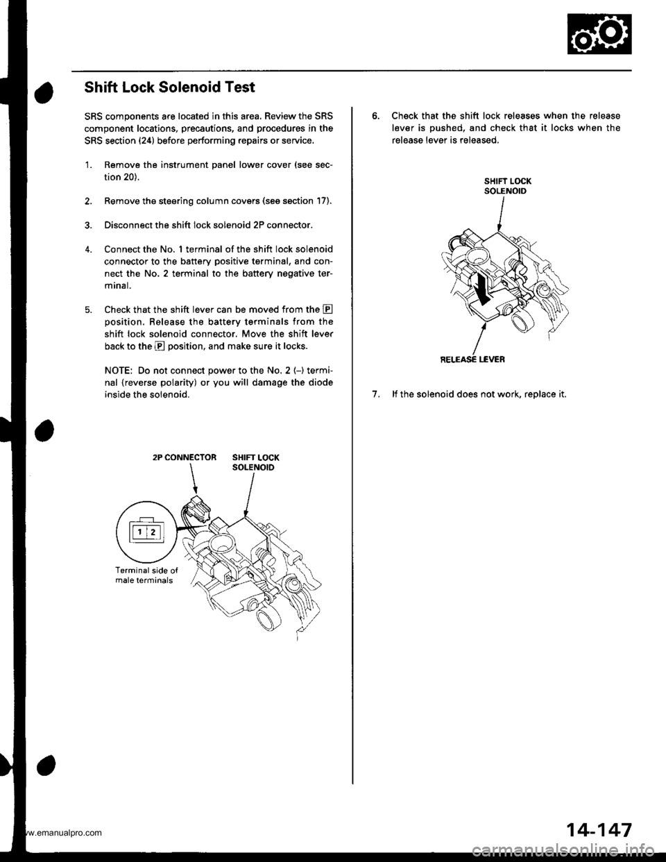
Shift Lock Solenoid Test
SRS components are located in this area. Review the SRS
component locations, precautions, and procedures in the
SRS section (24) before performing repairs or service,
'1. Remove the instrument panel lower cover (see sec-
tion 20).
2. Remove the steering column covers (see section 17).
3. Disconnect the shift lock solenoid 2P connector.
Connect the No. 1 terminal of the shift lock solenoid
connector to the battery positive tgrminal, and con-
nect the No. 2 terminal to the battery nogative ter-
mrnal.
Check that the shift lever can be moved from the E
oosition. Release the batterv terminals from the
shift lock solenoid connector. Move the shift lever
back to the E position, and make sure it locks.
NOTE: Do not connect power to the No. 2 (-) termi-
nal {reverse polarity) or you will damage the diode
inside the solenoid.
2P CONNECTOR SHIFT LOCK
6. Check that the shift lock releases when the release
lever is pushed, and check that it locks when the
release lever is released,
7. lf the solenoid does not work, replace it.
14-147
www.emanualpro.com
Page 685 of 1395

Transmission
Removal
@
2.
'1.
Make sure lifts. iacks, and safety stands aro placed
properly, and hoist brackets are attached to the col-
rest position on the engine lsee section 11.
Apply th€ parking brake and block the r€ar wheels,
so vehicls will noi roll off the stands and fall on you
while working under it.
NOTE: Use fender covers to avoid damaging painted
surfaces.
Disconnect the negative terminal, then disconnect
the positive terminal from the battery.
Remove the intake air duct and the air cleaner hous-
ing assembly,
Remove the starter cables. Remove the harness
clamp from the clamp bracket.
5.
STARTERCABLES
Remove the transmission ground cable terminal
and the radiator hose clamp lrom the transmission
hanger.
Disconnect the lock-up control solenoid valve con-
nector, then remove the harness clamp from the
clamp bracket.HARNESS CLAMP
RADIATOR HOSECLAMP
CONTROLSOLENOID VALVECONNECTOR
CLAMP
6. Disconnect the vehicle speed sensor (VSS), the coun-
tershaft speed sensor, and the A/T gear position
switch connectors.
A/T GEAR POSITIONSWITCH CONNECTOR
VEHICLE SPEEDSENSOR |VSS'
CONNECTORBfiACKET
SPEED SENSORCONNECTOR
7. Remove the transmission housing mounting bolts.
MOUNTING BOLTS
(cont'd)
14-169
www.emanualpro.com
Page 779 of 1395

26. Connect the vehicle speed sensor (VSS). the coun-
tershaft speed sensor. and the A,/T gear position
switch connectors,
VEHICLE SPEEO
SPEED SENSOACO'{NECTOR
Connect the lock-up control solenoid valve connec-
tor, then install the harness clamp on the clamp
bracket.
HARNESS CI-AMP
27.
RADIATOR HOSECLAMP
TRANSMISSIONGROUND CAB1ITERMINAL
LOCK-UP OONTROLSOLENOID VALVECONNECTOR
6x1.0mm12 N'm (1.2 kgi.m,8.? tbtftl
28.
29.
Instail the transmission ground cable terminal on
the transmission hanger, and install the radiator
hose clamp on the transmission hanger,
Connect the starter cables to the starter, and install
the harness clamD on the clamD bracket. Make sure
the crimped side of the starter cable ring terminal is
facing out.
STARTEBCABLE
STARTER CAAtf,
Install the air cleaner housing assembly and the
intake air duct.
Refill the transmission with ATF (see page 14-161).
Connect the battery positive terminal and negative
terminal.
Set the parking brake, Start the engine, and shift the
transmission through all gears three times.
Check the shift cable adjustment (see page 14-271]-.
Check the tront wheel alignment and adjust it if
needed (see section 18).
Let the engine reach normal operating temperature
(the radiator fan comes on) with the transmission in
E or N position, then turn it off and check the ATF
level {see page 14-160).
Perform a road test (see page 14-157 and 14-158).
30.
31.
34.
CLAMP BRACKET
37.
14-263
www.emanualpro.com
Page 957 of 1395
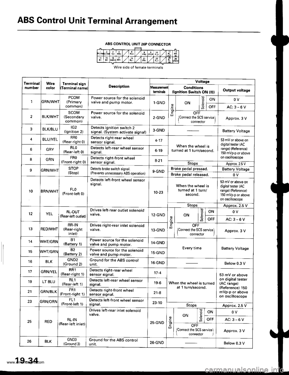
ABS Control Unit Terminal Arrangement
ABS CONTROL UNIT 26P CONNECTOR
Wire side of female terminals
TeiminalnumbelWiiecolorTerminal3ignTeiminalnamglDescription
Voltrge
tdminalsCondhions(lgnition Switch ON llll)Output voltago
1GRNn/VHTPCOM(Primary
common)
Power source for the solenoidvalve and pump motor.1-GNDON6
ONOV
OFFAC:3-6V
2BLI(WHTSCOM(Secondary
common)
Power source for the solenoid2-GNDOFF
lConnect the SCS seNice] connector IApprox.3 V
BLVBLU(lgnition 2)Detects ignition switch 2signal. (System activate signal)3-GNDBattery Voltage
4BLUA/ELRRO(Rear-right 0)Detocts right-rear wheelsensor srgnat.When the wheel isturned at 1 turn/second.
53 mV or above ondigitaltester (ACrange) {Beference)150 mvtrp or aboveon oscilloscope
GRYRLO(Rear-left 0)Detects left-rear wheel sensorsrgnat.6-19
8GRNFRO(Fronr-right 0)Detects right-front wheelsensor signal.8-21StopsApprox.2.5 VSTOP
{Stop)Detects bfake switch signal.(Prevents unnecessary ABS operation)9-GNDBrake pedal pressed.Battery Voltage
Brake Dedal released.OV
10BRN^/VHTFLO(Front-left 0)
Detects left-front wheel sensorsrgnal.
10-23
When the wheel isturned at 1 turn/second.
53 mV or above ondigitaltester lACrange) (Reference)
150 mvpp or aboveon oscilloscope
StopsADprox. 2.5 V
YELRL-oUT(Rearleft outlet)
Drives left-rear outlet solenoid12.GNDONONOV
OFFAC:3-6V
13RED^/vHTRR.IN(Rear-right
inlet)
Drives right-rear inlet solenoid13.GNDOFF
lConnect the SCS service\ connector IApprox. 3 V
14WHT/GRNB1(Baftery 1)Power source for the solenoidvalve and pump motor.14.GND
Every timeBattery Voltage82(Battery 2)Power source for the solenoidvalve and pump motor.15-GND
16BLKGND2(Ground 2)Ground for the ABS controlunit.16-GNDBelow 0.3 V
't7GRN/YELRR1(Rear-right 1)Detects right-rear wheelsensor signal.'t7 -4
When the wheel is turnedat l turn/second,
53 mV or aboveon digitaltester(AC range)(Reference) 150mVp-p or aboveon oscilloscope
19LT BLURL1(Rearieft 1)Detects left-rear wheel sensorsignal.19-6
GRN/BLKFR1(Front-right 1)Detects right-front wheelsensor srgnat.21-8
23GBN/ORNFL1{Front-left 1}Detects left-front wheel sensorsagnal.23-10StopsApprox. 2.5 V
REDRLI N(Rear-left inlet)
Drives left-rear inlet solenoid
25,GND
ON
=
-9ONOV
AC:3-6V
OFF
/Connect the SCS service] conneclor IApprox. 3 V
26BLKGND3(Gtound 3)Ground tor the ABS controluntI.26-GNDBelow 0.3 V
19-34
www.emanualpro.com
Page 958 of 1395
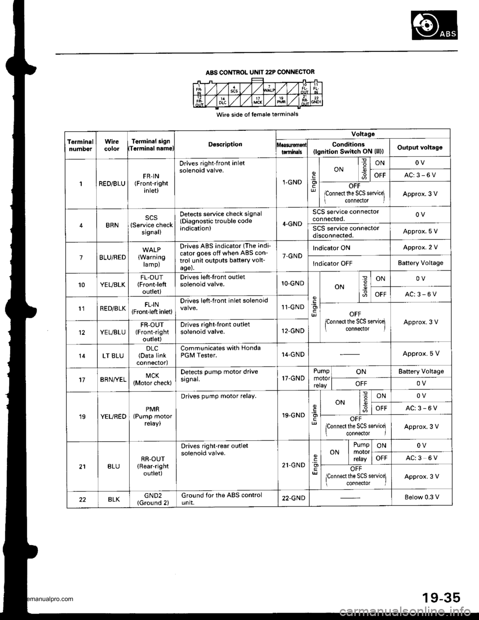
ABS CONTROL UNIT 22P CONNECIOR
Wire side ol lemale terminals
TerminalnumDerWirecolorTerminal 3i9nTerminal nameDescription
Voltage
Conditions(lgnition Switch ON (ll)lOutput voltagetominals
1RED/BLUFR-IN(Front-right
inlet)
Drives right-front inletsolenoid valve.
1-GND.9otur
ONIONOV
OFFAC:3-6V
OFF
lconnect the SCS servicel
connedor lApprox.3 V
BRN(Service checksignal)
Detects service check signal(Diagnostic trouble codeindication)4.GND
SCS service connectorconnected.OV
SCS service connectordisconnected.Approx. S V
7BLU/RED(Warning
ramp)
Drives ABS indicator {The indi-
cator goes off when ABS con-
trol unit outputs battery volt-age).
7.GND
lndicator ONApprox. 2 V
lndicator OFFBattery Voltage
10YEUBLKFL-OUT(Frontieft
outlet)
Drives left-front outletsolenoid valve.1O-GNDON
=
I
ONOV
OFFAC:3-6V
l'lRED/BLKFL-IN(Front-left inlet)
Drives left-front inlet solenoid11-GNDOFF
lconnect the SCS servicq connector lApprox.3 V
YEUBLUFR-OUT(Front-right
outlet)
Drives right-front outletsolenoid valve.12-GND
14LT BLU(Data linkconnectod
Communicates with HondaPGM Tester.14-GNDApprox. 5 V
17BRN/YELMCK(Motor check)
Detects PumP motor drivesignal.17-GNDPumpmotorrelay
ONBattery Vollage
OFFOV
19YEUREDPMR(Pump motorreray,
Drives pump motor relay.
19.GNDcl)
ON6IONOV
OFFAC:3-6V
OFFponnecl the SCS service]
connector IApprox.3 V
BLURR-OUT(Rear-right
outlet)
Drives right-rear outletsolenoid valve.
21.GND'a)
ONPumpmororrcray
ONOV
OFFAC:3 6V
OFF
lconnect the SCS service] connector lApprox.3 V
BLKGND2(Ground 2)Ground for the ABS controlunit.22.GNDBelow 0.3 V
19-35
www.emanualpro.com
Page 959 of 1395
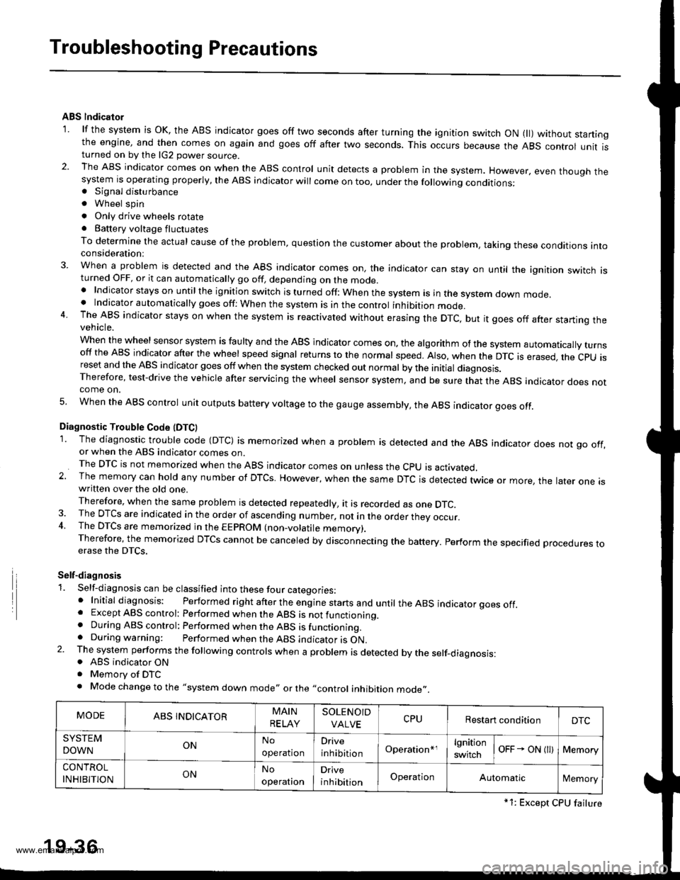
Troubleshooting Precautions
ABS lndicalor
1 lf the system is oK, the ABS indicator goes off two seconds after turning the ignition switch oN 1l) wathout staningthe engine, and then comes on again and goes off after two seconds. This occurs because the ABS control unit isturned on by the lG2 power source.2. The ABS indicator comes on when the ABS control unit detects a problem in the system. However, even thouoh thesystem is operating properly, the ABs indicator will come on too, under the following conditions:. Signal disturbance
. Wheel spin
. Only drive wheels rotate. Battery voltage fluctuates
To determine the actual cause of the problem, question the customer about the problem, taking these conditions intoconsideration:
3 When a problem is detected and the ABS indicator comes on, the indicator can stay on until the ignition switch isturned OFF, or it can automatically go off, depending on the mode.. Indicator stays on untilthe ignition switch is turned off: When the system is in the system down mode.. Indicator automatically goes off: When the system is in the control inhibition mode.4 The ABS indicator stays on when the system is reactivated without erasing the DTC, but it goes off after starting thevehicle.
When the wheel sensor system is faulty and the ABS indicator comes on. the algorithm of the system automatically turnsoff the ABS indicator after the wheel speed signal returns to the normal speed. Also, when the DTc is erased, the cpu isreset and the ABS indicator goes off when the system checked out normal by the initial diagnosis.Therefore, test-drive the vehicle after servicing the wheel sensor system. and be sure that the ABS indicator does notcome on.
5 When the ABS control unit outputs battery voltage to the gauge assembly, the ABS indicator ooes off.
Diagnostic Trouble Code (DTCI
1. The diagnostic trouble code (DTc) is memorized when a problem is detected and the ABS indicator does not go off,or when the ABS indicator comes on.The DTc is not memorized when the ABS indicator comes on unress the cpu is activated,2 The memory can hold any number of DTCs. However, when the same DTc is detected twice or more, the tater one iswritten over the old one.
Therefore, when the same problem is detected repeatedly, it is recorded as one DTC.3. The DTCs are indicated in the order of ascending number, not in the order they occur.4. The DTCS are memorized in the EEPROM (non-volatile memorv).Therefore, the memorized DTcs cannot be canceled by disconnecting the battery. perform the specified procedures toerase the DTCS.
Self-diagnosis
1. Self-diagnosis can be classified into these four categories:' Initial diagnosis: Performed right after the eng ine starts and untir theABS indicator goes off.. Except ABS control: Performed when the ABS is not functioning.. During ABS control: Performed when the ABS is functioning.. During warning: Performed when the ABS indicator is ON.2. The system performs the fo|owing contrors when a probrem is detected by the serf-diagnosis:. ABS indicator ON. Memorv of DTC. Mode changetothe "system down mode,, or the ,,control inhibition mode,,.
MODEABS INDICATORMAIN
RELAY
SOLENOID
VALVECPURestart conditionDTC
SYSTEM
DOWNONNo
operation
Drive
inhibitionOperation*rlgnition
switchoFF - ON l)Memory
CONTROL
INHIBITIONONNo
operal|on
Drive
inhibitionOperationAutomaticlMemory
*1: Except CPU failure
19-36
www.emanualpro.com
Page 964 of 1395
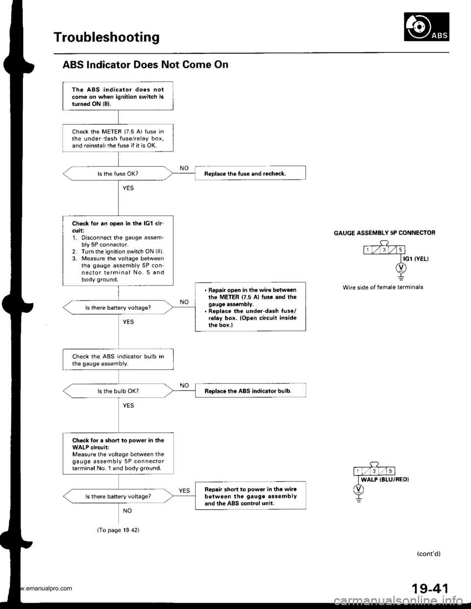
Troubleshooting
ABS lndicator Does Not Come On
The ABS indicator does notcome on when ignition switch isturnod ON lll).
check the METER {7.5 A} fuse inthe underCash fuse/relay box,and reinstaltthe fuse if it is OK.
Check for an open in the lcl ch-cuil:1. Disconnect the gauge assem-bly 5P connector.2. Turn the ignition switch ON (ll).
3. Measure the voltage betweenthe gauge assembly 5P con-nector terminal No. 5 andbody ground.
. Repair open in the wire betweenlhe METER {7.5 A) luse and thogauge assembly.. Reolece the under-dash fuse/relay box. (Opon circuit insidethe box.)
ls there battery voltage?
Check the ABS indicator bulb inthe gauge assembly.
Replace the ABS indicator bulb.
Check for a short to power in theWALP circuit:Measure the voltage between thegauge assembly 5P connectorterminal No. 1 and body ground.
Sepair short to power in the witeb€tween the gaug€ assemblyand the ABS control unil.ls there battery voltageT
Reolace the tuse and recheck.
(To page 19 42)
GAUGE ASSEMBLY 5P CONNECTOR
Wire side of female terminals
(cont'd)
19-41
www.emanualpro.com
Page 966 of 1395
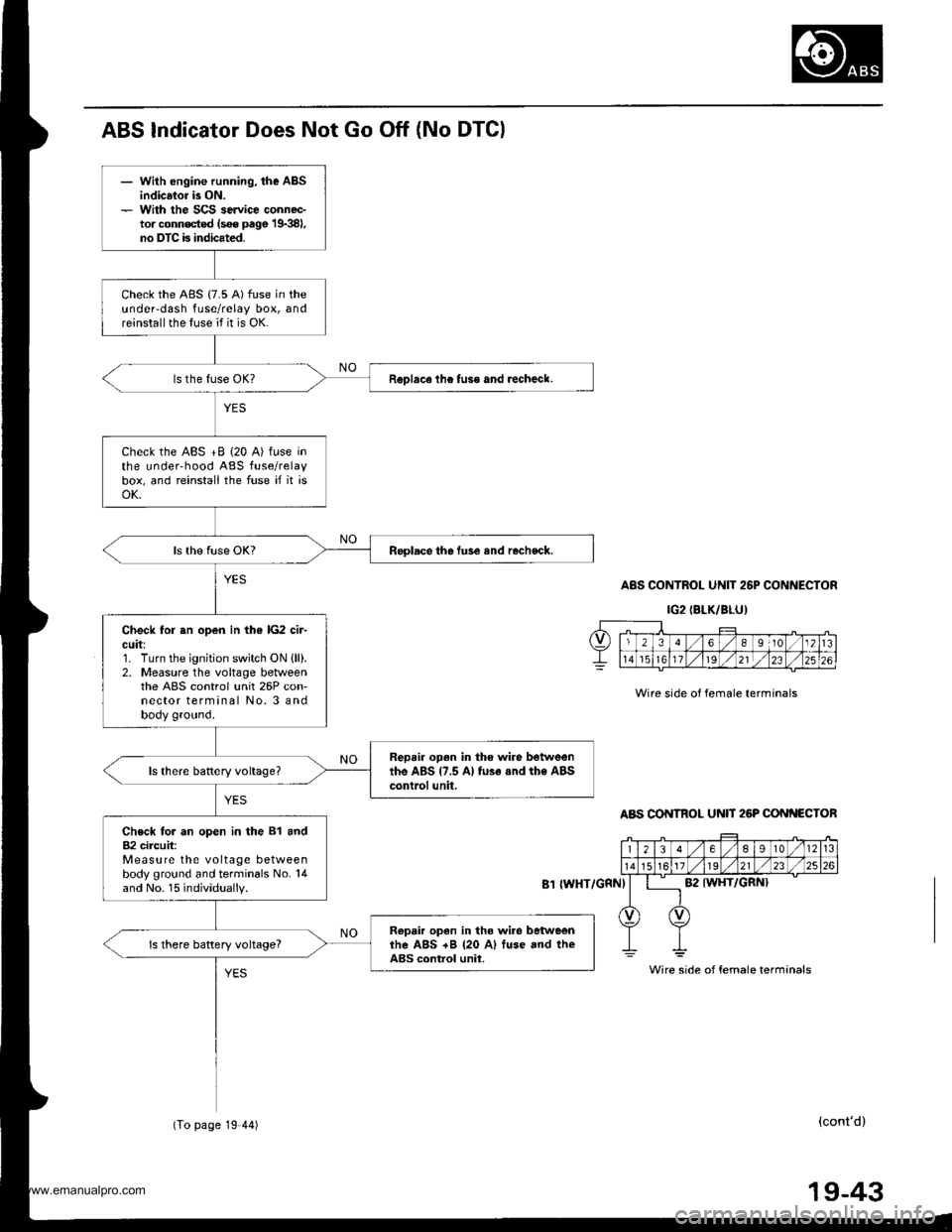
- With engine running, the ABSindicsior is ON.- With the SCS service connec-tor conn€cted (s€€ page 19381,no DTC is indicated.
Check the ABS {7.5 A) fuse in theundeFdash fuse/relay box, andreinstall the fuse if it is OK.
ReDlace lhe tuse and recheck.
Check the ABS +B (20 A) fuse inthe underhood ABS fuse/relaybox, and reinstall the fuse if it isoK.
Replace the fuse and rocheck.
Check for sn open in the lG2 cir-cuit:1. Turn the ignition switch ON {ll).2. Measure the voltage betweenthe ABS control unit 26P con-nector terminal No. 3 andbody ground.
Repair open in tho wire betweenthe ABS {7.5 A} fu3e .nd the ABScontrol unit,
Check for an open in the 81 and82 circuit:Measure the voltage betweenbody ground and terminals No. 14and No. 15 individually.
Ropair open in tho wi.e betweenrhe ABS +B {20 A) fuse and theABS control unit.is there battery voltage?
ABS Indicator Does Not Go Off (No DTGI
A8S CONTROL UNIT 26P CONNECTOR
IG2IBLK/BLU)
Wire side of female terminals
ABS CONTROL U N 26P CONf{ECTOR
{WHT/GRNI
(cont'd)
Wire side of female terminals
(To page 19 44)
19-43
www.emanualpro.com