piston ring HONDA CR-V 1997 RD1-RD3 / 1.G Owner's Guide
[x] Cancel search | Manufacturer: HONDA, Model Year: 1997, Model line: CR-V, Model: HONDA CR-V 1997 RD1-RD3 / 1.GPages: 1395, PDF Size: 35.62 MB
Page 796 of 1395
Description
Hydraulic Flow
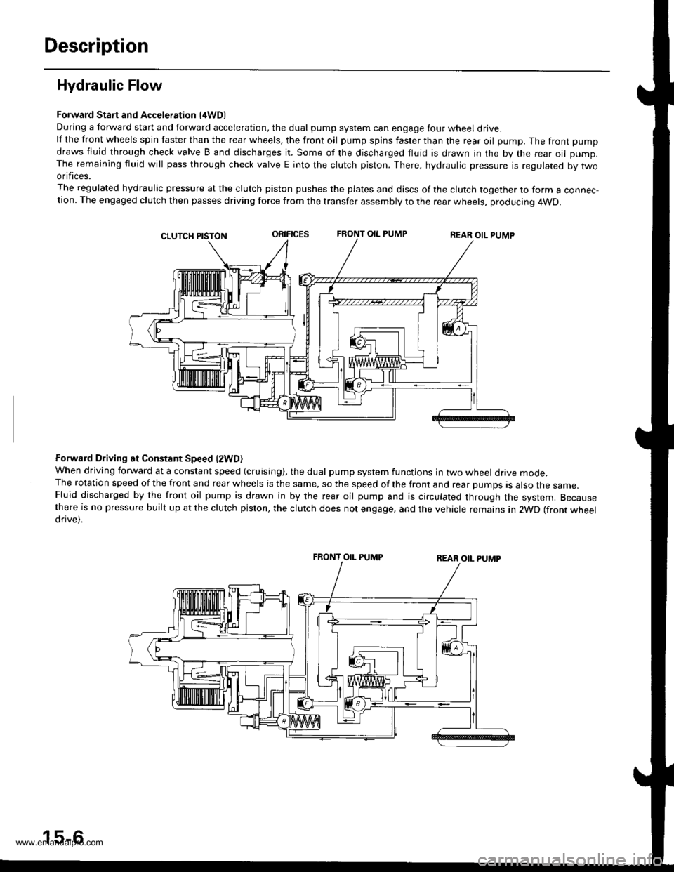
Forward Start and Acceleration l4WD)During a forward start and forward acceleration, the dual pump system can engage four wheel drive.lf the front wheels spin faster than the rear wheels, the front oil pump spins faster than the rear oil pump. The front pump
draws fluid through check valve B and discharges it. Some of the discharged fluid is drawn in the by the rear oil pump.The remaining fluid will pass through check valve E into the clutch piston. There, hydraulic pressure is regulated by twoorifices.
The regulated hydraulic pressure at the clutch piston pushes the plates and discs of the clutch together to form a connec-tion. The engaged clutch then passes driving force from the transfer assembly to the rear wheels, producing 4WD.
oRrFtcEsFRONT OIL PUMPREAR OIL PUMP
Forward Driving at Constant Speed lzWD)When driving forward at a constant speed (cruising), the dual pump system functions in two wheel drive mode.The rotation speed of the front and rear wheels is the same, so the speed of the front and rear pumps is also the same.Fluid discharged by the front oil pump is drawn in by the rear oil pump and is circulated through the system. Becausethere is no pressure built up at the clutch piston, the clutch does not engage, and the vehicle remains in 2WD (front wheeldrive).
FRONT OIL PUMP
15-6
www.emanualpro.com
Page 797 of 1395
Forward Deceleration l2WDl
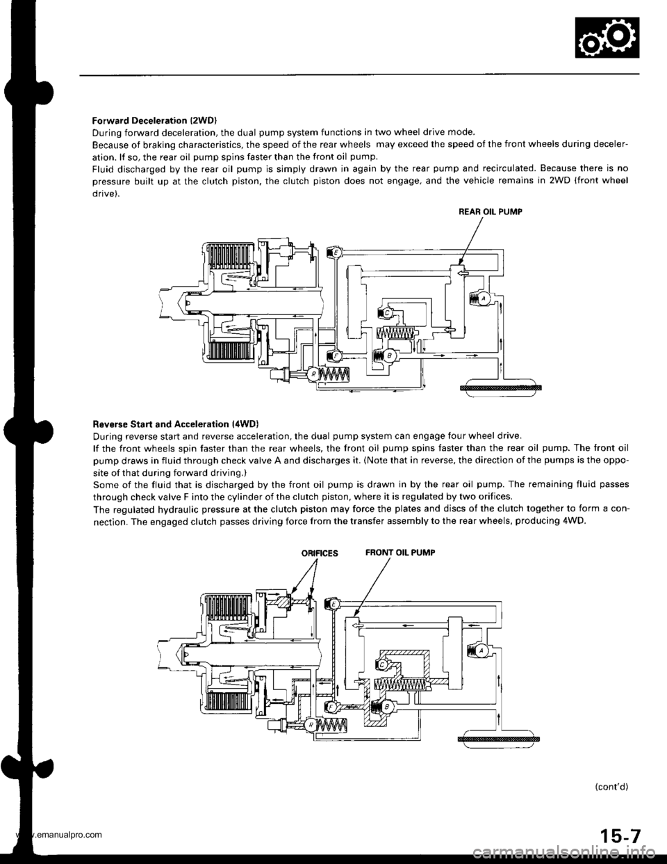
During forward deceleration, the dual pump system functions in two wheel drive mode.
Because of braking characteristics, the speed of the rear wheels may exceed the speed ol the front wheels during deceler-
ation. lf so, the rear oil pump spins faster than the front oil pump.
Fluid discharged by the rear oil pump is simply drawn in again by the rear pump and recirculated. Because there is no
pressure built up at the clutch piston. the clutch piston does not engage, and the vehicle remains in 2WD (front wheel
drive).
Reverse Start and Acceleration (4WD)
During reverse start and reverse acceleration, the dual pump system can engage four wheel drive.
lf the front wheels spin faster than the rear wheels, the front oil pump spins faster than the rear oil pump. The front oil
pump draws in fluid through check valve A and discharges it. {Note that in reverse, the direction of the pumps is the oppo-
site of that during forward driving.)
Some of the fluid that is discharged by the front oil pump is drawn in by the rear oil pump. The remaining fluid passes
through check valve F into the cylinder of the clutch piston, where it is regulated by two orifices.
The regulated hydraulic pressure at the clutch piston may force the plates and discs of the clutch together to form a con-
nectlon. The engaged clutch passes driving force from the transfer assembly to the rear wheels, producing 4WD.
oRtFtcEsFRONT OIL PUMP
{cont'd)
15-7
REAR OIL PUMP
www.emanualpro.com
Page 798 of 1395
Description
Hydraulic Flow (cont'dl
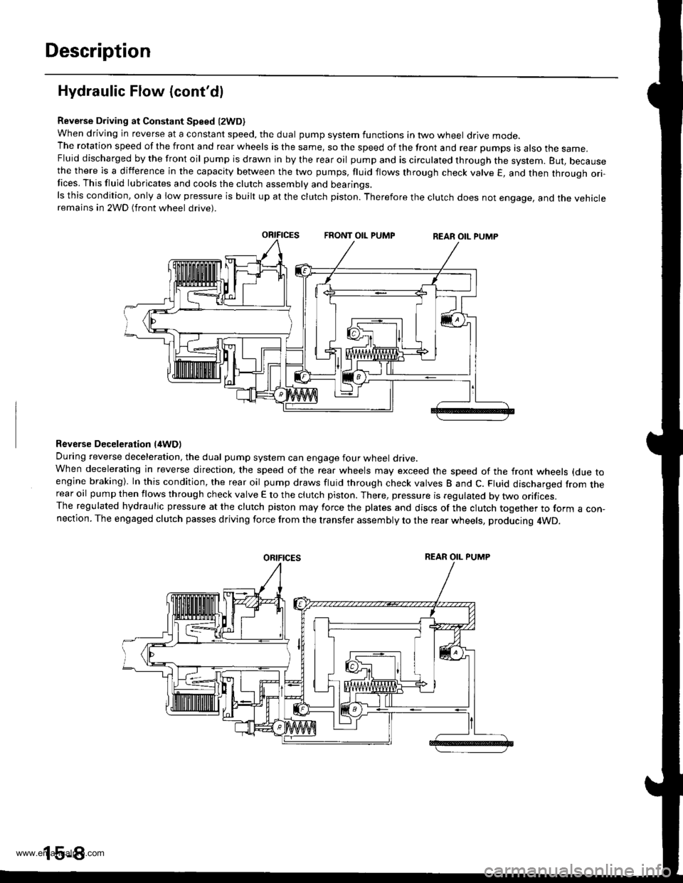
Reverse Driving at Constant Speed l2WD)when driving in reverse at a constant speed, the dual pump system functions in two wheel drive mode.The rotation speed of the front and rear wheels is the same, so the speed of the front and rear pumps is also the same,Fluid discharged by the front oil pump is drawn in by the rear oil pump and is circulated through the system. But, becausethe there is a difference in the capacity between the two pumps, fluid flows through check valve E, and then through ori-Iices. This fluid lubricates and cools the clutch assembly and bearings.ls this condition, only a low pressure is built up at the clutch piston. Therefore the clutch does not engage, and the vehicleremains in 2WD (front wheel drive).
Reverse Deceleration l/tWDl
During reverse deceleration, the dual pump system can engage four wheel drive.When decelerating in reverse direction, the speed of the rear wheels may exceed the speed of the front wheels (due toengine braking). In this condition, the rear oil pump draws fluid through check valves B and C. Fluid discharged from therear oil pump then flows through check valve E to the clutch piston. There, pressure is regulated by two orifices.The regulated hydraulic pressure at the clutch piston may force the plates and discs of the clutch together to form a con,nection. The engaged clutch passes driving force from the transfer assembly to the rear wheels, producing 4WD.
oRtFtcEsREAR OIL PUMP
www.emanualpro.com
Page 799 of 1395
Thermal Switch Operation l2WD)
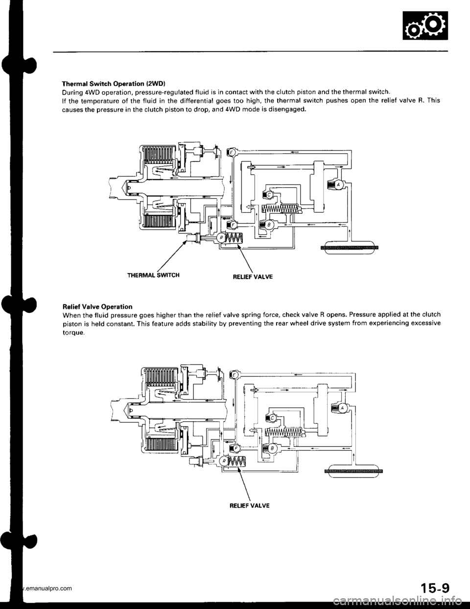
During 4WD operation, pressure-regulated fluid is in contact with the clutch piston and the thermal switch.
lf the temperature of the fluid in the differential goes too high, the thermal switch pushes open the relief valve R. This
causes the pressure in the clutch piston to drop, and 4WD mode is disengaged.
THERMAL SWITCHRELIEF VALVE
Reliet Valve Operation
When the fluid pressure goes higher than the relief valve spring force, check valve R opens. Pressure applied at the clutch
piston is held constant. This feature adds stability by preventing the rear wheel drive system from experiencing excessive
to rque.
RELIEF VALVE
15-9
www.emanualpro.com
Page 847 of 1395
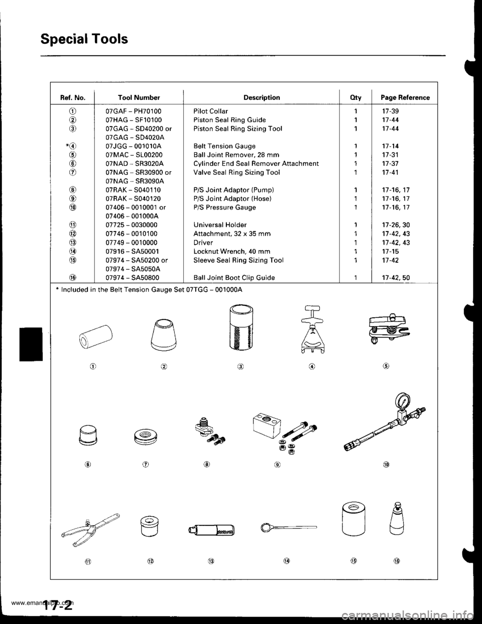
Ret. No, I Tool NumbelDescriptionfty Page Reference
o
o
-@
€r
o
@rol
@
o
@
@(}
@
@
07GAF - PH70100
07HAG - SF10100
07GAG - SD40200 or
OTGAG - SD4O2OA
07JGG - 001010A
07MAC - S100200
OTNAD _ SR3O2OA
07NAG SR30900 or
07NAG , SR3OgOA
07RAK - 50401 10
07RAK - 5040120
07406 - 0010001 or
07406 - 0010004
07725 - 0030000
07746 - 0010100
07749 - 0010000
07916 - SA50001
07974 - SA50200 or
07974 - SA5050A
07974 - SA50800
Pilot Collar
Piston Seal Ring Guide
Piston Seal Ring Sizing Tool
Belt Tension Gauge
Ball Joint Remover,23 mm
Cylinder End Seal Remover Attachment
Valve Seal Ring Sizing Tool
P/S Joint Adaptor (Pump)
P/S Joint Adaptor (Hose)
P/S Pressure Gauge
Universal Holder
Attachment, 32 x 35 mm
Driver
Locknut Wrench, 40 mm
Sleeve Seal Ring Sizing Tool
Ball Joint Boot Clip Guide
'l
1
1
1
1
1
1
1
1
1
1
1
1,l
1
1
11-39
17-44
11-44
17 -14't]-31
17 -37't7 -4'l
17-'t6, 17
17-16, 17
11-16, 17
17-26,30't]-42, 43't1-42, 43
11-15't]-42
11-42, 50
* Included in the Belt Tension Gauge Set 07TGG - 001000,4
o@
\J
,/:\
I
o
,€l-
=tt
@@
aA)
l:I/\L----.--.--------_
@o(D(9@@
17-2
www.emanualpro.com
Page 882 of 1395
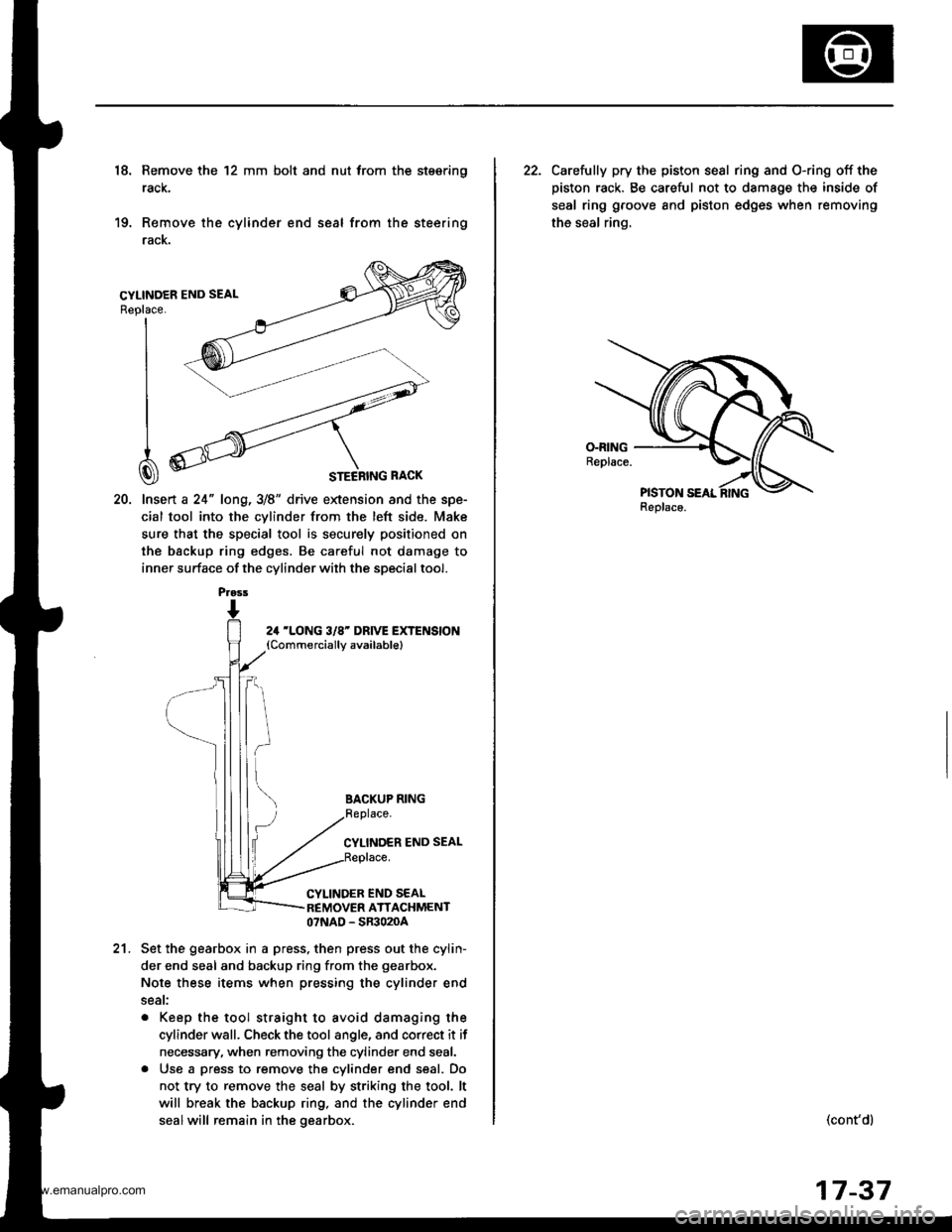
18. Remove the 12 mm bolt and nut trom the stsering
rack,
19. Remove the cylinder end seal from the steering
racK.
20. lnsert a 24" long,3/8" drive extension and the spe-
cial tool into the cvlinder from the left side. Make
sure that the special tool is securely positioned on
the backup ring edges. Be careful not damage to
inner surface of the cylinder with the special tool.
Replace.
I
I
I
CI
24 'LONG 3/8' DRIVE EXTENSION(Commerciallv available)
BACKUP RING
CYLINDER END SEAL
CYLINDER END SEALREMOVER ATTACHMENT07NAD - SR3020A
21.Set the gearbox in a press, then press out the cylin-
der end seal and backup ring from the gearbox.
Note these items when pressing the cylinder end
seat:
. Keep the tool straight to avoid damaging the
cylinder wall. Check the tool angle, and correct it if
necessary, when removing the cylinder end seal.
. Use a press to remove the cylinder end seal. Do
not try to remove the seal by striking the tool. lt
will break the backup ring, and the cylinder end
sealwill remain in the gearbox.
Prass
22. Carelully pry the piston sesl ring and O-ring off the
piston rack. Be careful not to damage the inside of
seal ring groove and piston edges when removing
the seal ring.
Replaco.
(cont'dl
17-37
www.emanualpro.com
Page 885 of 1395
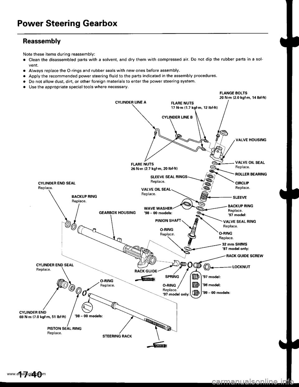
Power Steering Gearbox
Reassembly
Note these items during reassembly
. Clean the disassembled parts with a solvent, and dry them with compressed air. Do not dip the rubber parts in a sol-
vent.
. Always replace the O-rings and rubber seals with new ones before assembly.
. Apply the recommended power steering fluid to the parts indicated in the assembly procedures.
. Do not allow dust. dirt, or other toreign materials to enter the power steering system.
. Use the appropriate specialtools where necessary.
FLANGE BOLTS20 N.m (2.0 kgl.m, 14lbtftl
CYLINDER LINE AFLARE NUTS17 N.m 11.712 rbl.ftl
VALVE HOUSING
CYLINDER END SEALReplace.
VALVE OIL SEALBeplace.
ROLLER BEARING
CIRCLIPReplace.
BA.KUP RING
\/^"
WAVE WASHERBACKUP RINGReplace.97 model:HOUSING
VALVE SEAL RINGReplace.
O.RINGReplace.
32 mm SHIMS'97 mod6l only:
RACK GUIDE SCREW
O-RINGReplace.
@---r-ocxr'rur
'97 model:
'98 model:
'99 - 0O mod6ls:'9? model only:
CYLINDER END69 N.m (7.0 kgf.m, 51 lbf.ft)'98 - (x) models:
PISTON SEAL RINGReplace.
17-40
STEERING RACK
www.emanualpro.com
Page 889 of 1395
Power Steering Gearbox
Reassembly (cont'dl
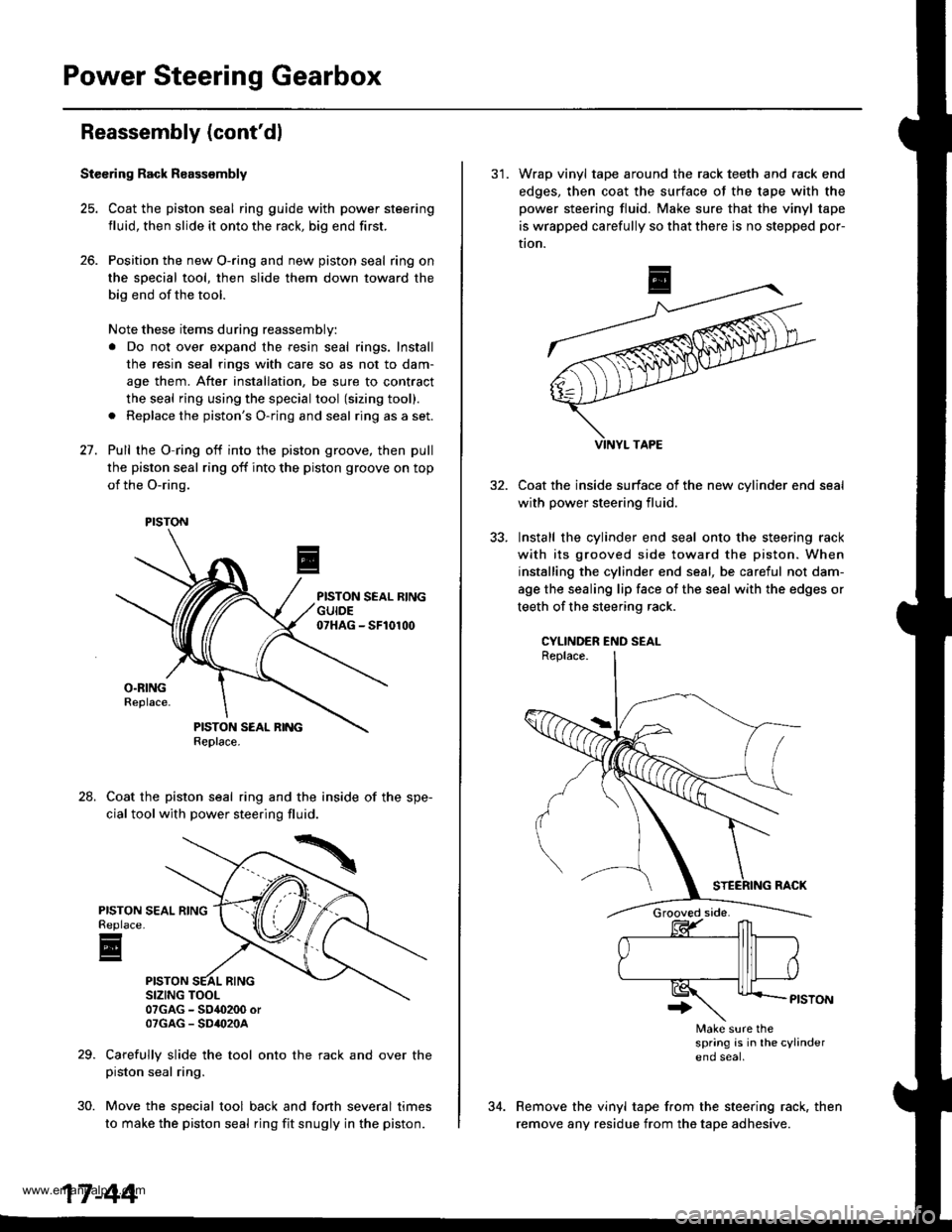
Stecring Rack R8assembly
25. Coat the piston seal ring guide with power steering
fluid, then slide it onto the rack, big end first.
26. Position the new O-ring and new piston seal ring on
the sDecial tool, then slide them down toward the
big end of the tool.
Note these items during reassembly:
a Do not over expand the resin seal rings. Install
the resin seal rings with care so as not to dam-
age them. After installation, be sure to contract
the seal ring using the special tool (sizing tool).
a Replace the piston's O-ring and seal ring as a set.
27. Pull rhe O-ring off into the piston groove, then pull
the piston seal ring off into the piston groove on top
of the O-ring.
Coat the piston seal ring and the inside of the spe-
cial tool with power steering fluid.
07GAG - SO4O200 orOTGAG - SD'()2OA
Carefully slide the tool onto the rack and over thepiston seal ring.
Move the special tool back and fonh several times
to make the piston seal ring fit snugly in the piston.
24.
PISTONReplace
E
30.
PISTON
17-44
31. Wrap vinyl tape around the rack teeth and rack end
edges, then coat the surface of the tape with the
power steering fluid. Make sure that the vinyl tape
is wrapped carefully so that there is no stepped por-
tion.
Coat the inside surface of the new cvlinder end
with power steering fluid.
Install the cylinder end seal onto the steering rack
with its grooved side toward the piston. When
installing the cylinder end seal, be careful not dam-
age the sealing lip face of the seal with the edges or
teeth of the steering rack.
CYLINDER END SEAL
Make sure thespring is in lhe cylindereno seal
Remove the vinyl tape from the steering rack, then
remove any residue from the tape adhesive.
www.emanualpro.com
Page 890 of 1395
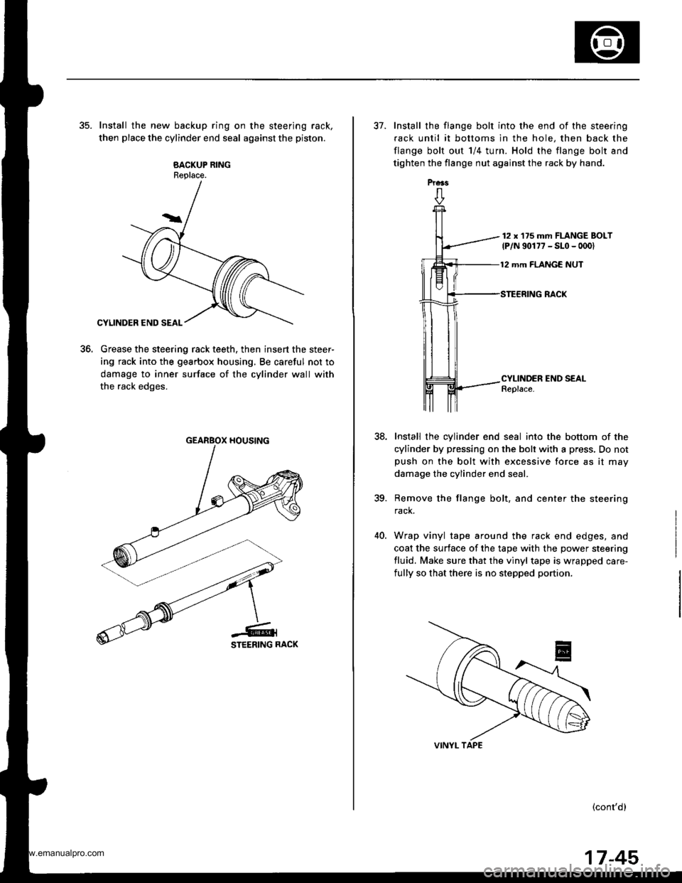
35. Install the new backup ring on the steering rack,
then place the cylinder end seal against the piston.
BACKUP RINGReplace.
Grease the steering rack teeth, then insert the steer-
ing rack into the gearbox housing, Be careful not to
damage to inner surface of the cylinder wall with
the rack edges.
to.
GEARBOX HOUSING
Prers
37. Install the flange bolt into the end of the steering
fack until it bottoms in the hole, then back the
flange bolt out 1/4 turn. Hold the flange bolt and
tighten the flange nut against the rack by hand.
12 x'175 mm FLANGE BOLT
lP/N 90177 - SLo - 0001
12 mm FLANGE NUT
38.
CYLINDER END SEALReplace.
Install the cylinder end seal into the bottom of the
cylinder by pressing on the bolt with a press, Do notpush on the bolt with excessive force as it may
damage the cylinder end seal.
Remove the flange bolt, and center the steering
rack.
Wrap vinyl tape around the rack end edges, and
coat the surface of the tape with the power steering
fluid. Make sure that the vinyl tape is wrapped care-
fully so that there is no stepped portion.
(cont'dl
ia
40.
17-45
www.emanualpro.com
Page 891 of 1395
Power Steering Gearbox
Reassembly (cont'dl
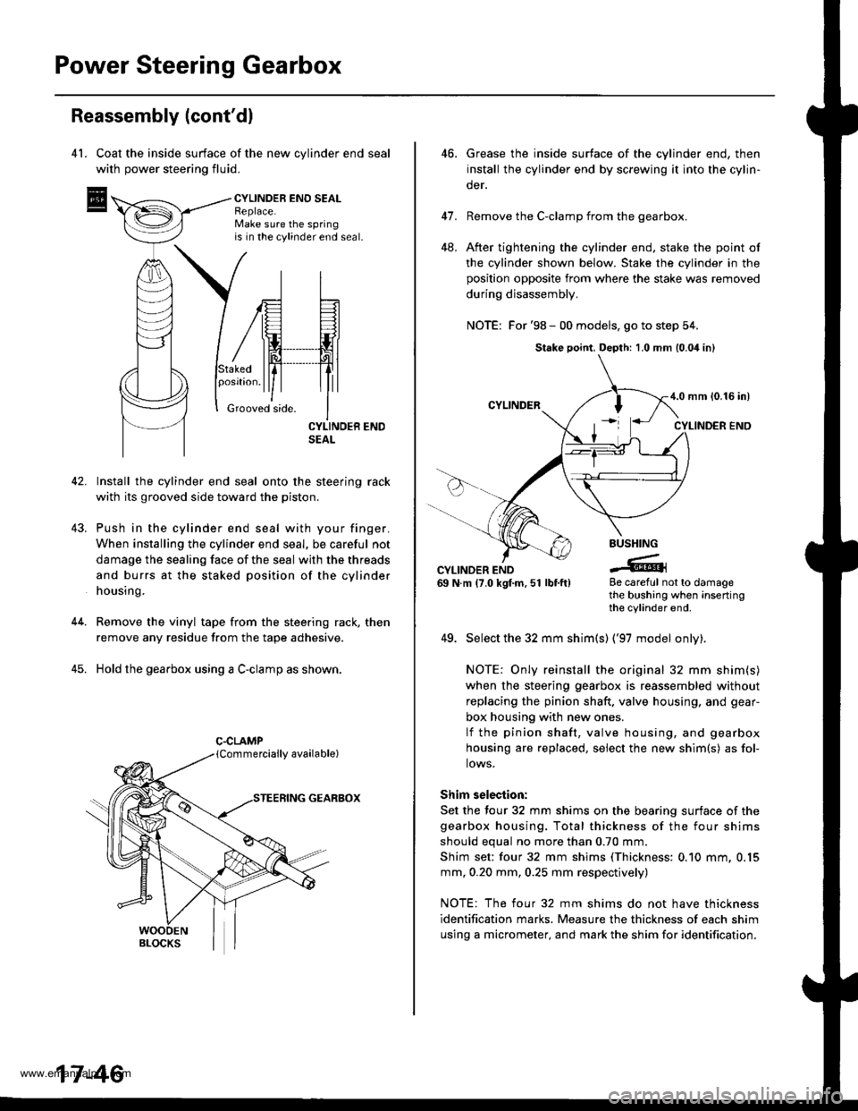
4l. Coat the inside surface of the new cvlinder end seal
with power steering fluid.
CYLINDEB ENO SEALReplace.Make sure the springis in the cylinder end seal.
43.
Stakedposrtron.
Grooved side.
42. Install the cylinder end seal onto the steering rack
with its grooved side toward the piston.
Push in the cylinder end seal with your finger.
When installing the cylinder end seal, be careful not
damage the sealing face of the seal with the threads
and burrs at the staked position of the cylinder
housing.
Remove the vinyl tape from the steering rack, then
remove any residue from the tape adhesive.
Hold the gearbox using a C-clamp as shown.
GEARBOX
44.
45.
C.CLAMP
17-46
46.Grease the inside surtace of the cylinder end, then
install the cylinder end by screwing it into the cylin-
der.
Remove the C-clamp from the gearbox.
After tightening the cylinder end, stake the point of
the cylinder shown below. Stake the cylinder in the
position opposite from where the stake was removed
during disassembly,
NOTE: For '98 - 00 models, go to step 54.
41.
48.
BUSHING
-tGCYLINDER END69 N.m (7.0 kgf.m,51 lbtft)8e careful not to damagethe bushing when insertingthe cylinder end.
49. Select the 32 mm shim(s) ('97 model onlv).
NOTE: Only reinstall the original 32 mm shim(s)
when the steering gearbox is reassembled without
replacing the pinion shaft. valve housing, and gear-
box housing with new ones.
lf the pinion shaft, valve housing, and gearbox
housing are replaced, select the new shim{s) as fol-
lows.
Shim selection:
Set the four 32 mm shims on the bearing surface of the
gearbox housing. Total thickness of the four shims
should equal no more than 0.70 mm.
Shim set: four 32 mm shims (Thickness: 0.10 mm, 0.15
mm, 0.20 mm, 0.25 mm respectively)
NOTE: The four 32 mm shims do not have thickness
identification marks. Measure the thickness of each shim
using a micrometer, and mark the shim for identification.
Stake point, Depth: 1,0 mm (0.04 inl
4.0 mm {0.16 in)
www.emanualpro.com