seat HONDA CR-V 1997 RD1-RD3 / 1.G Service Manual
[x] Cancel search | Manufacturer: HONDA, Model Year: 1997, Model line: CR-V, Model: HONDA CR-V 1997 RD1-RD3 / 1.GPages: 1395, PDF Size: 35.62 MB
Page 780 of 1395
Transmission
Cooler Flushing
@@ To prevent in;ury to face and eyos, atwayswear safety glasses ot a face shield when using thetlansmission flusher.
This procedure should be performed before reinstallingthe transmission.
2.
LCheck equipment for wear and cracks before using.Replace any worn or cracked components.
Using the measuring cup. fill the tank with 21 ounces{approximately 213 lull) ol biodegradable flushingfluid (J35944 - 20). Do not substitute with any otherfluid. Follow the handling procedure on the fluidcontaaner.
Secure the flusher filler cap, and pressurize theflusher with compressed air to 550 - 829 kpa (5.6 _
8.45 kgf/cm,, 80 - 120psi). The air line should beequipped with a water trap to ensure a dry air sys-tem.
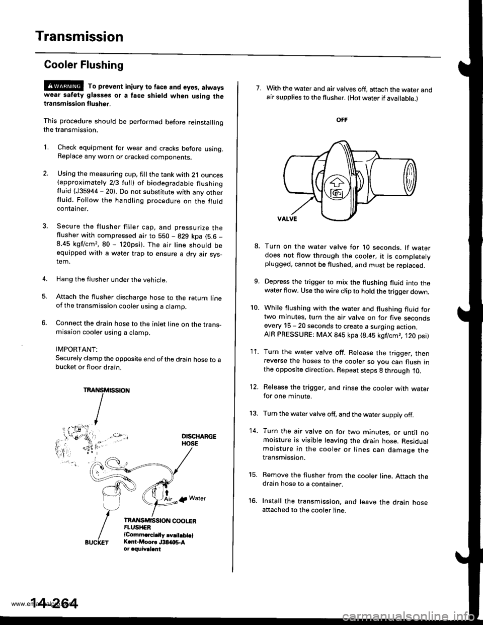
Hang the flusher under the vehicle.
Attach the flusher discharge hose to the return lineof the transmission cooler using a clamp.
Connect the drain hose to the inlet line on the trans-mission cooler using a clamp.
IMPORTANT:
Securely clamp the opposite end ofthe drain hose to abucket or floor drain.
DISCHARGEHOSE
tAirlp Water
TnAI{SrfiSStoN coot"€RFLUSHER{Comm.rcidly.v.il.bt.lK.r -Moor. J38,t{15.Aor aquival.nt
5.
14-264
7. With the water and air valves off, attach the water andair supplies to the flusher. (Hot water if available.)
10.
8.
1'�I.
Turn on the water valve for 1O seconds. lf waterdoes not flow through the cooler, it is completelyplugged, cannot be flushed, and must be replaced.
Depress the trigger to mix the flushing fluid into thewater flow. Use the wire clip to hold the trigger down.
While flushing with the water and flushing fluid fortwo minutes, turn the air valve on for five secondsevery 15 - 20 seconds to create a surging action.AIR PRESSURE: MAX 845 kpa (8.45 kgf/cmr, t20 psi)
Turn the water valve off. Release the trigger, thenreverse the hoses to the cooler so you can flush inthe opposite direction. Repeat steps 8 through 10.
Release the trigger, and rinse the cooler with wate.for one minute.
Turn the water valve off, and the water supply off.
Turn the air valve on for two minutes, or until nomoisture is visible leaving the drain hose. Residualmoisture in the cooler or lines can damage thetransmission.
Remove the flusher from the cooler line. Attach thedrain hose to a container.
Install the transmission, and leave the drain hoseattached to the cooler line.
12.
13.
14.
to.
www.emanualpro.com
Page 783 of 1395
Shift Lever
Removal/lnstallation
SRS components are located in this area. Review the
SRS component locations, precautions, and procedures
in the SRS section (24) before performing repairs or ser-
vrce.
1. Remove the instrument panel lower cover and the
column covers (see section 171.
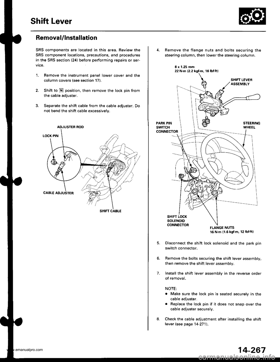
2. Shift to N position, then remove the lock pin from
the cable adjuster.
3. Separate the shift cable from the cable adjuster, Do
not bend the shift cable excessively.
ADJUSTER ROD
SHIFT CABLE
22 N.m (2.2 kgf.m, 16 lbt.ftl
7.
Remove the flange nuts and bolts securing the
steering column, then lower the steering column.
FLANGE NUTS16 N m (1.6 kgl m, 12 lbt'ftl
Disconnect the shift lock solenoid and the park pin
switch connector.
Remove the bolts securing the shift lever assembly,
then remove the shift lever assembly.
lnstall the shift lever assembly in the reverse order
of removal.
NOTE;
. Make sure the lock pin is seated securely in the
cable adjuster.
. Replace the lock pin if it does not snap over the
cable adjuster securely.
Check the cable adjustment after installing the shift
lever (see page 14-27'l).
14-267
www.emanualpro.com
Page 788 of 1395
Shift Gable
Adjustment
SRS components are located in this area. Review the SRS
component locations, precautions, and procedures in the
SRS section (241 before performing repairs or service.
1. Release the steering tilt lever.
2. Remove the access cover from the lower column
cover.
LOCK PIN
AOJUSTINGnoo
ADJUSTER
7 N.m (0.7 kg{.m,5 tbf.ft)
3. Shift to E position. then remove the lock pin from
the cable adjuster.
K\ffi
/* 1 6-,>
snenrftc YTILT LEVER IACCESS COVER
14-272
'l 1.
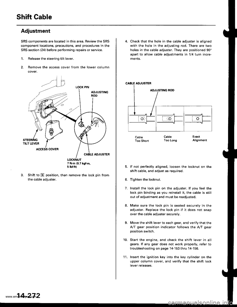
4. Check that the hole in the cable adjuster is aligned
with the hole in the adjusting rod. There are two
holes in the cable adjuster. They are positioned 90"
apart to allow cable adjustments ln l/4 turn incre-
ments.
CABLE ADJUSTER
CablsToo Short
lf not perfectly aligned, loosen the locknut on the
shitt cable. and adjust as required.
Tighten the locknut.
Install the lock pin on the adjuster. lf you feel the
lock pin binding as you reinstall it, the cable is still
out of adjustment and must be readjusted.
Make sure the lock pin is seated securely in the
adjuster. Replace the lock pin if it does not snap
over the cable adjuster securely.
Move the shift lever to each gear, and verify that the
A/T gear position indicator follows the A"/T gear
position switch.
Start the engine, and check the shift lever in all
gears. lf any gear does not work properly, refer to
troubleshooting on page 14-'153 thru 14-156.
Insert the ignition key into the key cylinder on the
upper column cover, and verify that the shift lock
tever reteases.
CableToo LongExactAlignment
7.
a
10.
www.emanualpro.com
Page 790 of 1395
Shift Gable
Replacement (cont'd)
7.
6x 1.0mm12 N.m 11.2 kgtm,8.7 tbf.ftl
Install the shift cable ln the
removat.
NOTE:
Remove the nuts securing the shift cable holder,
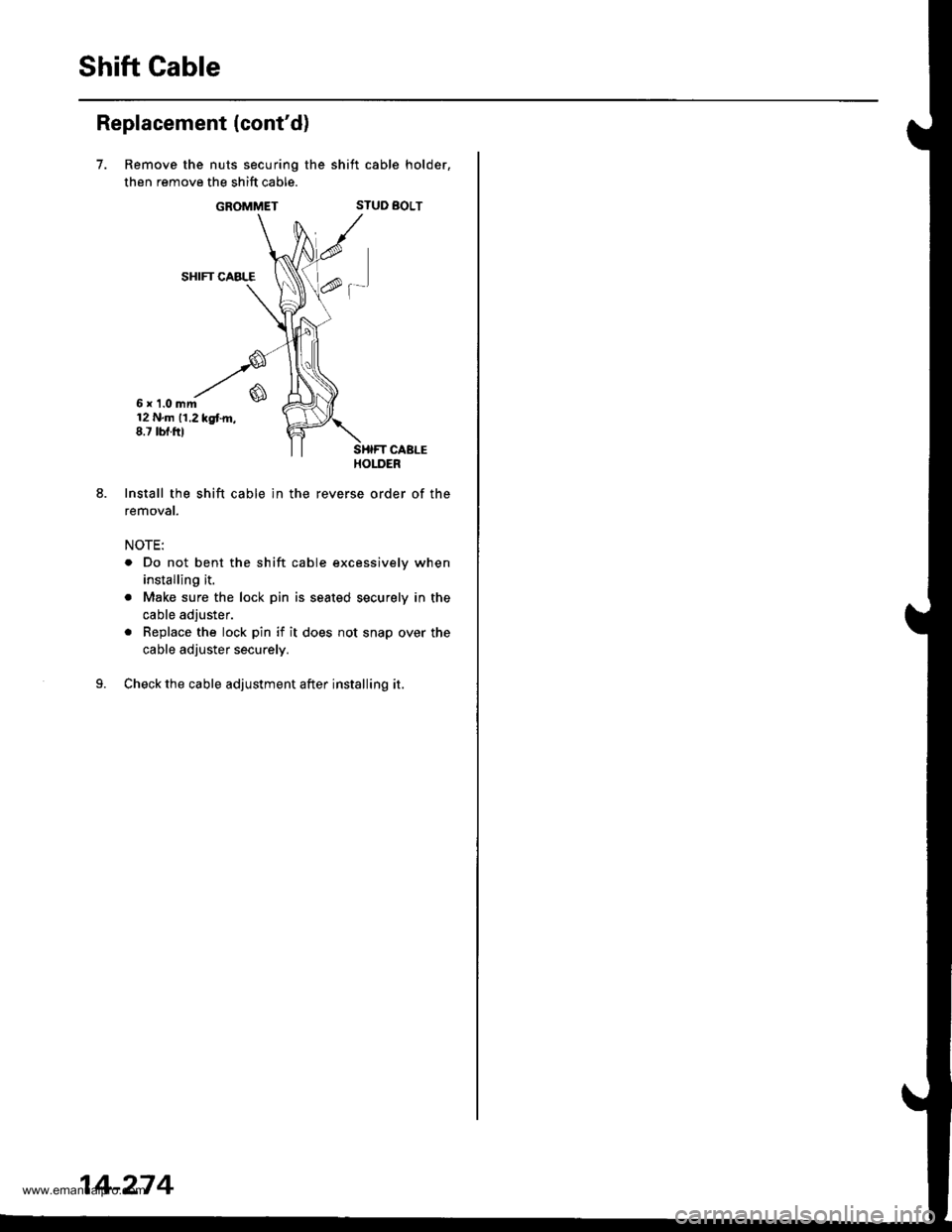
then remove the shift cable.
GROMMETSTUD BOLT
SHIFT CABLE
f-'
. Do not bent the shift cable excessively when
installing it.
. Make sure the lock pin is seated securely in the
cable adjuster.
. Replace the lock pin if it does not snap over the
cable adjuster securely.
Check the cable adjustment after installing it.
14-274
www.emanualpro.com
Page 824 of 1395
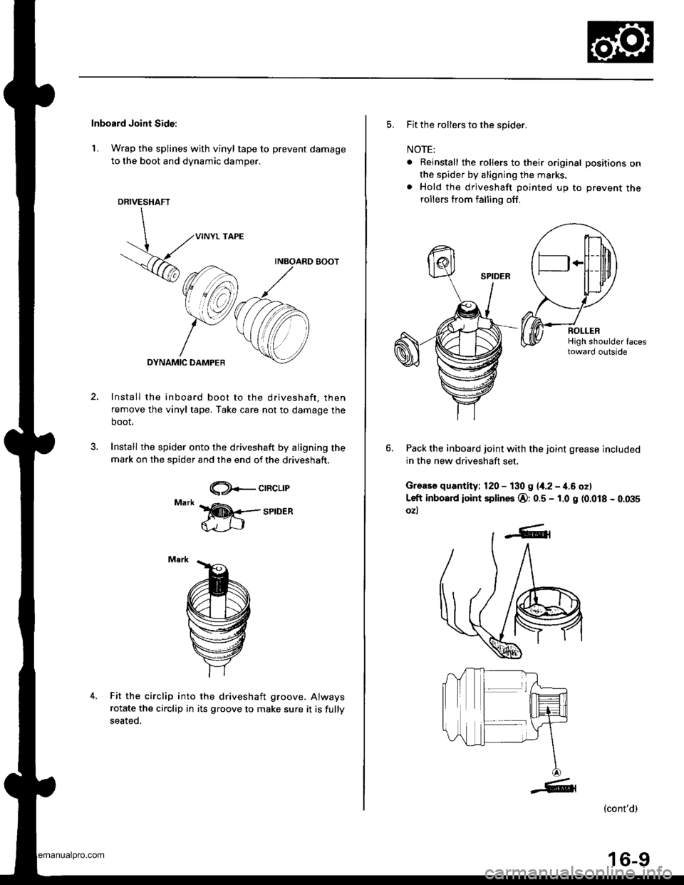
Inboard Joint Side:
1. Wrap the splines with vinyl tape to prevent damage
to the boot and dynamic damper.
DRIVESHAFT
,..',NYL rAPE
V6
uu.oa.Dsoo.�
,",^_Y,C@
Install the inboard boot to the driveshaft, then
remove the vinyl tape. Take care not to damage the
boot.
Install the spider onto the driveshaft by aligning the
mark on the spider and the end of the driveshaft.
@+-crncr-rr
4.Fit the circlip into
rotate the circlip in
seated.
the driveshaft groove. Always
its groove to make sure it is fully
5. Fit the rollers to the spider.
NOTE:
. Reinstall the rollers to their original positions onthe spider by aligning the marks.
. Hold the driveshaft pointed up to prevent therollers from falling off.
Pack the inboard joint with the joint grease included
in the new driveshaft set,
Grease quantity: 120 - 130 g {4.2 - 4.6 oz)
Left inboad ioint splines @:0.5 - 1.0 g (0.018 - 0.m5
ozl
(cont'd)
F
16-9
www.emanualpro.com
Page 825 of 1395
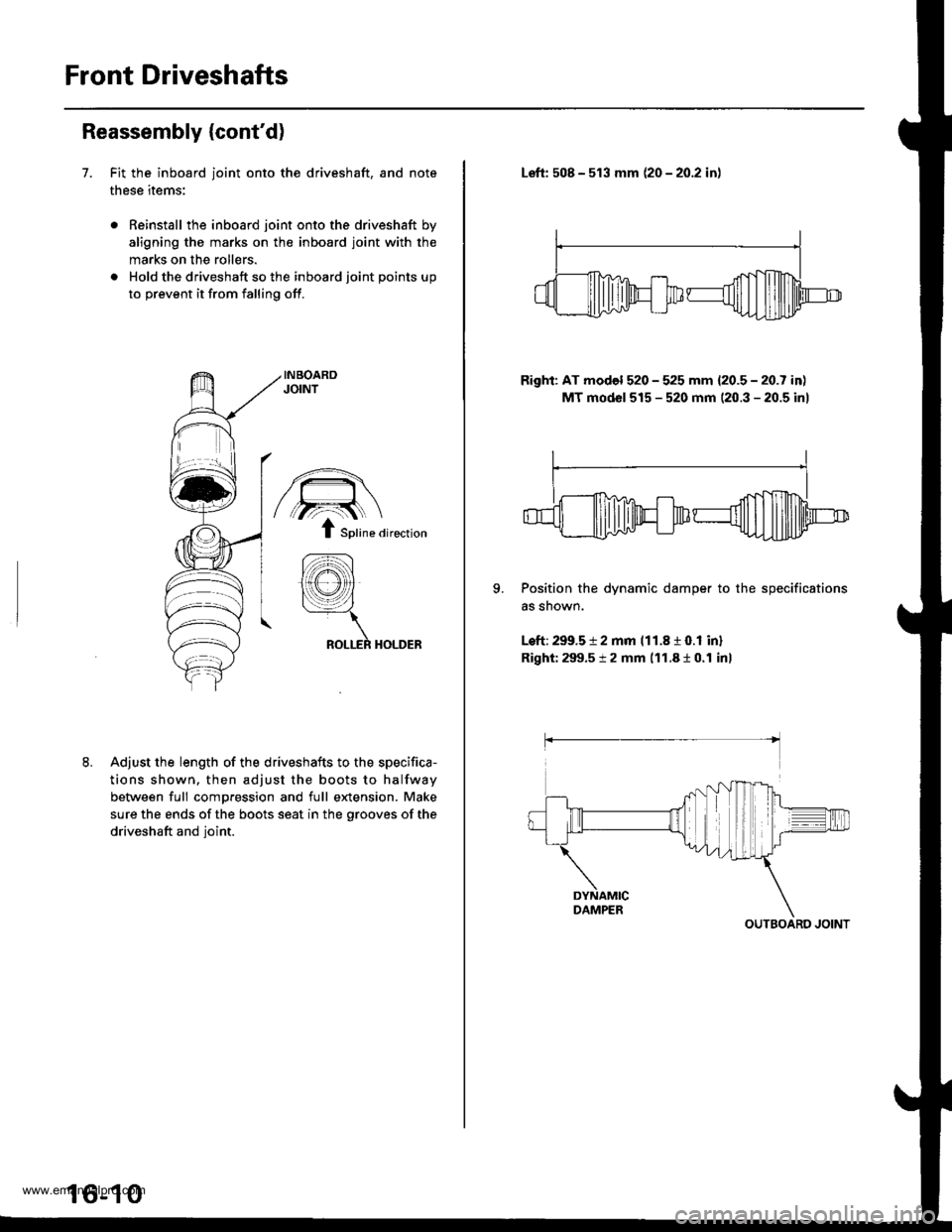
Front Driveshafts
Reassembly {cont'd)
7. Fit the inboard joint onto the driveshaft, and note
these items:
Reinstall the inboard joint onto the driveshaft by
aligning ths marks on the inboard joint with the
marks on the rollers.
Hold the driveshaft so the inboard joint points up
to prevent it from falling off.
Adjust the length of the driveshafts to the specifica-
tions shown. then adjust the boots to halfway
between full compression and full e)dension. Make
sure the ends of the boots seat in the grooves of the
driveshaft and Ioint.
/€\
/,?:..�{ \
t Sptine airection
lffi
tYl:\
ROLLER HOLDER
16-10
Left: 508 - 513 mm 120 - 2O.2 inl
Right: AT model 520 - 525 mm {20.5 - 20.7 in)
MT mod6l 515 - 520 mm (20.3 - 20.5 inl
II
-flm+dm@
9. Position the dynamic damper to the specifications
as snown.
Left: 299.5 t 2 mm 111.8 r O.l inl
Right: 299.5 t 2 mm 111.810.1 inl
OUTBOARO JOINT
www.emanualpro.com
Page 828 of 1395
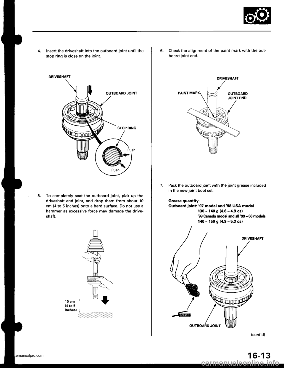
4. lnsert the driveshaft into the outboard ioint until the
stop ring is close on the joint.
DRIVESHAFT
To completely seat the outboard joint, pick up the
driveshaft and joint. and drop them from about 10
cm (4 to 5 inches) onto a hard surface, Do not use a
hammer as excessive force may damage the drive-
shaft.
i/,,,t| :l,r;;:,:.'i,,1;'/l
6. Check the alignment of the paint mark with the out-
board joint end.
DRIVESHAFT
1.Pack the outboard joint with the joint grease included
in the new joint boot set.
Grease quantity:
Outboard ioini: '97 model and '98 USA model
130 - 140 g {,1.6 - ,0.9 oz}'98 C8n8d8 modsl 8nd all '99 - 00 models
ll0 - tso g {i1.9 - 5.3 ozl
DRIVESHAFT
(cont'd)
16-13
www.emanualpro.com
Page 833 of 1395
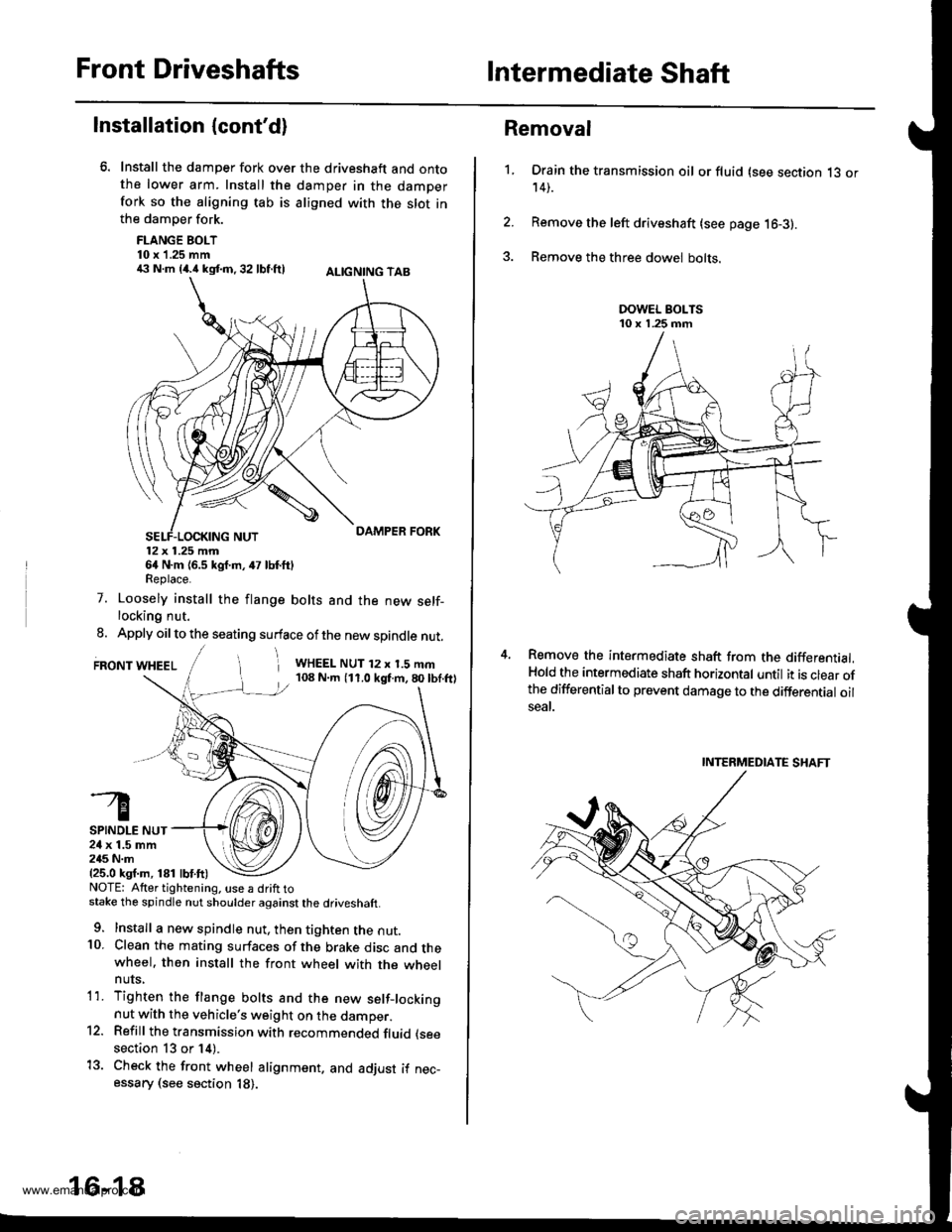
Front DriveshaftsIntermediate Shaft
Installation {cont'd}
Install the damper fork over the driveshaft and ontothe lower arm. Install the damper in the damperfork so the aligning tab is aligned with the slot inthe damper fork.
FLANGE BOLT10 x 1.25 mm€ N.m {4.i1kst.n,32 lbf.ftl ALtcNtNG TAB
12x 1.25 mm64 N.m {6.5 kgf.m, 47 lbf.ftlReplace.
7. Loosely install the flange bolts and the new self-locking nut.
8. Apply oil to the seating surface of the new spindle nut.
FRONT WHEELi WHEEL NUT 12 x 1.5 mm108 N.m (11.0 kgf.m,80lbf.ftl
SPINDLE NUT24 x 1.5 mm245 N.m{25.0 ksf.m, 181 lbf.ft)NOTE: Atter tightening. use a drift tostake the spindle nut shoulder against the driveshaft.
9. Install a new spindle nut, then tighten the nut.10. Clean the mating surfaces of the brake disc and thewheel. then install the front wheel with the wheelnuts,
1'1. Tighten the flange bolts and the new setf-lockingnut with the vehicle's weight on the damper.12. Refill the transmission with recommended fluid (see
section 13 or 14).
13. Check the front wheel alignment. and adjust if nec-essary (see section 18).
16-18
1.
Removal
Drain the transmission oil or fluid (see section 13 or14).
Remove the left driveshaft (see page 16-3).
Remove the three dowel bolts.
Remove the intermediate shaft from the differential.Hold the intermediate shaft horizontal until it is clear ofthe differentialto prevent damage to the differential oilseal.
INTERMEDIATE SHAFT
www.emanualpro.com
Page 835 of 1395
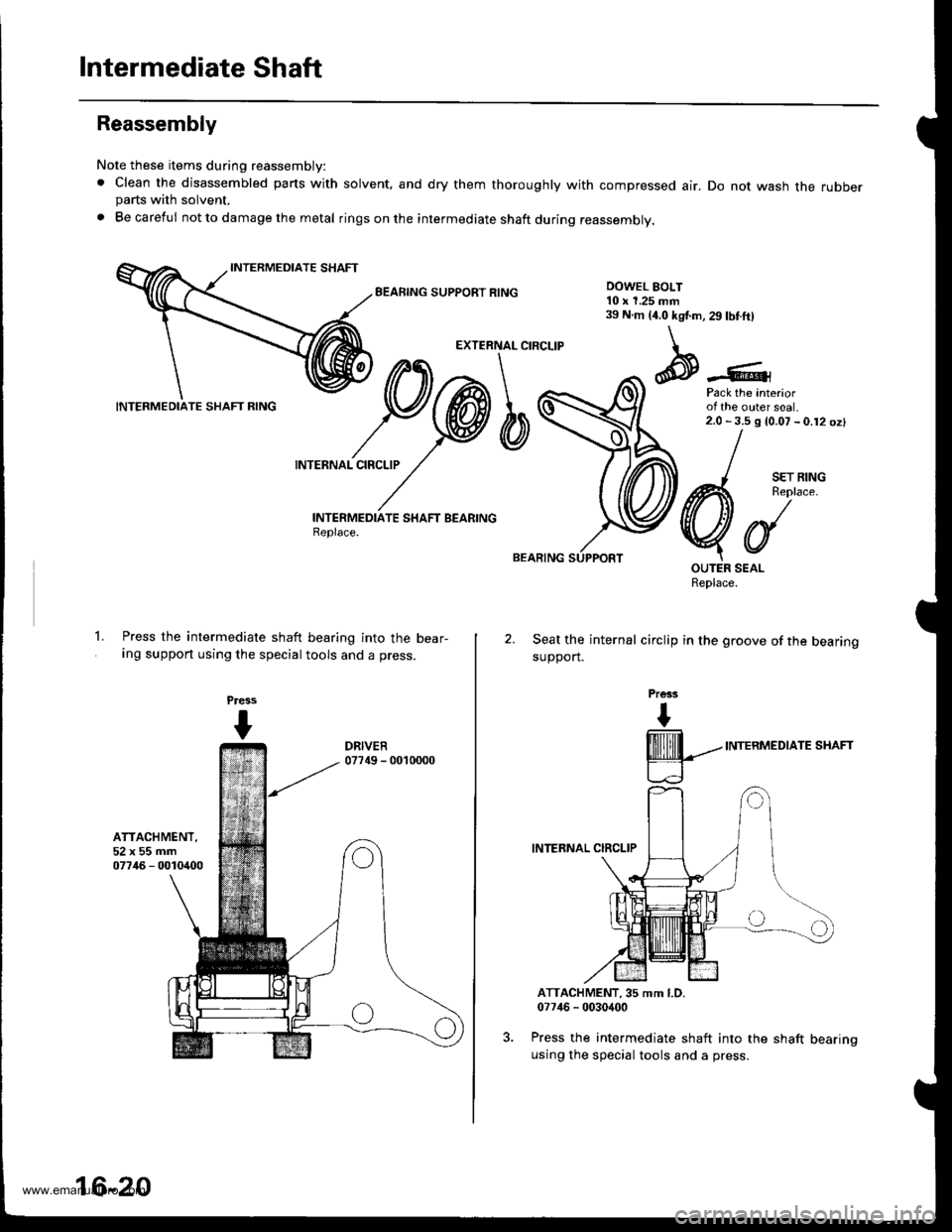
Intermediate Shaft
Reassembly
Note these items during reassembly:
. Clean the disassembled parts withparts with solvent.
. Be careful not to damage the metal
solvent, and dry them thoroughly with compressed
rings on the intermediate shaft during reassembly.
air. Do not wash the rubber
BEARING SUPPORT RING
INTERNAL CIRCLIP
Press the intermediate shaft bearing into the bear-ing support using the special tools and a press.
EXTERNAL CIRCLIP
DOWEL EOLT10 x 1.25 mm39 N.m 14.0 kg't m, 29lbf.ft)
Press
I
W--
L!
Pack the interiorof the outer seal.2.0 -3.5 g {0.07 -0.r2 oz}
'L
BEARING SUPPORTOUTER SEA-Replace.
Seat the internal circlip in the groove of the bearingsupport.
INTERMEDIATE SHAFT
ATTACHMENT.35 mm l.D.07746 - 0030400
Press the intermediate shaft into the shaft
using the special tools and a press.
ATTACHMENT,52x55mm07746 - 0010400
INTERMEDIATE SHAFT RING
Prcss
t
16-20
bearing
www.emanualpro.com
Page 836 of 1395
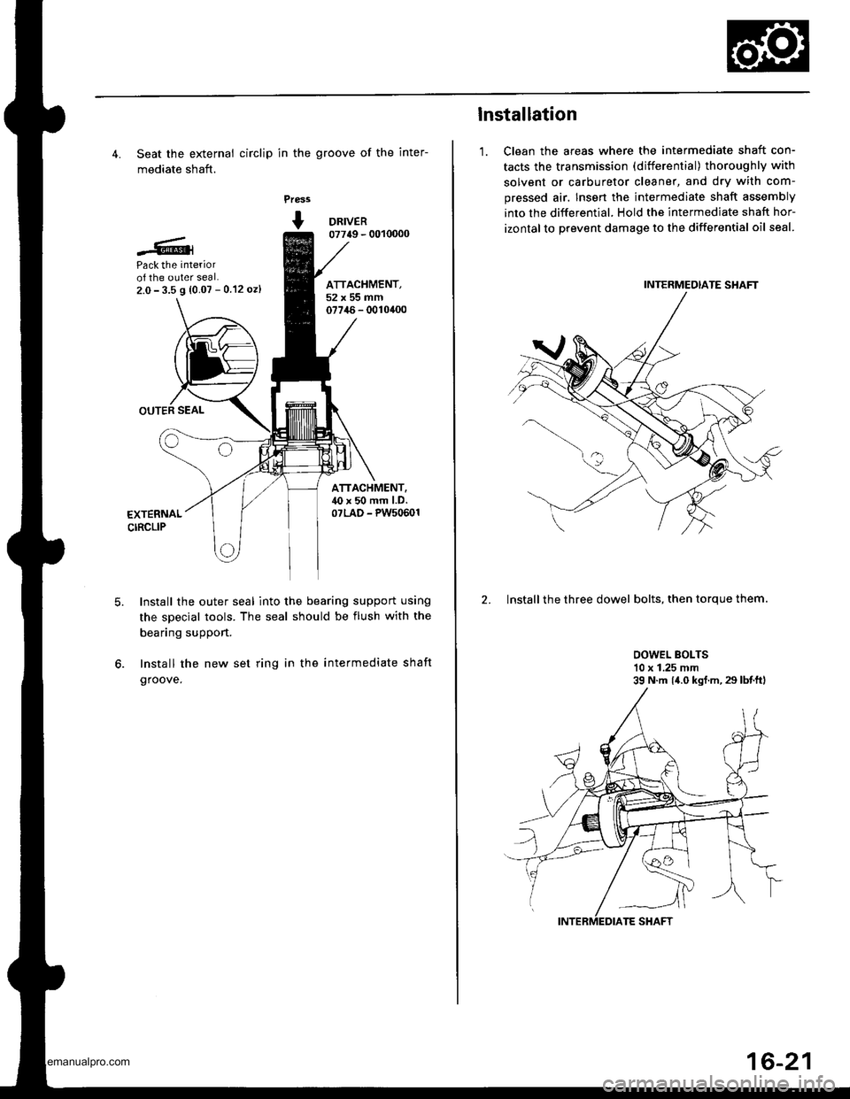
4. Seat the external circlip in the groove of the inter-
mediate shaft.
Press
+ DRNER07749 - 0010000
Pack the interiorof the outer seal.2.0- 3.5 9 {0.07 - 0.12 oz)
OUTER SEAL
ATTACHMENT,52x55mm07746- 0010400
ATTACHMENT.40 x 50 mm l.D.07LAD - PW50601EXTERNALCIRCLIP
6.
Install the outer seal into the bearing support using
the special tools. The seal should be flush with the
bearing support.
Install the new set ring in the intermediate shaft
groove.
lnstallation
1. Clean the areas where the intermediate shaft con-
tacts the transmission (differential) thoroughly with
solvent or carburetor cleaner, and dry with com-
pressed air. Insen the intermediate shaft assembly
into the differential. Hold the intermediate shaft hor-
izontal to prevent damage to the differential oil seal.
2. Install the three dowel bolts, then torque them.
OOWEL BOLTS10 x 1.25 mm39 N.m {4.0 kgf.m, 29 lbtftl
INTERMEOIATE SHAFT
16-21
www.emanualpro.com