seat HONDA CR-V 1997 RD1-RD3 / 1.G Manual PDF
[x] Cancel search | Manufacturer: HONDA, Model Year: 1997, Model line: CR-V, Model: HONDA CR-V 1997 RD1-RD3 / 1.GPages: 1395, PDF Size: 35.62 MB
Page 1024 of 1395
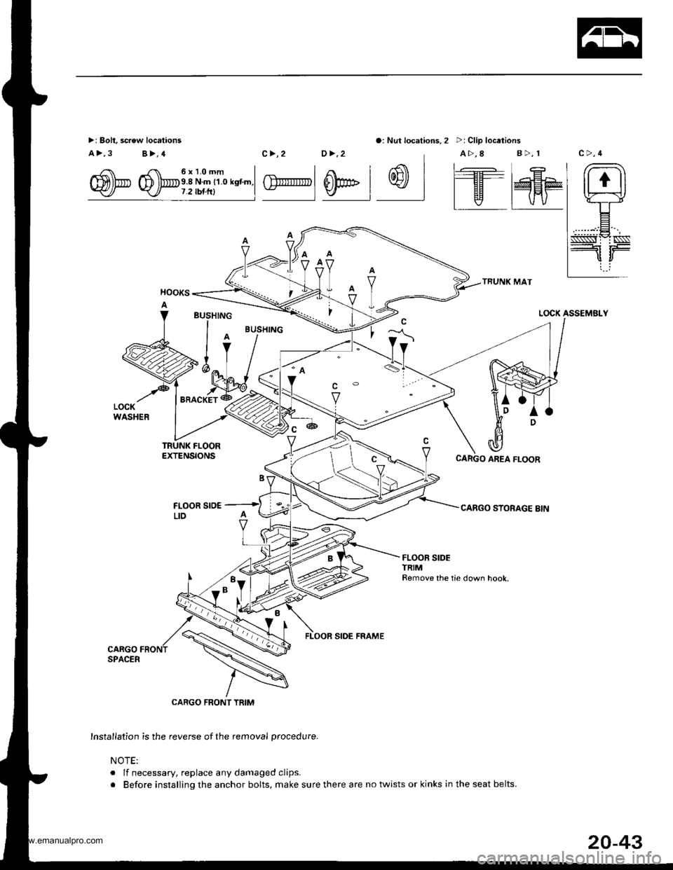
>: Bolt, screw locations
a>,3 B>,4
o: Nut locations, 2 >: Clip locations
TRUNK MAT
CARGO STORAGE BIN
/ rr. 6xl.Omm I
m)b D lbe.8 Nm r1.o ksnm.l-
c>,2 0>,2 A>,8 B>,r
| .€ | r- -I At I tl1|r' t I l���'---llH- | E
GlrrIIITTpl 0pE l w I l--Tr@HPv | | v I vv
LOCK ASSEMBLY
TRUNK FLOOREXTENSIONS
FLOOR SrO€LID
FLOOR SIDE FRAME
CARGO FRONT TRIM
Insta,lation is the reverse of the removal procedure.
NOTE:
. lf necessary, replace any damaged clips.
r Before installing the anchor bolts, make sure there are no twists or kinks in the seat belts.
BUSHING
l^IV
>ilv '%L
"ro"*i*
CARGO AREA FLOOR
l*,hl
20-43
www.emanualpro.com
Page 1025 of 1395
lnterior Trim
Headliner Removal and Installation
CAUTION: When prying with a tlat-tip screwdriver,
wrap it with protective tape to prevent damage.
NOTE:
. Take care not to bend and scratch the headliner.o Be careful not to damage the dashboard and other
interior trim.
1. Remove:
. Front and rear door side trim (see page 20-41). Front pillartrim (see page 20-41)
. Center pillar lower trim panel (see page 20-41). Center pillar upper trim (see page 20 41). Rear seat (one side, see page 20-63). Cargo area floor and cargo storage bin
{see page 20-43)
. Rear trim panel (see page 20-421
. Rear side trim panel (oneside, see page 20-42l,
. Rear hatch glass support strut (one side, seepage 20-78)
. Ouaner pillar trim panel {one side, see page 20-
42)
. Ceiling light, interior light and trunk light(see section 23)
. Rearview mirror (see page 20-28)
2. Remove the sunvisor and holder from each side.
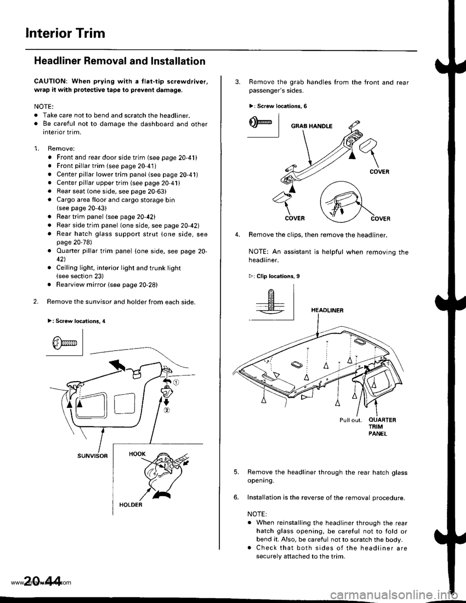
>: Scaew location3, 4
I
A\"r- |Yr* || -
suNvtsoR
20-44
3. Remove the grab handles from
passenger's sides.
>r Screw locations, 6
the front and rear
ry_l
COVER
4. Remove the clips, then remove the headliner.
NOTE: An assistant is helpful when removing the
headliner.
>: Clip locations,9
HEADLINER
Pullout. OUARTERTRIMPANEL
5. Remove the headliner through the rear hatch glass
openrng.
6. Installation is the reverse of the removal procedure.
NOTE:
. When reinstalling the headliner through the rear
hatch glass opening, be careful not to fold or
bend it, Also, be careful not to scratch the body.. Check that both sides of the headliner are
securely attached to the trim.
www.emanualpro.com
Page 1026 of 1395
Carpet Replacement
SRS comDonents are located in this area. Review the SRS
component locations, precautions, and procedures in the
SRS section {24) before performing repairs or service.
CAUTION: Put on gloves to protect your hands.
Remove:
. Front seat (see page 20-571
. Rear seat (see page 20 63)
. Kick panel (see page 20-41)
. Center pillar lower trim panel (see page 20 41)
. Front side trim {see page 20-41)
. Lower console cover 1A,/T model, see page 20-49)
. Center console (lM/T model, see page 2o-47)
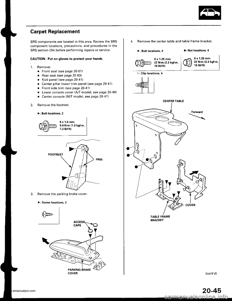
Remove the footrest.
>: Eolt locaiions,2
2.
'1.
6x1.0mm9.8 N.m {1.0 kgf.m,7 .2 tbt.ttt
FOOTREST
3. Remove the parking brake cover.
>: Screw locations,2
6bo" I"l
4. Remove the center table and table frame bracket.
>: Bolt locations, 4a: Nut locations, 4
>: Clip locations, 4
ill
,l
8 x 1.25 mm22N.m l2.2kgl.n,16 tbt ft)
8 x 1.25 mm22 N.m 12.2 kgf.m,16 tbtfrl
Forwaad
TABLE FRAMEBRACKET
{cont'd)
CENTER TABLE
COVER
20-45
www.emanualpro.com
Page 1027 of 1395
![HONDA CR-V 1997 RD1-RD3 / 1.G Manual PDF
lnterior Trim
5.
Carpet Replacement (contdl
Remove the center lower cover (M/T model).
>: Clip locations,2
lN
-ffi]
6. Remove the SRS unit covers.
>: Clip locations,2
.dL ItEu( |- qf I cARPET
FASTE HONDA CR-V 1997 RD1-RD3 / 1.G Manual PDF
lnterior Trim
5.
Carpet Replacement (contdl
Remove the center lower cover (M/T model).
>: Clip locations,2
lN
-ffi]
6. Remove the SRS unit covers.
>: Clip locations,2
.dL ItEu( |- qf I cARPET
FASTE](/img/13/5778/w960_5778-1026.png)
lnterior Trim
5.
Carpet Replacement (cont'dl
Remove the center lower cover (M/T model).
>: Clip locations,2
lN'
-ffi]
6. Remove the SRS unit covers.
>: Clip locations,2
.dL ItEu( |- qf I cARPET
FASTENER('98 - 00 models)SNS UNIT
7. '97 model: Cut areas @ and @ in the carpet, then
pullthe carpet back.'98 - 00 models: Release the fastener and cut area
@ in the carpet, then pull the carpet back.
COVER
COVER
20-46
8. Remove the clips, and release the fasteners. then
remove the carpet.
NOTE: Take care not to damage, wrinkle or twist the
carpet.
>: Clip locations.3
FASTENER
lnstallation is the reverse of the removal procedure.
NOTE:
. Take care not to damage. wrinkle or twist the
carper.
. Make sure the seat harness is routed correctly.
. lf necessary, replace any damaged clips.
. Reaftach the cut areas @ and @ ('97 model) or
cut area @ ('98 - OO models) in the carpet with
wire ties.
www.emanualpro.com
Page 1037 of 1395
Seats
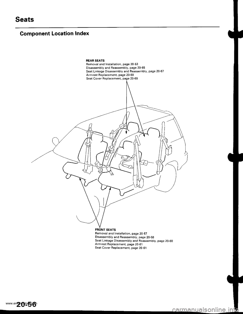
Component Location Index
REAR SEAISRemoval and lnstallation, page 20 63Disassembly and Reassembly, page 20 65Seat Linkage Disassembly and Reassembly, page 20-67Armrest Replacement, page 20-69Seat Cover Replacement, page 20-69
Removal and Installation, page 20 57Disassembly and Reassembly, page 2O-58Seat Linkage Disassembly and Reassembly, page 20-60Armrest Fleplacement, page 20 61Seat Cover Replacernent, page 20 61
20-56
www.emanualpro.com
Page 1038 of 1395
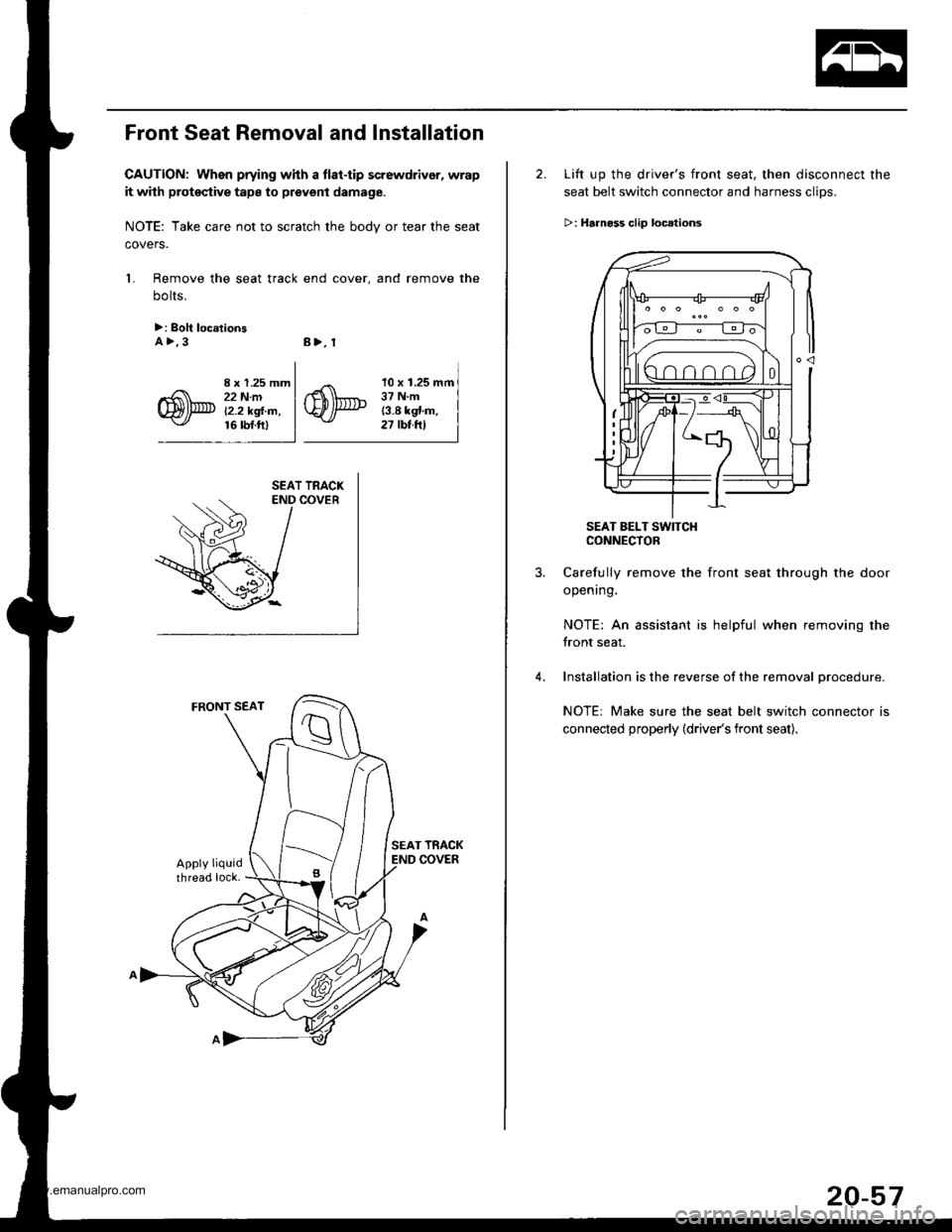
Front Seat Removal and Installation
CAUTION: When prying whh a tlat-tip screwdrivor, wrap
it with proteqtive tape to prevent damage.
NOTE: Take care not to scratch the bodv or tear the seat
covers.
1. Remove the seat track end cover, and remove the
bolts.
>: Bolt loc.tionsA>.3B>, 1
I x 1.25 mm22 N.mi'2.2 kgl.m,16 rbf.ftl
10 x 1.25 mm37 N.m13.8 kgt.m,27 tbt.ftl
2. Lift up the driver's front seat, then disconnect the
seat belt switch connector and harness clips.
>: Hrrnoss clip loc.lions
SEAT BELT SW]TCHCONNECTOR
Carefully remove the front seat through the door
opening.
NOTE: An assistant is helpful when removing the
front seat.
Installation is the reverse of the removal procedure.
NOTE: Make sure the seat belt switch connector is
connected properly (driver's front seat).
20-57
www.emanualpro.com
Page 1039 of 1395
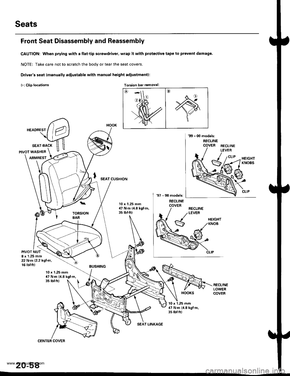
Seats
Front Seat Disassembly and Reassembly
CAUTION: When prying with a flat-tip screwdriver, wrap it with protsqtive tape to prevent damage.
NOTE: Take care not to scratch the bodv or tear the seat covers.
Driver's seat lmanually adiustable with manual height adiustmentl:
>: Clio locations Torsion bar removal:Torsion bar removal:
SEAT CUSHION
10 x 1.25 mm,17 N.m (,1.8 kgt m,35 tbt.ft)
PIVOT NUT8 x 1.25 mm22 N.n 12.2 kgl.m,16 rbI.ft)
10 x 1.25 mm47 N.m (4.8 kgf.m,35 tbtfr)
10 x 1 .25 mm47 N.m {,1.8 kgl.m.35 rbt.ft)
20-58
HOOK
HOOKS
www.emanualpro.com
Page 1040 of 1395
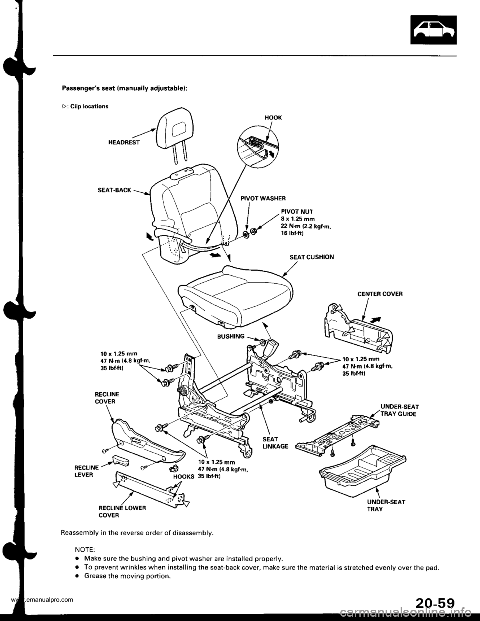
Passenger's seat (manually adiustablel:
>: Clip locations
HEADREST
SEAT.BACK
10 x 1.25 mm
PIVOT WASHER
PIVOT NUT8 x 1.25 mm22 N.m 12.2 kgl..n,16 tbt.ftl
SEAT CUSHION
CENTER COVER
BUSHING
COVER
Reassembly in the reverse order of disassembly.
NOTE:
. Make sure the bushing and pivot washer are installed properly.
. To prevent wrinkles when installing the seat-back cover, make sure the. Grease the moving portion.
'10 x 1.25 mm47 N.m {4.8 kgf m,
35 rbl.ft)
UNDER-SEATTRAY GUIDE
,U N.m 14.835 rbt.ft)
dHOOKS
10 x 1.25 mm17 N.m {4.8 kgl.m,35 tbf.ft)
HOOK
material is stretched evenly over the pad.
www.emanualpro.com
Page 1041 of 1395
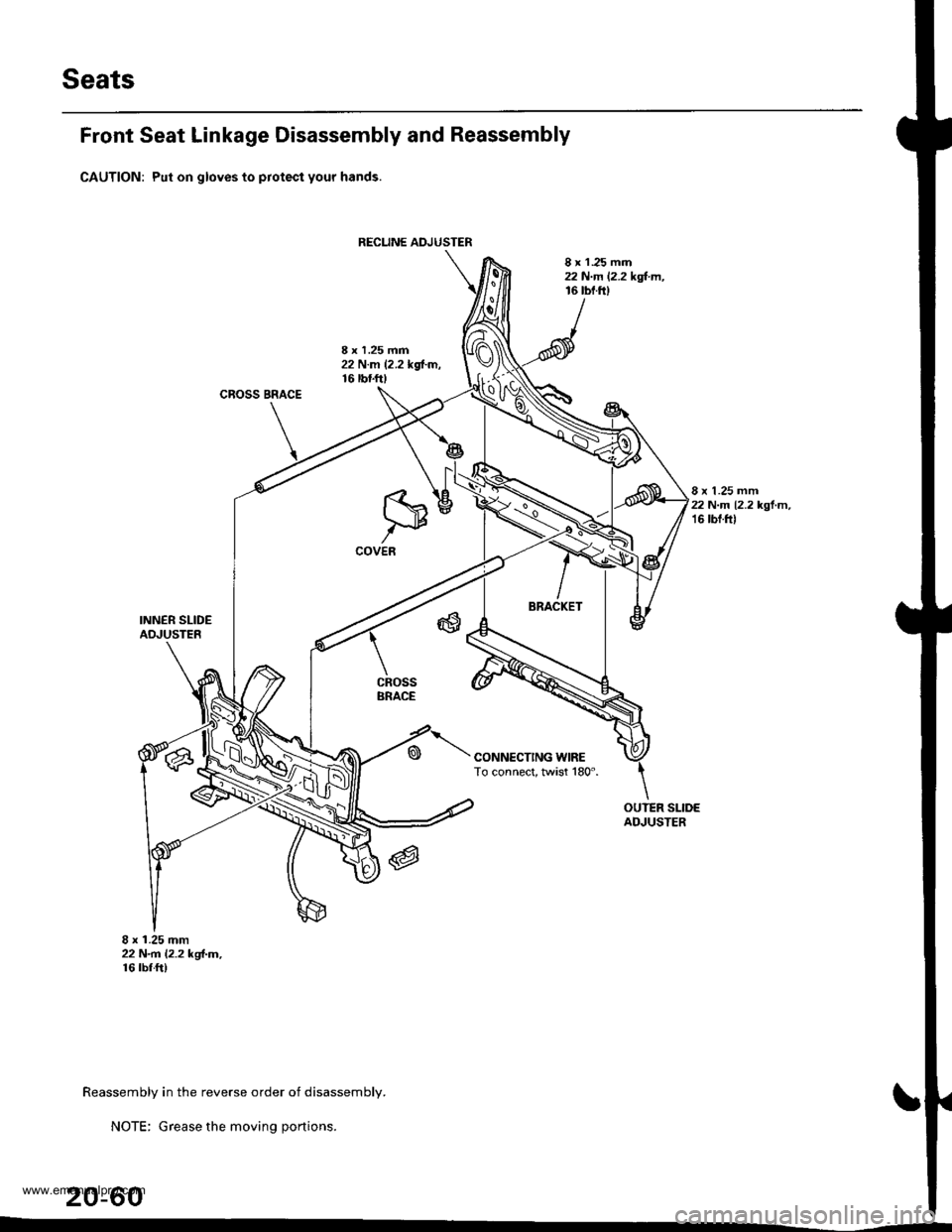
Seats
RECUNE ADJUSTER
Front Seat Linkage Disassembly and Reassembly
CAUTION: Put on gloves to protect your hands.
8 x 1 .25 mm22 N.m 12.2 kgl.m,16 tbf.fi)
8 x 1.25 mm22 N.m 12.2 kd-m,16 tbtf0
CROSS BRACE
8 x 1.25 mm22 N.m 12.2 kgl.m,16 tbf.f0
INNER SLIDEADJUSTER
8 x 1.25 mm22 N.rn l.2.2 kgl-m,16 rbr.ft)
CONNECTING WIRETo connect, twist 180".
cRossBRACE
OUTER SLIDEAOJUSTER
Reassembly in the reverse order of disassembly.
NOTE: Grease the moving portions.
20-60
www.emanualpro.com
Page 1042 of 1395
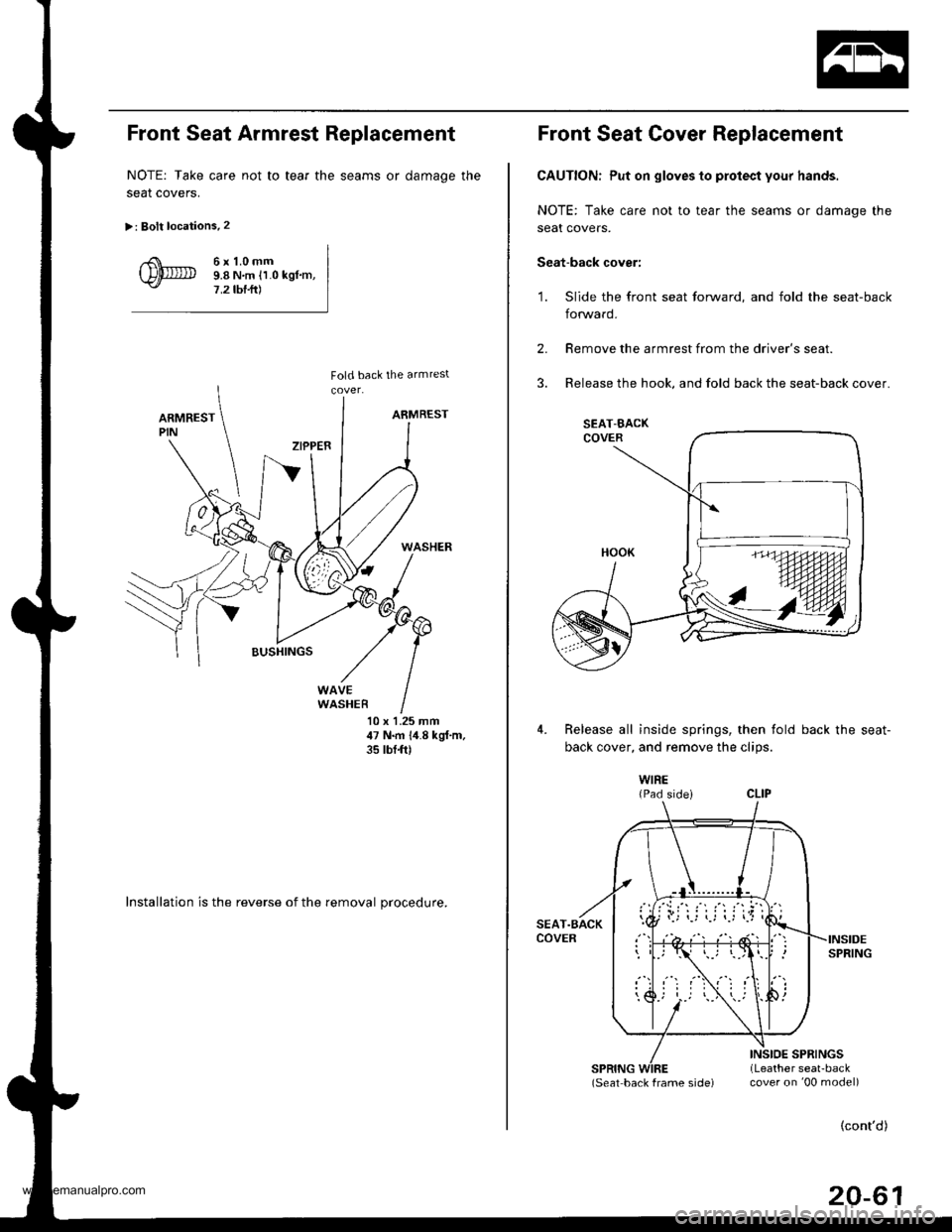
Front Seat Armrest Replacement
NOTE: Take care not to tear the seams or damage the
seat coverS.
>: Bolt locations.2
6r1.0mm9.8 N,m ll.0 kgl.m,7,2 tbf.ft)
10 x 1.25 mm47 N.m 1,1.8 kgf,m,35 tbt{t)
Installation is the reverse of the removal procedure.
Front Seat Cover Replacement
CAUTION: Put on gloves to protect your hands.
NOTE: Take care not to tear the seams or damage the
seat covers.
Seat-back cover:
'1. Slide the front seat forward, and fold the seat-back
forward.
2.
3.
Remove the armrest from the driver's seat.
Release the hook, and fold back the seat-back cover.
4.Release all inside springs, then fold back the seat-
back cover. and remove the clios.
WIRE{Pad sidei
(Seat back frame sjde) cover on '00 model)
(cont'd)
20-61
SEAT-BACK
www.emanualpro.com