seat HONDA CR-V 1997 RD1-RD3 / 1.G Owner's Guide
[x] Cancel search | Manufacturer: HONDA, Model Year: 1997, Model line: CR-V, Model: HONDA CR-V 1997 RD1-RD3 / 1.GPages: 1395, PDF Size: 35.62 MB
Page 720 of 1395
MainshaftSealing Rings
Inspection (cont'dl
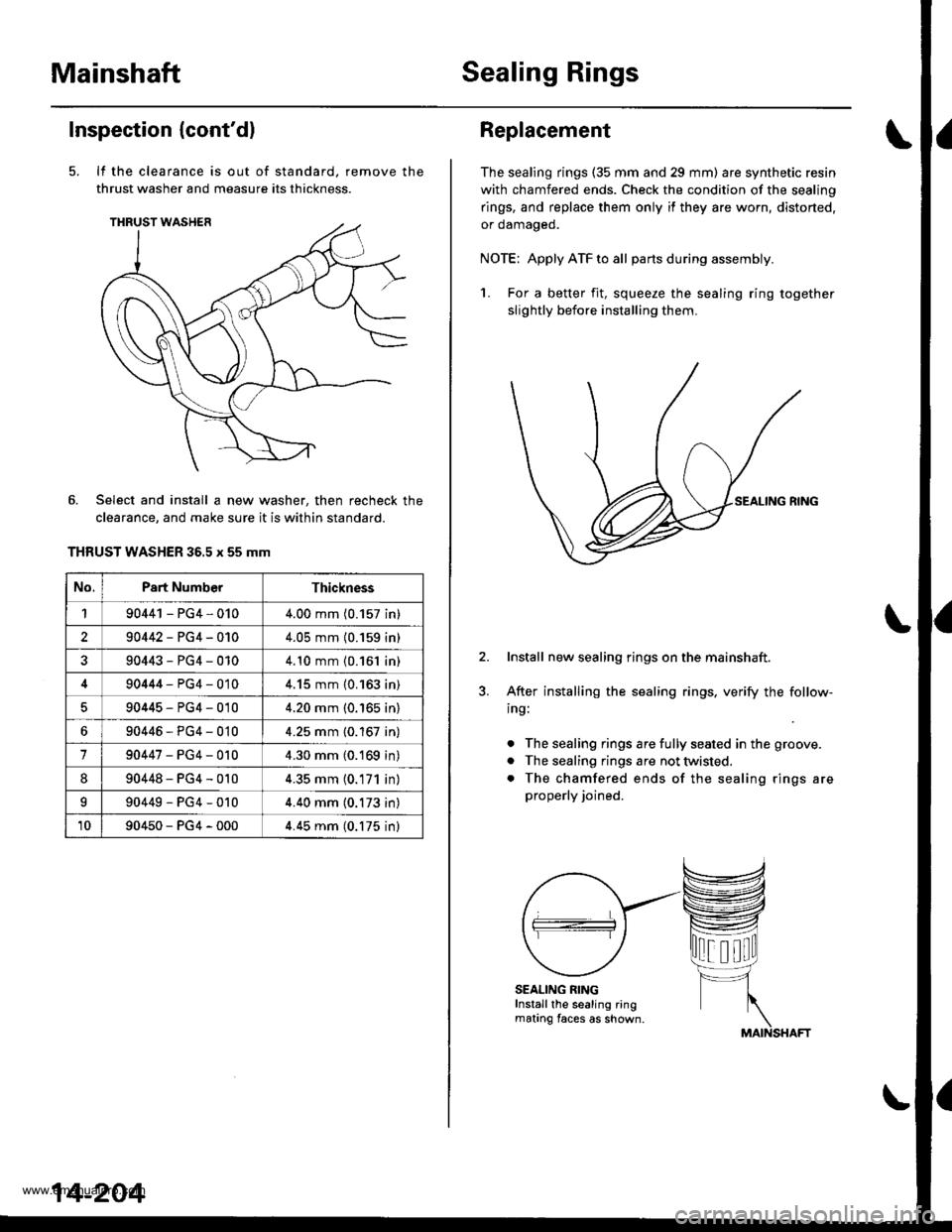
It the clearance is out of standard, remove the
thrust washer and measure its thickness.
Select and install a new washer, then recheck the
clearance, and make sure it is within standard.
THRUST WASHER 36.5 x 55 mm
No.Part NumberThickness
190441 - PG4,0104.00 mm (0.157 in)
290442-PG4-0104.05 mm (0.159 in)
90443-PG4-0104.10 mm {0.161 in)
90444-PG4-0104.15 mm {0.163 in)
90445-PG4-0104.20 mm (0.'165 in)
690446-PG4-0104.25 mm {0.167 in)
190447-PG4-0104.30 mm (0.169 in)
890448-PG4-0104.35 mm (0.171 in)
I90449-PG4-0104.40 mm (0.173 in)
1090450-PG4-0004.45 mm (0.175 inl
14-204
Replacement
The sealing rings (35 mm and 29 mm) are synthetic resin
with chamfered ends. Check the condition of the sealing
rings, and replace them only if they are worn, distorted,
or oamageo.
NOTE: Apply ATF to all partsduring assembly.
1. For a better fit, squeeze the sealing ring together
slightly before installing them.
Install new sealing rings on the mainshaft.
After installing the sealing rings, verify the follow-
ing:
. The sealing rings are fully seated in the groove.
. The sealing rings are not twisted.
. The chamfered ends of the sealing rings are
properly joined.
SEALING RINGInstall the sealing ringmating faces as shown.
www.emanualpro.com
Page 728 of 1395
Sub-shaft Bearings
Replacement
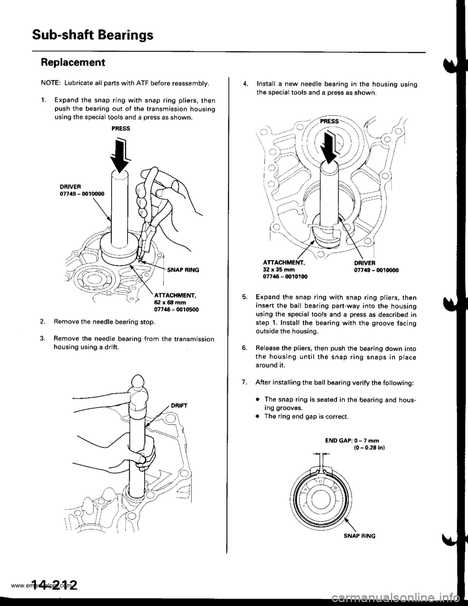
NOTE: Lubricate all parts with ATF before reassembly.
1. Expand the snap ring with snap ring pliers. thenpush the bearing out of the transmission housing
using the special tools and a press as shown.
Remove the needle bearing stop.
Remove the needle bearing from the transmission
housing using a drift.
ATTACHMENT,ai:l x 68 mm07746 - 00105q)
14-212
SNAP RING
4. Install a new needle bearing in the housing using
the sOecial tools and a oress as shown.
7.
cI
32x35mm077/46 - qt10t(x,
Expand the snap ring with snap ring pliers, then
insert the ball bearing part-way into the housing
using the special tools and a press as described in
step 1. Install the bearing with the groove facing
outside the housing.
Release the pliers, then push the bearing down into
the housing until the snap ring snaps in place
around it.
After installing the ball bearing verify the fottowing:
. The snap ring is seated in the bearing and hous-
Ing grooves.
. The ring end gap is correct.
ENDGAP:0-7mml0 - 0.28 inl
www.emanualpro.com
Page 734 of 1395
Glutch
Reassembly
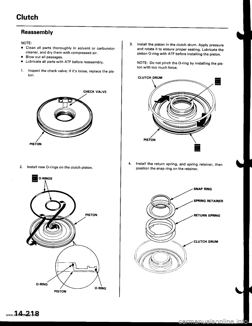
NOTE:
. Clean all parts thoroughly in solvent or carburetorcleaner, and dry them with compressed air.. Blow out all passages.
o Lubricate all parts with ATF before reassembly.
1. Inspect the check valve; if it's loose, replace the pis_ton.
CHECK VALVE
2. Install new O-rings on the clutch piston.
PtsTot{
14-218
3. Install th€ piston in the clutch drum. Apply pressure
and rotate it to ensure proper seating, Lubricate thepiston O-ring with ATF betore insta ing the piston.
NOTE: Oo not pinch the O-ring by installing the pis_ton with too much force.
CLUTCH DRUM
Install the return spring, and spring retainer, thenposition the snap ring on the retainer.
4.
SI{AP RING
SPAI'{G RETAIIIER
REIURN SPRING
CLUTCH DRUM
www.emanualpro.com
Page 742 of 1395
Differential
Side Clearance Inspection
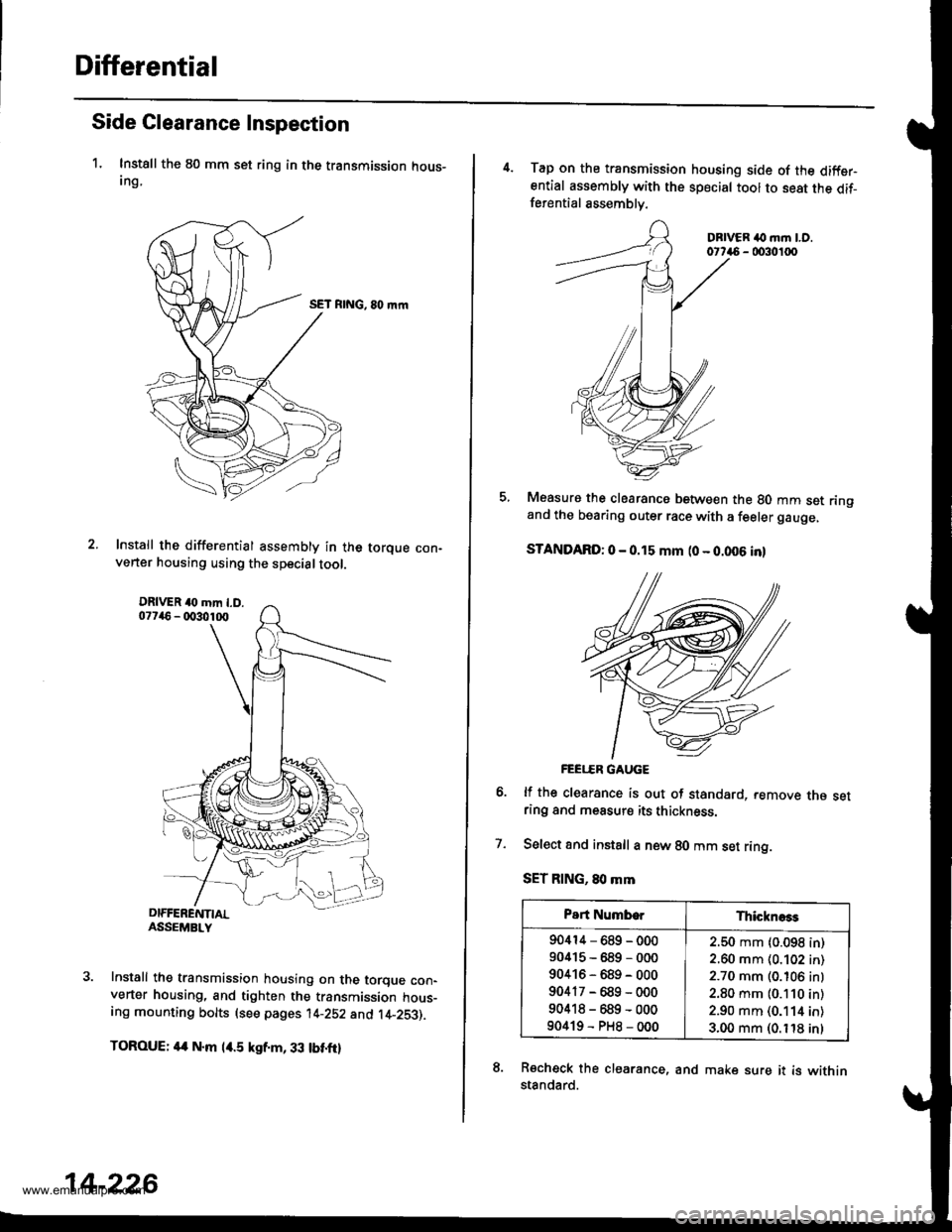
1. Instsll the 80 mm set ring in the transmission hous-Ing,
SET RING, 80 mrn
Install the differential assembly in the torque con-verter housing using the specialtool.
Install the transmission housing on the torque con-verter housing, and tighten the transmission hous-ing mounting bolts (see pages 14-252 and t4-253).
TOROUE: 4a N.m l/r.5 kgf.m, 33 tbt.ftl
14-226
4. Tap on the transmission housing side of the diffsrential assembly with the special tool to seat the dif-ferential assemblv.
DBIVER ilo m.n LO.0t746 - 0030100
Measure the clearancs between the 80 mm set ringand the bearing outer race with a feeler gauge,
STANDARD: 0 - 0.15 mm (0 - 0.006 inl
FEEI..ER GAUGE
lf the clearance is out of standard, remove rne setring and measurs its thickness.
Select and instsll a new 80 mm set ring.
SET RING, 80 mm
Recheck the clearance, and make sure it is withinstandard.
7.
Part NumborThicknoss
90414-689-000
90415-689-000
90416-689-000
90417-689-000
90418-689-000
90419-PH8-000
2.50 mm (0.098 in)
2.60 mm (0.102 in)
2.70 mm (0.106 inl
2.80 mm (0.110 in)
2.90 mm (0.114 in)
3.00 mm (0. t'18 inl
www.emanualpro.com
Page 743 of 1395
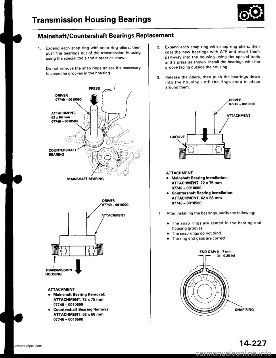
Transmission Housing Bearings
Mainshaft/Countershaft Bearings Replacement
1. Expand each snap ring with snap ring pliers, then
push the bearings out of the transmission housing
using the special tools and a press as shown.
Do not remove the snap rings unless it's necessary
to clean the grooves in the housing.
DFIVER077a9 - 001(xx)o
ATTACHMENT
ATTACHMENT
. Mainshaft Bearing Romoval:
ATTACHMENT, 72 x 75 mm
077/16 - 0010600
. Countqrshaft Bearing Removal:
ATTACHMENT, 62 x 68 mm
07746 - 0010500
MAINSHAFT BEARING
4.
Expand each snap ring with snap ring pliers, then
coat the new bearings with ATF and insert them
part-way into the housing using the special tools
and a press as shown. Install the bearings with the
groove facing outside the housing.
Release the pliers, then push the bearings down
into the housing until the rings snap in place
around them.
077/49 - 0010000
ATTACHMENT
. Mainshaft Bearing Installation:
ATTACHMENT,72 x 75 mm
07746 - 0010600
. Countershaft Bearing Instsllation:
ATTACHMENT, 52 x 68 mm
077'16 - 0010500
After installing the bearings, verify the following:
. The snap rings are seated in the bearing and
housrng grooves.
. The snap rings do not bind.
. The ring end gaps are correct,
l0 - 0.28 in)
SNAP RING
ENDGAP:0-7rnm
14-227
www.emanualpro.com
Page 744 of 1395
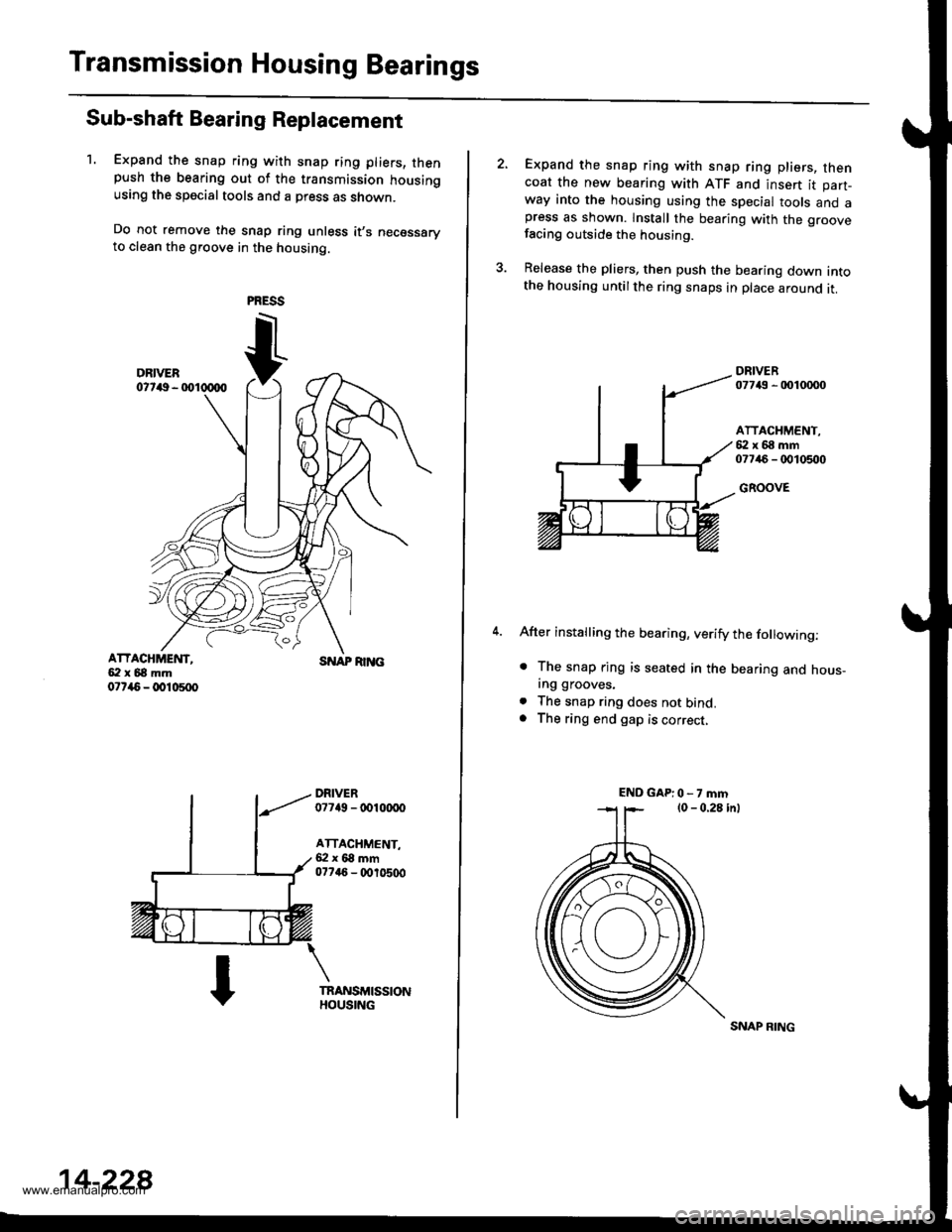
Transmission Housing Bearings
Sub-shaft Bearing Replacement
1. Expand the snap ring with snap ring pliers, thenpush the bearing out of the transmission housingusing the special tools and a press as shown.
Do not remove the snap ring unless it,s necessaryto clean the groove in the housing.
ATTACHMEI{T,5:l x 68 mm07r{5 - @10500
SNAP RI]TG
DRIVER07749 - tDl(xx)o
ATTACHMENT,6:l x 68 mm077a6 - (X,r0500
14-228
SNAP RING
Expand the snap ring with snap ring pliers, thencoat the new bearing with ATF and insert it part-way into the housing using the special tools and apress as shown. lnstall the bearing with the groovefacing outside the housing.
Release the pliers, then push the bearing down intothe housing untilthe ring snaps in place around it.
DRIVER07743 - 0010mo
ATTACHMENT,{i:l x 68 mm07746 - 0010500
GROOVE
After installing the bearing, verify the following:
. The snap rjng is seated in the bearing and hous_ing grooves.
. The snap ring does not bind.. The ring end gap is correct,
ENDGAP:0-7mm
www.emanualpro.com
Page 750 of 1395
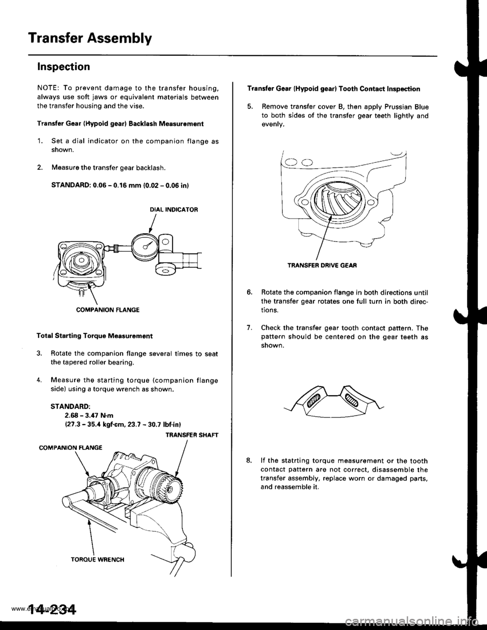
Transfer Assembly
Inspection
NOTE: To prevent damage to the transfer housing,
always use soft jaws or equivalent materials between
the transfer housing and the vise.
Trsnsfer Gear (Hypoid gear) Backl8sh M€asurem€nt
1. Set a dial indicator on the companion flange as
snown.
2. Measure the transfer gear backlash.
STANDARD: 0.06 - 0.16 mm {0.02 - 0.06 in)
Total Starting Torque Meagurgm€nt
3, Rotate the companion flange several times to seat
the tapered roller bearing.
4. Measure the starting torque (companion flange
side) using a torque wrench as shown,
STANDARD:
2.68 - 3.,17 N.m(27.3 - 35.,1 kgf.cm, 23.7 - 30.7 lbf.inl
TRANSFER SHAFT
DIAL INDICATOR
COMPANION FLANGE
14-234
Transfer Gear (Hypoid gear) Tooth Contact Inspection
5, Remove transfer cover B, then apply Prussian Blue
to both sides of the transfer gear teeth lightly and
Rotate the companion flange in both directions until
the transfer gear rotates one full turn in both direc-
tions.
Check the transfer gear tooth contact pattern. Thepattern should be centered on the gear tseth as
snown.
6.
7.
8.lf the statrting torque measurement or the tooth
contact pattern are not correct, disassemble the
transfer assembly, replace worn or damaged parts,
and reassemble it.
TRANSFER DRIVE G€AR
www.emanualpro.com
Page 759 of 1395
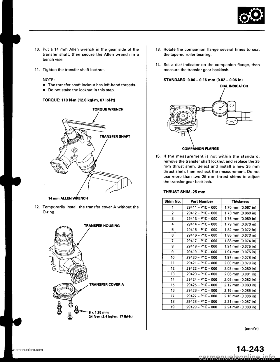
10.
11.
Put a 14 mm Allen wrench in the gear side of the
transfer shaft, then secure the Allen wrench in a
bench vise.
Tighten the transfer shaft locknut.
NOTE:
. The transfer shaft locknut has left-hand threads.
. Do not stake the locknut in this step.
TOROUE: 118 N'm 112.0 kgf.m, 87 lbf.ftl
Temporarily install the transfer cover A without
O-ring.
TRANSFER HOUSING
TRANSFER COVER A
the12.
g/FrE24 N.m 12.4 kgt.m, 17 lbf.ftl
TOROUE WRENCH
tt el
g 9-r'r.ru--g 24 N.m 12.4 |
14-243
13.
14.
Rotate the companion flange several times to seat
the tapered roller bearing.
Set a dial indicator on the companion flange, then
measure the transfer gear backlash.
STANDARD: 0.06 - 0.16 mm {0.02 - 0.06 inl
COMPANION FLANGE
lf the measurement is not within the standard.
remove the transfer shaft locknut and replace the 25
mm thrust shim. Select and install a new 25 mm
thrust shim. then recheck the measurement. Do not
use more than two 25 mm thrust shims to adiust
the transfer gear backlash.
THRUST SHIM, 25 mm
(cont'd)
15.
DIAL INOICATOR
Shim No.Part NumborThickness
I29411-P1C-0001.70 mm (0.067 in)
229412-P1C-0001.73 mm (0.068 in)
29413-P1C-0001.76 mm (0.069 in)
429414-P1C-0001.79 mm (0.070 in)
29415-PlC-0001.82 mm (0.072 in)
629416-P1C-0001.85 mm (0.073 ini
729417-PlC-0001.88 mm (0.074 in)
d29418-P1C-0001.91 mm {0.075 in)
29419-P1C-0001.94 mm (0.076 in)
1029420-PtC-0001.97 mm (0.078 in)
1129421 - P1C - 0002.00 mm (0.079 in)
29422-P1C-0002.03 mm 10.080 in)
29423-P'1C-0002.06 mm (0.081 in)
1429424-P1C-0002.09 mm 10.082 in)
29425-P1C-0002.12 mm (0.083 in)
1629426-P1C-0002.'15 mm (0.085 in)
1729427 - P1C -O002.18 mm (0.086 in)
1829428-PlC-0002.21 mm (0.087 in)
1929429-P1C-0002.24 mm {0.088 in)
www.emanualpro.com
Page 762 of 1395
Transfer Assembly
Reassembly (cont'd)
Secure the transfer housing in a bench vise with
soft jaws. To prevent damage, always use soft jaws
or equivalent materials between the transfer hous-
ing and the vise.
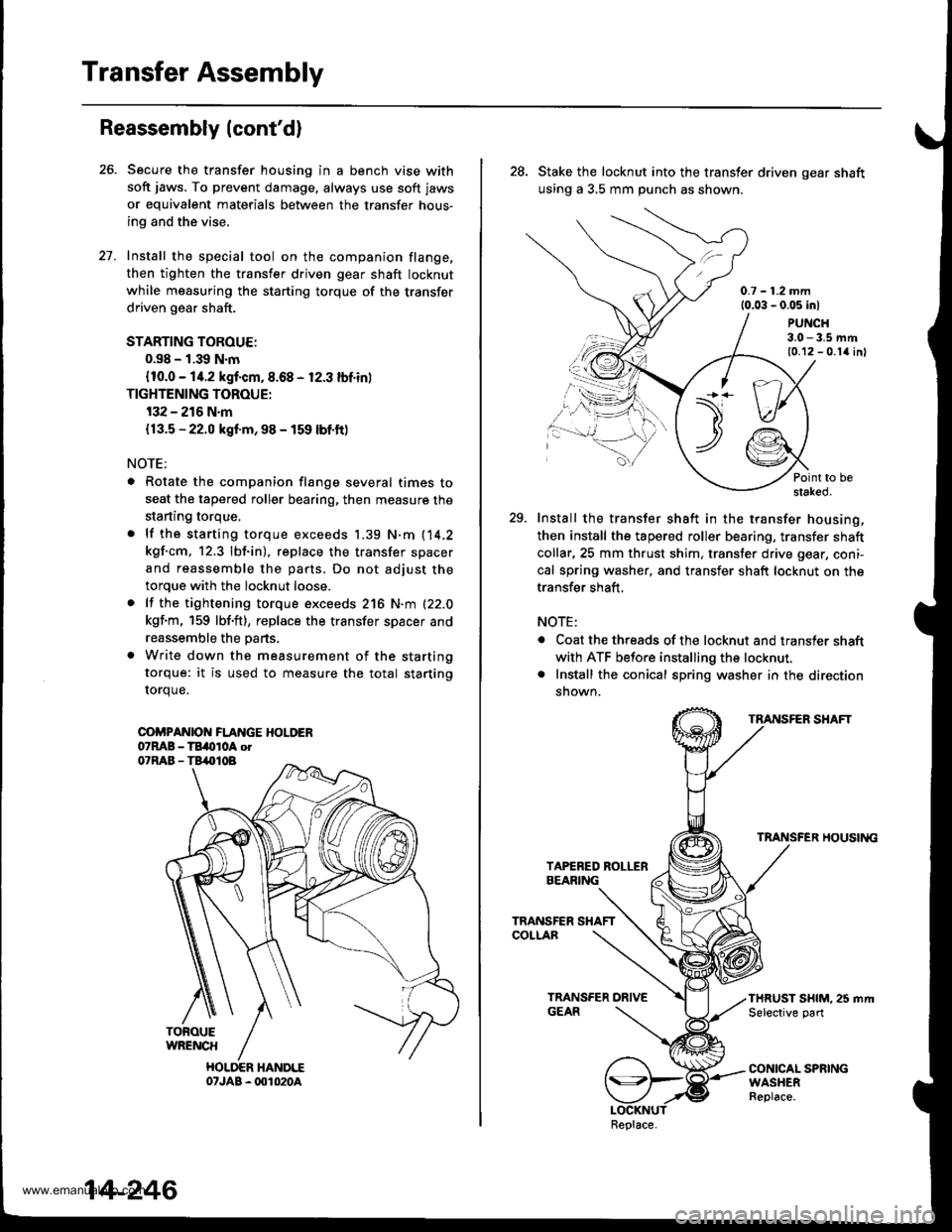
Install the special tool on the companion flange,
then tighten the transfer driven gear shaft locknut
while measuring the starting torque of the transfer
driven gear shaft.
STARTING TOROUE:
0.s8 - 1.39 N.m
{10.0 - 14.2 kgf.cm,8.68 - 12.3 lbf.in)
TIGHTENING TOROUE:
132 - 216 N.m
{13.5 - 22.0 kgf.m, 98 - 159 lbf.ft)
NOTE;
. Rotate the companion flange several times to
seat the tapered roller bearing, then measure the
starting torque,
. lf the starting torque exceeds 1.39 N.m (14,2
kgf.cm, 12.3 lbf.in), replace the transfer spacer
and reassemble the parts. Do not adjust the
torque with the locknut loose.
. lf the tightening torque exceeds 216 N.m (22.0
kgf.m, 159 lbf'ft), replace the transfer spacer and
reassemble the parts.
. Write down the measurement of the starting
torque: it is used to measure the total starting
rorque.
COi'PANIOI{ FLANGE HOLDER07MB - TBi(tloA otO'RAB - TB,.|}IOB
TOFOUEWRENCH
HOLDER HANDLE07JAB - 001020A
27.
14-246
28. Stake the locknut into the transfer driven gear shaft
using a 3,5 mm punch as shown.
0.7 - 1.2 mm{0.03 - 0.05 inl
PUNCH3.0 - 3.5 mm10.12 - 0.1{ inl
Point to bestaked.
29. Install the transfer shaft in the transfer housing,
then install the tapered roller bearing, transfer shaft
collar,25 mm thrust shim, transter drive gear, coni-
cal spring washer, and transfer shaft locknut on the
transfer shaft,
NOTE:
. Coat the threads of the locknut and transler shaft
with ATF before installing the locknut.. Install the conical spring washer in the direction
snown.
TRANSFER SHAFT
TRANSFER HOUSII{G
THRUST SHIM. 25 mrt|Selective part
CONICAL SPRINGWASHERReplace.
\t)t--/./
.,.-,.,\
Replace.
www.emanualpro.com
Page 770 of 1395
Transmission
28.
Reassembly (cont'd)
PARX GEAR
ONE.WAY CLUTCH
BEARING
Install the mainshaft speed ssnsor (with new O-ring) on the transmission housing.
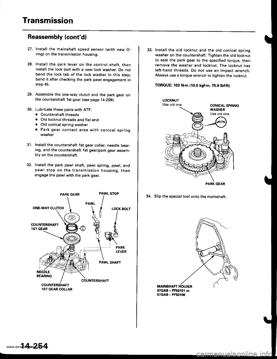
Install the park lever on the control shaft, theninstall the lock bolt with a new lock washer. Do notbend the lock tab of the lock washer in this step;bend it after checking the park pawl engagement instep 45.
Assemble the one-way clutch and the park gear onthe countershaft 1st gear (see page l4-2Og).
Lubricate these pans with ATF:. Countershaft threads. Old locknut threads and flat end. Old conical spring washer. Park gear contact area with conical springwasner
Install the countershaft 1st gear collar, needle bear-ing, and the countershaft 1st gear/park gear assem-bly on the countershaft.
Install the park pawl shaft. pawl spring, pawl. andpawl stop on the transmission housing, thenengage the pawl with th€ park gear.
31.
PAWL
I
I
a
STOP
LOCK BOLT
PAWL SHAFT
COUNIERSHAFTCOUNTERSHAFTlST GEAR COLLAR
14-254
33. Install the old locknut and the old conical springwasher on ths countershaft. Tighten the old locknutto seat the park gear to the specified torque, thenremove th€ washer and locknut. The locknut hasleft-hand threads. Do not use an impact wrench.Always use a torque wrench to tighten the locknut.
TOROUE: 103 N.m {10.5 kgf.m, 75.9 lbnft)
34. Slip the specialtool ontothe mainshaft.
MAINSHAFT07GAB - PF50101 or07GAB - PF501q)
PARK GEAR
www.emanualpro.com