fuse HONDA CR-V 1997 RD1-RD3 / 1.G Repair Manual
[x] Cancel search | Manufacturer: HONDA, Model Year: 1997, Model line: CR-V, Model: HONDA CR-V 1997 RD1-RD3 / 1.GPages: 1395, PDF Size: 35.62 MB
Page 659 of 1395

L
Input Test -'99 - 00 Models
Remove the gauge assembly from the dashboard {see section 20), and disconnect the 14P connector from the gauge
assembly (see section 23).
Inspect the connector and socket terminals to be sure they are all making good contact.
a lf the terminals are bent. loose, or corroded. repair them as necessary. and recheck the system.
. lf the terminals look OK, make the following input tests at the 14P connector.- lf a test indicates a problem, find and correct the cause, then recheck the system.- lf all the input tests prove OK, but the indicator is faulty, replace the printed circuit board.
GAUGE ASSEMBLY 14P CONNECTOR
Wire side of female terminals
CavityWire
ColorTest ConditionTest: Desired ResuhPossible Caus6
{lf resutt is not obtainod)
1YEL
lgnition switch ON (ll)Check for voltage to ground:
There should be battery voltage.
. Blown No.25 (7.5 A) fuse in the
under-dash fuse/relay box. An open in the wire
2RE D/BLK
Combination light
switch ON and dash
lights brightness con-
trol dial on full bright
Check for voltage between No. 2
and No.3 terminals:
There should be battery voltage.
Blown No. 47 {7.5 A) fuse in the
under-dash fuse/relay box
Faulty combination light switch
Faulty dash light brightness
controller
An open in the wire
5RED
BRNShift lever in ECheck for continuity to ground:
There should be continuity.
NOTE: There should be no continu-
ity in any other shift lever position.
. Faulty A/T gear position switch. An open in the wire7YELShift lever in E
'10BLUShift lever in E
LT BLU
lgnition switch ON (ll),
shift lever in E. and
Over-Drive is OFF bypressing O/D switch.
Check for continuity to ground:
There should be continuity.
Faulty O/D switch
Faulty A/T gear position switch
Faulty PCM
An open in the wire
8BLKUnder all conditionsCheck for continuity to ground:
There should be continuity
. Poor ground (G401)
. An open in the wire
9a:FI\|/Et| ta
lgnition switch ON (ll)
and shift lever in any
position except E
Check for voltage to groundl
There should be battery voltage
for two seconds after the ignition
switch is turned ON (ll). and less
than 1 V two seconds later.
. Faulty PCM. An open in the wire
11REDShift lever in SCheck for continuity to ground:
There should be continuity.
NOTE: There should be no conti-
nuity in any other shift lever posi-
Iton.
. Faulty A/T gear position switch. An open in the wire12WHTShift lever in E
BLI(BLU
Shift lever in ENOTE: Do not push
the brake pedal.
14LT GRN
lgnition switch ON (ll)
and shift lever in any
position except E and
E
Check for voltage to groundl
There should be about 5 V,
. Faulty PCM. An open in the wire
14-143
www.emanualpro.com
Page 661 of 1395
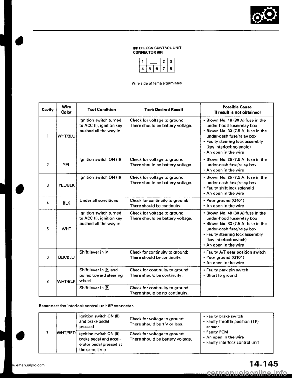
1?
4678
CavityWire
ColorTest CondhionTost: Desired RosultPossible Cause(lf result is not obtainedl
1WHT/BLU
lgnition switch turned
to ACC (l), ignition key
pushed all the way in
Check for voltage to ground:
There should be battery voltage.
Blown No. 48 {30 A} fuse in the
under-hood fuse/relay box
Blown No.33 (7.5 A) fuse in the
under-dash fuse/relay box
Faulty steering lock assembly
{key interlock solenoid)
An open in the wire
YEL
lgnition switch ON (ll)Check for voltage to ground:
There should be battery voltage.
Blown No.25 (7.5 A) fuse in the
under-dash fuse/relay box
An open in the wire
YEUBLK
lgnition switch ON (ll)Check for voltage to ground:
There should be baftery voltage.
Blown No. 25 (7.5 A) fuse in the
under-dash fuse/relay box
Faulty shift lock solenoid
An open in the wire
4BLKUnder all conditionsCheck for continuity to ground:
There should be continuity.
. Poor ground (G401)
. An open in the wire
5WHT
lgnition switch turned
to ACC (l), ignition key
pushed all the way in
Check for voltage to ground:
There should be battery voltage.
Blown No.48 (30 A) fuse in the
under-hood fuse/relay box
Blown No. 33 (7.5 A) fuse in the
under-dash fuse/relay box
Faulty steering lock assembly(key interlock switch)
An open in the wire
BLI(BLU
Shift lever in ECheck for continuity to ground:
There should be continuity,
Faulty Ay'T gear position switch
Poor ground (G101)
An open in the wire
8WHT/BLK
Shift lever in @ and
pulled toward steering
wneel
Check for continuity to ground:
There should be continuity.
Faulty park pin switch
Shon to ground
Shift lever in ECheck for continuity to ground:
There should be no continuity.
Wire side of female terminals
Reconnect the interlock control unit 8P connector.
14-145
7WHT/RED
lgnition switch ON (ll)
and brake pedal
presseo
Check for voltage to ground:
There should be 1 V or less.
Faulty brake switch
Faulty throttle position (TP)
sensor
Faulty PCM
An open in the wire
Faulty interlock control unit
lgnition switch ON (lll,
brake pedal and accel-
erator pedal pressed at
the same time
Check for voltage to ground:
There should be baftery voltage,
www.emanualpro.com
Page 803 of 1395
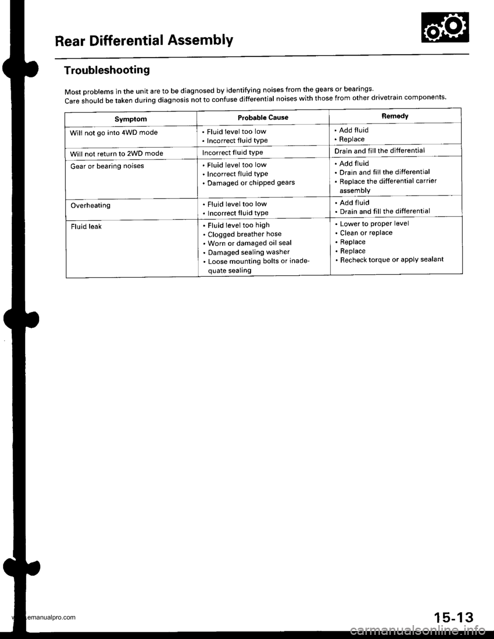
Rear Differential AssemblY
Troubleshooting
Most problems in the unit are to be diagnosed by identifying noises from the gears or bear'ngs'
care should be taken during diagnosis not to confuse differential noises with those from other drivetra'n components'
SymptomProbable CauseRemedy
Will not go into 4WD mode. Fluid level too low
. Incorrect fluid type
. Add fluid. Replace
Will not return to 2WD modeIncorrect fluid typeDrain and fill the differential
Gear or bearing noisesFluid level too low
Incorrect fluid type
Damaged or chipped gears
Add fluid
Drain and fill the differential
Replace the differential carrier
assemory
Overheating. Fluid leveltoo low
. Incorrect fluid type
. Add fluid. Drain and fill the differential
Fluid leakFluid level too high
Clogged breather hose
Worn or damaged oil seal
Damaged sealing washer
Loose mounting bolts or inade-
quate sealing
Lower to proper level
Clean or replace
Replace
Replace
Recheck torque or aPPIY sealant
15-13
www.emanualpro.com
Page 932 of 1395
![HONDA CR-V 1997 RD1-RD3 / 1.G Repair Manual
Inspection and Adjustment
Brake System Indicator
Circuit Diagram lNuLR.HorJDGNrT 0llSt!ITCHUNDEB.DASHFUSE]NEtAY BOIrllA Nl] 42 4!A
PAF�K NC BRA(E S\IICH
GBNiBEO
Io\lt j I ERAKE tuU 0 rEVEr 9!1 I(N
| HONDA CR-V 1997 RD1-RD3 / 1.G Repair Manual
Inspection and Adjustment
Brake System Indicator
Circuit Diagram lNuLR.HorJDGNrT 0llSt!ITCHUNDEB.DASHFUSE]NEtAY BOIrllA Nl] 42 4!A
PAF�K NC BRA(E S\IICH
GBNiBEO
Io\lt j I ERAKE tuU 0 rEVEr 9!1 I(N
|](/img/13/5778/w960_5778-931.png)
Inspection and Adjustment
Brake System Indicator
Circuit Diagram lNuLR.HorJDGNrT 0llSt!ITCHUNDEB.DASHFUSE]NEtAY BOIrllA Nl] 42 4!A
PAF�K NC BRA(E S\I'ICH
GBNiBEO
Io\lt j I ERAKE tuU 0 rEVEr 9!1 I(N
| oPt^r'f,'1 .r
BIKI-o-:G401
Parking Brake Switch Test
1. Remove the parking brake cover,
2. Disconnect the connector from the parking brakeswitch.
3. Check for continuity between the terminal and bodyground in each position according to the table.
Terminal
Lever Position \
Positive
TerminalBody Ground
Lever Up--o
Lever Down
NOTE (Canada): lf the parking brake switch is OK, butthe brake system indicator does not function, perform
the input test for the daytime running lights control unit(see section 23).
Brake Fluid Level Switch Test
1. Remove the reservoir cap. Check that the float
moves up and down freely; if it doesn't, replace the
reservoir cap assembly.
2. Check for continuity between the terminals in each
switch position according to the table.
- r9''r
Position12
FLOAT UP
FLOAT DOWNo
RESERVOIR CAP
GROUND
Switch contacts open atproper fluid level.
19-8
www.emanualpro.com
Page 950 of 1395
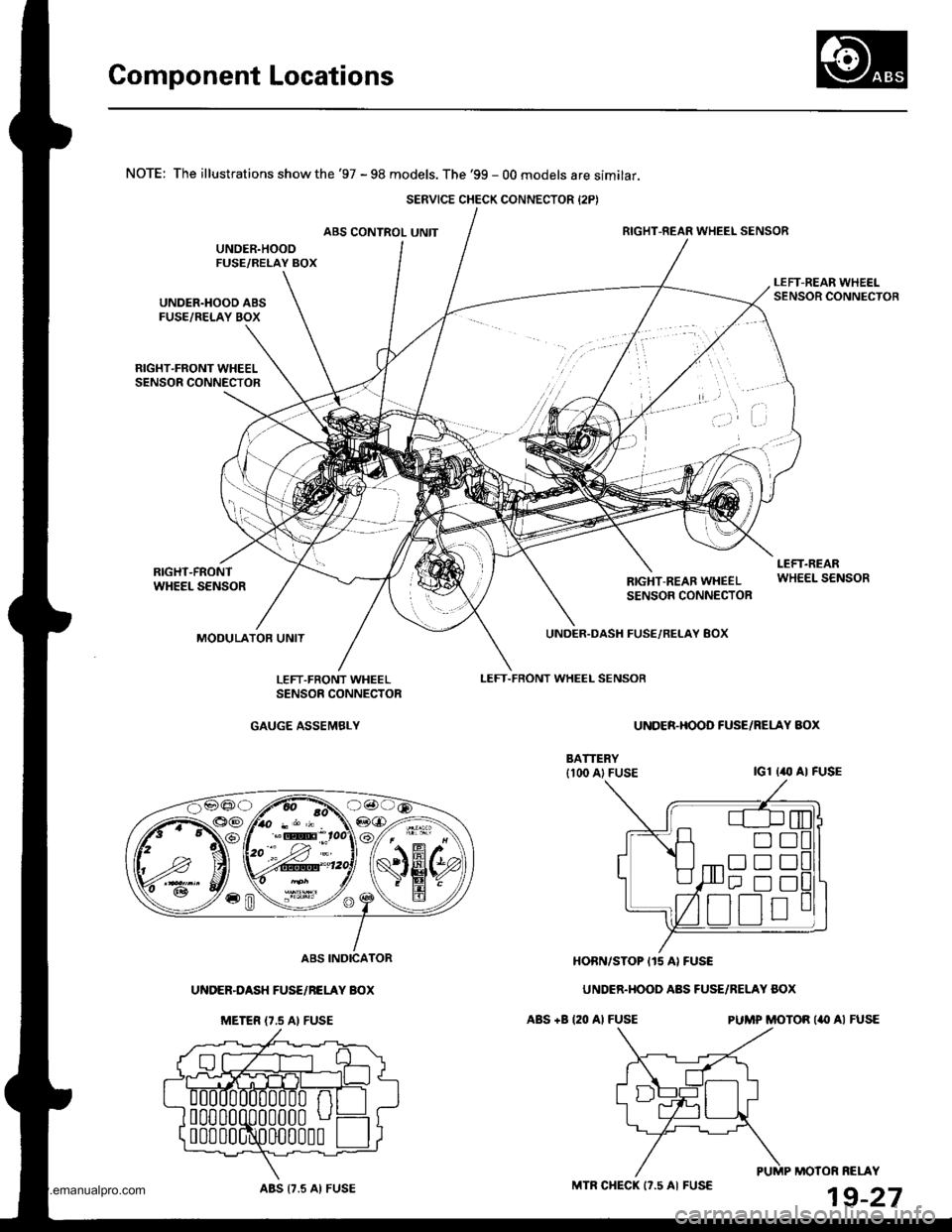
Component Locations
NOTE: The illustrations show the '97 - 98 models. The '99 - 00 models are similar.
ABS CONTROL UNITRIGHT-REAR WHEEL SENSOR
UNDER.HOOD ABSFUSE/RELAY BOX
RIGHT.FRONT WHEELSENSOR CONNECTOR
RIGHT-FRONTWHEEL SENSORRIGHT-REAB WHEELSENSOR CONNECTOR
MODULATOR UNIT
LEFT.FRONT WHEEL SENSOB
UNDER.DASH FUSE,/RELAY 8OX
UNDER.HOOO FUSE/RELAY AOX
IGl I(, AI FUSE
ABS +B 120 Al FUSEPUMP MOTOR ('II AI FUSE
HOBN/STOP I15 AI FUSE
UNDER.HOOD ABS FUSE/RELAY BOX
LEFT.FRONT WHEELSENSOE CONNECTOR
GAUGE ASSEMBLY
ABS INDICATOR
UNDER-DASH FUSE/NELAY BOX
METER {7.5 AI FUSE
MOTOR RELAY
19-27
SERVICE CHECK CONNECTOR {2PI
D!
trtrtr
[r D!
ABS {7.5 AI FUSEMTR CHECK 17.5 AI FUSE
www.emanualpro.com
Page 955 of 1395
![HONDA CR-V 1997 RD1-RD3 / 1.G Repair Manual
Circuit Diagram
UNDFS I]OOD FISAFELAY 8OXCbsod: &rrc ped. deprelled
wHT/GrN -tjF GFrlrrvril
GNITION
*oJG\*"\€F*,-
UNDER-HOOD A8S FUSE/FELAY BOX3P CONNECTOR (O number)
t_--t l-|ll"1
UNDER.HOOO A8 HONDA CR-V 1997 RD1-RD3 / 1.G Repair Manual
Circuit Diagram
UNDFS I]OOD FISAFELAY 8OXCbsod: &rrc ped. deprelled
wHT/GrN -tjF GFrlrrvril
GNITION
*oJG\*"\€F*,-
UNDER-HOOD A8S FUSE/FELAY BOX3P CONNECTOR (O number)
t_--t l-|ll"1
UNDER.HOOO A8](/img/13/5778/w960_5778-954.png)
Circuit Diagram
UNDFS I]OOD FISAFELAY 8OXCbsod: &rrc ped. deprelled
wHT/GrN -tjF GFrlrr'vril
GNITION
*oJG\'*"\€F*,-
UNDER-HOOD A8S FUSE/FELAY BOX3P CONNECTOR (O number)
t_--t l-|ll'"1
UNDER.HOOO A8S FUSE/RELAY BOX2P CONNECTOF (! numbor)
EFIAKE SWITCH CONNECTOR
l€-4| 1 txl2 |
f s a'lLr--'--.----1
UNDER,DASH FUSFJRELAY BOX20P CONNECTOR (O number)M-OD U LATOR UN IT CON N ECTOR
ll3 2ir I
{tT6TsF}
!]q:]j_1,
MP MOTOR CONNECTORnumber)
ATi)
PU
UNDER-DASH FUSE/RELAY BOX18P CONNECTOR (E number)
(tr
ASSEMBLY 5P CONNECTOR
----.4-l1)/l3l/l5l
356J89
10111213,/ 115 ,/19
123456
910'1213|i4 /718
19-32
Wire side ol female lerminals
Terminal side oJ lemale terminals
www.emanualpro.com
Page 964 of 1395
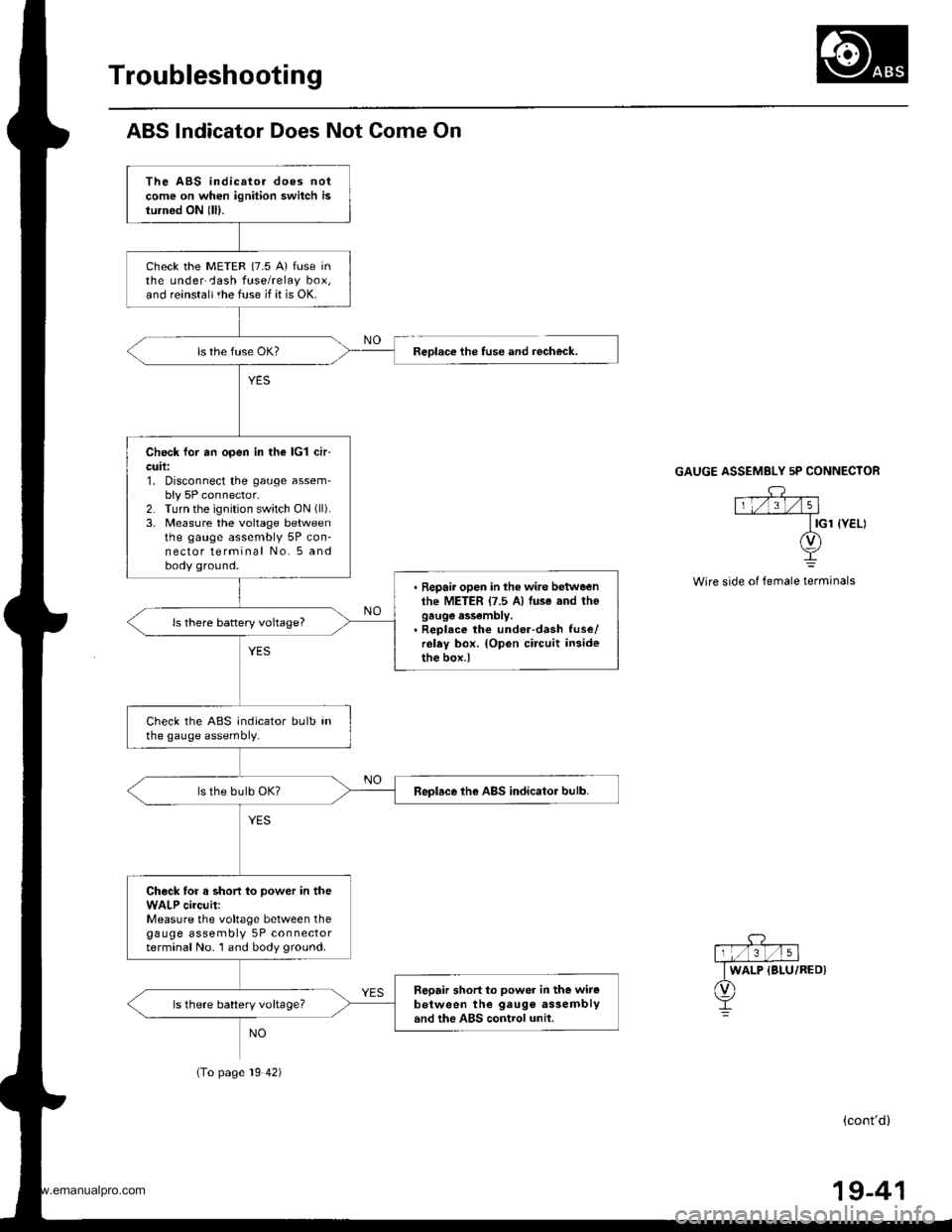
Troubleshooting
ABS lndicator Does Not Come On
The ABS indicator does notcome on when ignition switch isturnod ON lll).
check the METER {7.5 A} fuse inthe underCash fuse/relay box,and reinstaltthe fuse if it is OK.
Check for an open in the lcl ch-cuil:1. Disconnect the gauge assem-bly 5P connector.2. Turn the ignition switch ON (ll).
3. Measure the voltage betweenthe gauge assembly 5P con-nector terminal No. 5 andbody ground.
. Repair open in the wire betweenlhe METER {7.5 A) luse and thogauge assembly.. Reolece the under-dash fuse/relay box. (Opon circuit insidethe box.)
ls there battery voltage?
Check the ABS indicator bulb inthe gauge assembly.
Replace the ABS indicator bulb.
Check for a short to power in theWALP circuit:Measure the voltage between thegauge assembly 5P connectorterminal No. 1 and body ground.
Sepair short to power in the witeb€tween the gaug€ assemblyand the ABS control unil.ls there battery voltageT
Reolace the tuse and recheck.
(To page 19 42)
GAUGE ASSEMBLY 5P CONNECTOR
Wire side of female terminals
(cont'd)
19-41
www.emanualpro.com
Page 966 of 1395
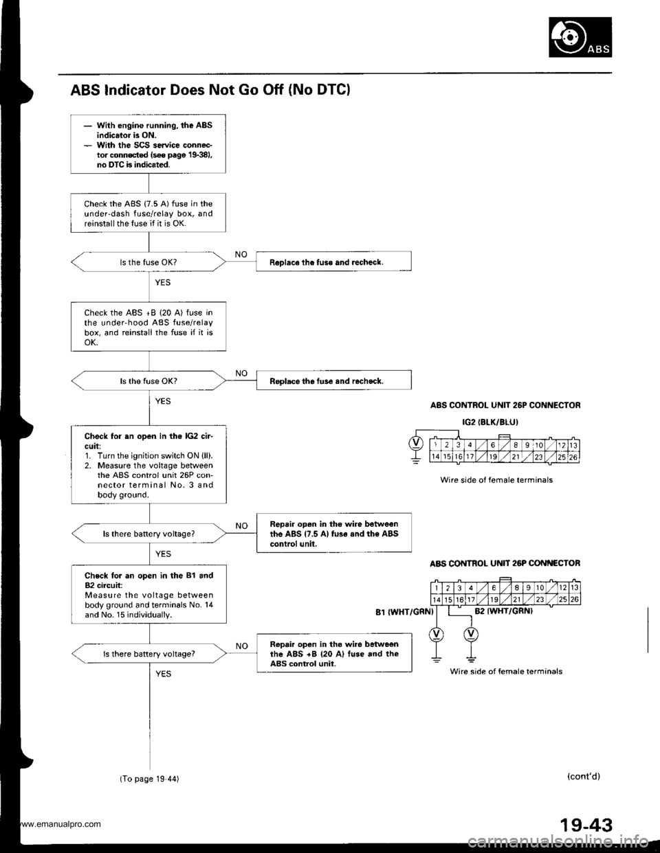
- With engine running, the ABSindicsior is ON.- With the SCS service connec-tor conn€cted (s€€ page 19381,no DTC is indicated.
Check the ABS {7.5 A) fuse in theundeFdash fuse/relay box, andreinstall the fuse if it is OK.
ReDlace lhe tuse and recheck.
Check the ABS +B (20 A) fuse inthe underhood ABS fuse/relaybox, and reinstall the fuse if it isoK.
Replace the fuse and rocheck.
Check for sn open in the lG2 cir-cuit:1. Turn the ignition switch ON {ll).2. Measure the voltage betweenthe ABS control unit 26P con-nector terminal No. 3 andbody ground.
Repair open in tho wire betweenthe ABS {7.5 A} fu3e .nd the ABScontrol unit,
Check for an open in the 81 and82 circuit:Measure the voltage betweenbody ground and terminals No. 14and No. 15 individually.
Ropair open in tho wi.e betweenrhe ABS +B {20 A) fuse and theABS control unit.is there battery voltage?
ABS Indicator Does Not Go Off (No DTGI
A8S CONTROL UNIT 26P CONNECTOR
IG2IBLK/BLU)
Wire side of female terminals
ABS CONTROL U N 26P CONf{ECTOR
{WHT/GRNI
(cont'd)
Wire side of female terminals
(To page 19 44)
19-43
www.emanualpro.com
Page 972 of 1395
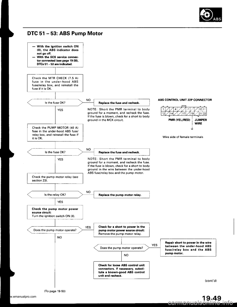
DTC 51 - 53: ABS Pump Motor
NOTE: Short the PMR terminal to bodyground for a moment, and rochock the tuse.lf the fuse is blown, check lor a shon to bodyground in the MCK circuit.
NOTE: Short the PMR terminal to bodyground for a moment, and recheck the fuse,lf the tuse is blown, check tor a short to bodyground in the wire between the under hoodABS fuse/relay box 6nd the pump motor.
ABS CONTROL UNIT 22P CONNECTOR
Wire side of female terminals
(cont'di
- Wilh the ignition switch ON{ll), the ABS indicator doesnot go ott.- With the SCS seruico connec-tor connoctod {sce page 19381,DTCa 51 - 53 .re indicated.
check the MTR cHEcK (7.5 Ailuse in the under-hood ABStuse/relay box, and reinstall theluse if it is OK.
Rsplace the fuse and rech6ck.
check the PUMP MOTOR (40 A)fuse in the under-hood ABS fuse/relay box, and reinstall the fuse ifit is oK.
Roolace lhe tusg and rocheck.
Feplace the pump motor r6ley.
Check the pump motor powelsourc€ circuit:Turn the ignition switch ON (ll).
Ch6ck fo. a short to oowd in th6pump motor power sourca circuit:Remove the pump motor relay.Does the pump motor operate?
Repair rhort to power in the wirebclweon the under-hood ABSfuse/.6lay box and ihe ABSpump motor.
Does the pump motor operateT
Ch6ck tor loos6 ABS control unitconnectors. lf necotsary, 3ubsti-tute . known-good ABS controlunit and rocheck.
(To page 19 50)
19-49
www.emanualpro.com
Page 973 of 1395
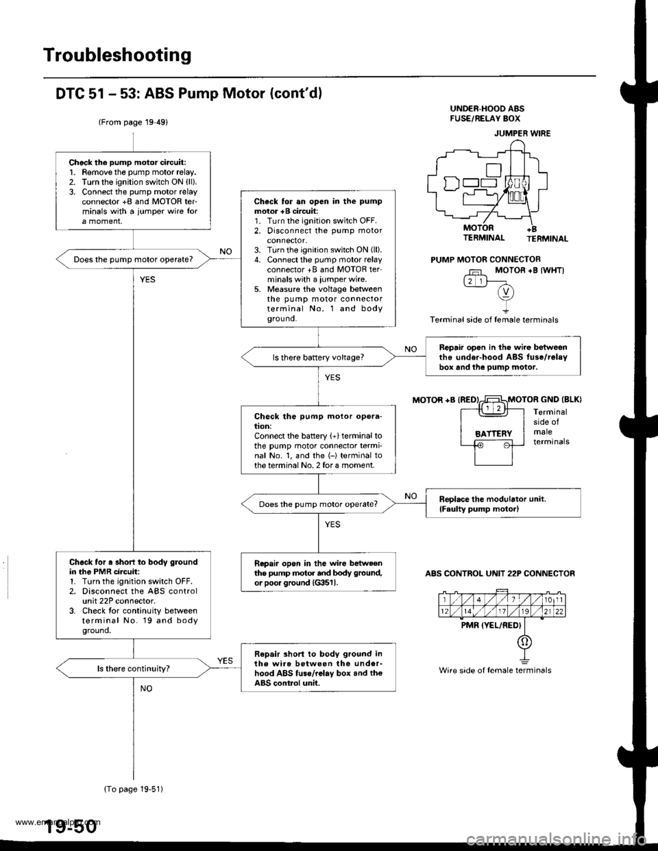
Troubleshooting
DTC 51 - 53: ABS Pump Motor (cont'dl
(From page 19 49)
UND€R-HOOO ABSFUSE/REI-AY BOX
MOTOR +B IREDIMOTOR GND IBLKI
TERMINAL TERMINAL
PUMP MOTOR CONNECTOB
Fr MOTOR +B {WHTI12 lF-(v)vI
Terminal side of female terminals
Terminalside ofmaleterminals
ABS CONTROL UNIT 22P CONNECTOR
JUMPER WIRE
Wire side of female terminals
Chock the pump motor ci.cuit:1. Remove the pump motor relay.2. Turn the ignition switch ON {ll).3. Connect the pump motor relayconnector +B and MOTOR ter-minals with a jumpor wire fora moment,
Check for an open in the pump
motor +B circuit:1. Turn the ignition switch OFF.2. Disconnect the pump motor
3. Turn the ignition switch ON (ll).
4. Connect the pump motor relayconnector +B and MOTOR terminals with a iumper wire.5. Measure the voltage beaveenthe pump motor connectorterminal No. l and bodygrou nd.
Does the pump motor operate?
Bepair opon in the wire botweenthe under-hood ABS fuse/relavbor and the pump motor.ls there battery voltage?
Check the pump motor opera-tion:Connect the battery (+)terminal tothe pump motor connector termi-nal No. 1, and the (-) terminal tothe terminal No. 2 for a moment.
Reolace the modulator unit.
lFaulty pump moto.lDoes the pump motor operate?
Ch6ck for a short to body groundin the PMR circuit:1. Turn the ignition switch OFF.2. Disconnect the ABS controlunit 22P connector.3. Check tor continuity betweenterminal No. 19 and bodyground.
Repair open in the wire bstweenthe pump motor and body ground,
or poo. ground {G3511.
Repair short to body ground inthe wir6 botween the under-hood ABS tuse/rclay box and th€ABS contlol unit.
{To page 19-51)
www.emanualpro.com