fuse HONDA CR-V 1997 RD1-RD3 / 1.G User Guide
[x] Cancel search | Manufacturer: HONDA, Model Year: 1997, Model line: CR-V, Model: HONDA CR-V 1997 RD1-RD3 / 1.GPages: 1395, PDF Size: 35.62 MB
Page 203 of 1395
Goolant Temperature Gauge
Gauge Testing
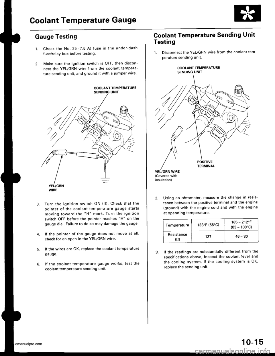
1. Check the No. 25 (7.5 A) fuse in the under-dash
fuse/relay box before testin9.
2. Make sure the ignition switch is OFF, then discon-
nect the YEL/GRN wire from the coolant tempera-
ture sending unit. and ground it with a jumper wire.
YEL/GRNWIRE
Turn the ignition switch ON {ll). Check that the
pointer of the coolant temperature gauge starts
moving toward the "H" mark. Turn the ignition
switch OFF before the pointer reaches "H" on the
gauge dial. Failure to do so may damage the gauge.
lf the pointer of the gauge does not move at all,
check for an open in the YEL/GRN wire.
lf the wires are OK, replace the coolant temperature
gauge.
lf the coolant temperature gauge works, test the
coolant temperature sending unit.
5.
COOLANT TEMPERATURE
Coolant Temperature Sending Unit
Testing
1. Disconnect the YEUGRN wire from the coolant tem
perature sending unit.
COOLANT TEMPERATURE
POSITIVETERMINAL
YEL/GRN WIRE(Covered withinsulation)
2. Using an ohmmeter, measure the change in resis-
tance between the positive terminal and the engine
(ground) with the engine cold and with the engine
at operating temPerature.
Temperature133.F (56'C)1A5 - 212F
(8s - 100'c)
Resistance(0)13746-30
3. lf the readings are substantially different from the
specitications above, inspect the coolant level and
the cooling system. lf the cooling system is OK,
replace the sending unit.
10-15
www.emanualpro.com
Page 218 of 1395
![HONDA CR-V 1997 RD1-RD3 / 1.G User Guide
Electrical Connections -97 Model
f_ --- --- -t _l-1r -lla^^^ tirrnl
(.J
no 3wrcx (-]lrLt -o.:\-tlDl"ii
\
HT:
v
l-I
tl
I-6,
I
4
^li lGPlf----;;ltl
tl
T
FUEL lltlEcToes
oa 9I3
aEt30F
TDC3ErcON
ct HONDA CR-V 1997 RD1-RD3 / 1.G User Guide
Electrical Connections -97 Model
f_ --- --- -t _l-1r -lla^^^ tirrnl
(.J
no 3wrcx (-]lrLt -o.:\-tlDl"ii
\
HT:
v
l-I
tl
I-6,
I
4
^li lGPlf----;;ltl
tl
T
FUEL lltlEcToes
oa 9I3
aEt30F
TDC3ErcON
ct](/img/13/5778/w960_5778-217.png)
Electrical Connections -'97 Model
f_ --- --- -t _l-1r -lla^^^ tirrnl
(.J
no 3wrcx (-]lrLt -'o.:\-'tlDl"ii
\
HT:
v
l-I
tl
I-6,
I
4
' ^li lGPlf----;;ltl
tl
T
FUEL ll'tlEcToes
oa 9I3
aEt30F
TDC3ErcON
ctPSErAOi
CKF3EN30F
TO EIIF-
*f
ctovEu
A' lGI
aztL@,
Xo.2|NJ2 3
ca tDcP[{J3 A2
cra Tltcl
||tL
Gt ct(iP?
er2 cxP{
cfl ct(Ftr
1
Dta ELtr
c|| v!]3TL T'
t ^cc ^r?to l/C CLUTCfl BELAYto i^Ol^toh F tl REI Y,@III'C|{AEi FA'I iEL Y
rtT
c. K.uirEuNxcoi||lEctoh
SERVICECl|ECK@ NEqroi
I ^ca 6
d__-lb
qr 3c3
ilaALTF CI'
rt: usAEII ATPI{PE
6uI)r^ l
t*frl
E
t'-
bI. ATPfi
B2a AtPtX
E' TPDI
Att lEFOgn3wltc
gi7 alP:l
I
I
ON
Ei. ATPID{ND tir
FUSES :(D BACK uP (RADro) (7.sr0.
@ "o^n ttot (tuo)'(D BATfERY (IOOA) *
o rcl (4oA)*
GAIXIEASSEIBLY
(DFt E/ flsA).@ No.13 FUEL PU P ('l5A)
O No. 2s METER (7.5A)(D NO. 'I5 ALTERNATOR SP SENSOB (7.5A) *
O No. 3i STABTER SIGNAL (7.5A)*: In lhc und?r.lrood tu$/rclay bor
(cont'd)
1 1-15
www.emanualpro.com
Page 225 of 1395
![HONDA CR-V 1997 RD1-RD3 / 1.G User Guide
System Description
Electrical Gonnections -97 Model lcontd)
|l/8LU l IU
t,l
T
WHT/€LU
wltT/BLr((
WHT/BLK
wltT/GRt{
,J
I.l
c352
CRN/FEO
BLU/ORN
GRI{/F€O
ALU/IVHT
T"*,,*.
UNOER]IOODfUSE,/FEIAY 8 HONDA CR-V 1997 RD1-RD3 / 1.G User Guide
System Description
Electrical Gonnections -97 Model lcontd)
|l/8LU l IU
t,l
T
WHT/€LU
wltT/BLr((
WHT/BLK
wltT/GRt{
,J
I.l
c352
CRN/FEO
BLU/ORN
GRI{/F€O
ALU/IVHT
T"*,,*.
UNOER]IOODfUSE,/FEIAY 8](/img/13/5778/w960_5778-224.png)
System Description
Electrical Gonnections -'97 Model lcont'd)
|l/8LU l IU
t,l
T
WHT/€LU
wltT/BLr((
WHT/BLK
wltT/GRt{
,J
I.l
c352
CRN/FEO
BLU/ORN
GRI{/F€O
ALU/'IVHT
T"*,,*.
UNOER]IOODfUSE,/FEIAY 8OX
IVTII/BLU -
".* _f
IBtur,tvrr
IBLU/W8T -.'|
,ato"n L
;rfi
""r _g!:f
BLK/FED 'I_
FUSE/BELAY BOX
*2: USA
rcl ({0A}
HOiX sIOf 05A)
r'tc3r srAaIESSG|I|^L 05 )
11-22
www.emanualpro.com
Page 238 of 1395
System Description
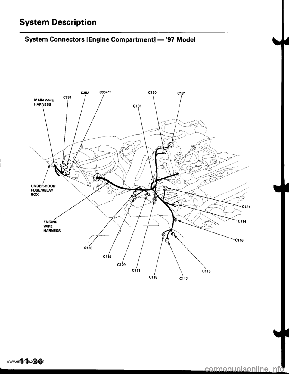
System Gonnectors [Engine Compartmentl -'97 Model
MAIN WIREHARNESS
UNOER.HOODFUSE/RELAY80x
1 1-36
..'.'.'
ct21
cl11
cl16
www.emanualpro.com
Page 248 of 1395
![HONDA CR-V 1997 RD1-RD3 / 1.G User Guide
System Description
System Connectors lEngine Gompartment] -98 Model
MAIN WIREHARNESS
UNDER.HOODFUSE/RELAYBOX
ENGINEw|REHARNESS
*2: USA
11-46
www.emanualpro.com HONDA CR-V 1997 RD1-RD3 / 1.G User Guide
System Description
System Connectors lEngine Gompartment] -98 Model
MAIN WIREHARNESS
UNDER.HOODFUSE/RELAYBOX
ENGINEw|REHARNESS
*2: USA
11-46
www.emanualpro.com](/img/13/5778/w960_5778-247.png)
System Description
System Connectors lEngine Gompartment] -'98 Model
MAIN WIREHARNESS
UNDER.HOODFUSE/RELAYBOX
ENGINEw|REHARNESS
*2: USA
11-46
www.emanualpro.com
Page 252 of 1395
![HONDA CR-V 1997 RD1-RD3 / 1.G User Guide
System Description
System Gonnectors lEngine Compartment] -99 - 00 Models
MAIN WIREHAENESS
UNDER.HOOOFUSE/RELAYBOX
ENGINEWIREHARNESS
www.emanualpro.com HONDA CR-V 1997 RD1-RD3 / 1.G User Guide
System Description
System Gonnectors lEngine Compartment] -99 - 00 Models
MAIN WIREHAENESS
UNDER.HOOOFUSE/RELAYBOX
ENGINEWIREHARNESS
www.emanualpro.com](/img/13/5778/w960_5778-251.png)
System Description
System Gonnectors lEngine Compartment] -'99 - 00 Models
MAIN WIREHAENESS
UNDER.HOOOFUSE/RELAYBOX
ENGINEWIREHARNESS
www.emanualpro.com
Page 263 of 1395
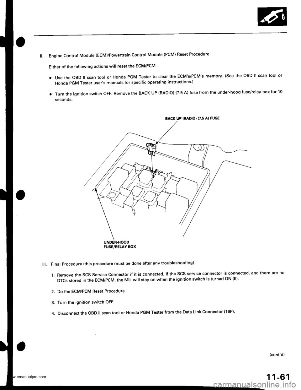
ll. Engine Controt Module (EcM)/Powertrain Control Module {PCM) Reset Procedure
Either of the following actions will reset the ECM/PCM.
. use the oBD ll scan tool or Honda PGM Tester to clear the ECM'�s/PCM'�s memory. (see the oBD ll scan tool or
Honda PGM Tester user's manuals for specific operating instructions )
. Turn the ignition switch oFF. Remove the BACK UP (RADIO) (7.5 A) fuse from the under-hood fuse/relay box for 10
seconos.
lll. Final Procedure {this procedure must be done after any troubleshooting)
1. Remove the SCS Service Connector if it is connected. lf the SCS service connector is connected. and there are no
DTCS stored in the ECM/PCM, the MIL will stay on when the ignition switch is turnsd oN (ll).
2. Do the ECM/PCM Reset Procedure.
3. Turn the ignition switch OFF
4. Disconnect the OBD ll scan tool orHonda PGM Tester from the Data Link Connector ( 16P)'
(cont'd)
1 1-61
BACK UP {RADIOI I7,5 AI FUSE
FUSE/RELAY BOX
www.emanualpro.com
Page 284 of 1395
PGM-FI System
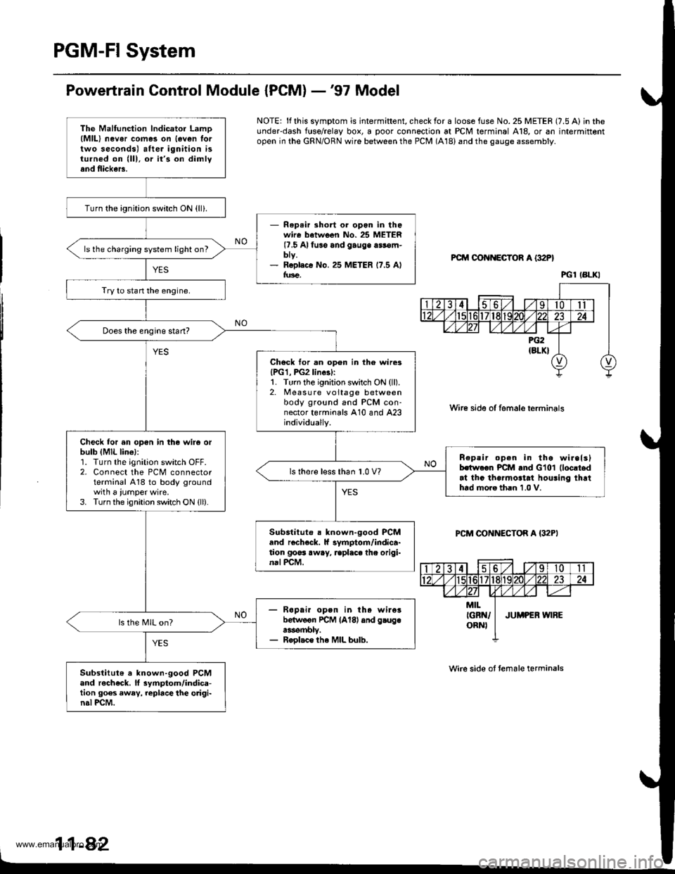
Powertrain Control Module {PCM} -'97 Model
NOTE: lf this symptom is intermiftent, check for a loose fuse No. 25 METER (7.5 A) in theunderdash f{rse/relay box, a poor connection at PCM terminal A18, or an intermittentopen in the GRN/ORN wire between the PCM (A18) and the gauge assembly.
PCM OON ECTOR A {32P}
Wire side of female terminals
PCM CONNECTOR A {32PI
Wire side ot temale terminals
11-42
The Malfunction lndicator LamD(MlL) nev6r comes on {even lortwo seconds) after ignition isturned on (lll, or it's on dimlyand flickers.
Turn the ignition switch ON {ll}.
- Rep.ir short or opon in thowire batween No. 25 METER(7.5 Alfuso and gauge a$€m-bty.- R6pl.c€ No. 25 METER 17.5 Alfus€.
ls the charging system light on?
Try to stan the engine.
Does the engine start?
Chock tor.n open in th6 wire3{PG1, PG2linesl:1. Turn the ignition switch ON (ll).2. Measure voltage betweenbody ground and PCM con-nector terminals A10 and A23individually.
Check for an op€n in the wir6 orbulb (MlL lin€l:1. Turn the ignition switch OFF.2. Connect the PCM connectorterminal A18 to body groundwith a iumper wire.3. Turn the ignition switch ON {ll).
n€peir open in tho wirelslhwoon PCM and Glol (loc!t.d
at thc tha.mo3tat houling thrthtd moro th.n 1.0 V.
ls thore l€ss than 1.0 V?
Substituto . known-good PCMand r€check. ll symptom/indica-tion goss away, rcplaca the origi-nal PCM.
- R6pai. open in th. wileibelwoon rcM lAl8l dnd g.ugea3rombly.- Roolac€ the MIL bulb.
ls the MIL on?
Substitut6 a known-good PCMand rocheck. ll 3ymptom/indica-tion goes away, replace the o.igi-n.l PCM.
PGl IBLKI
www.emanualpro.com
Page 285 of 1395
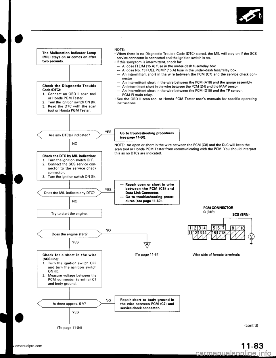
NOTE:. When there is no Diagnostic Trouble Code (DTC) stored, the MIL will stay on if the SCSservice connector is connected and the ignition switch is on.. lf this svmotom is intermittent, check for:- A loose Fl E/M (15 Aifuse in the underdash tuse/relay box- A loose No. 13 FUEL PUMP {15 A) fuse in the under-dash fuse/relay box- An intermittent short in the wire between the PCM (C7) and the service check con-
- An intermittent short in the wire between the PCM (A18) and the gauge assembly- An intermittent shon in the wire betlveen the PCM (D4) and the MAP sensor- An intermiftent short in the wire between the PCM {D10) and the TP sensor.PGM-Fl main relay.'See the OBD ll scan tool or Honda PGM Tester user's manuals lor specilic operatinginstructions,
NOTE: An open or short in the wire between the PCM (C8) and the DLC will keep thescan tool or Honda PGM Tester lrom communicating with the PCM. You should ioterpretthis as no DTCS are indicated.
PCM CONNECTORc l3lPl scs .BRNI
lTo page 11 84)Wire sid6 of f€male terminalg
(cont'dl
11-83
The Malfunciion lndicator Lamo{MlL) stavs on o. comes on afteltwo seconds,
Check the Oiegnosiic TroubleCode (DTC):
1. Connect an OBD ll scan toolor Honda PGM Tester.2. Turn the ignition switch ON 1lli.3. Read the DTC with the scantool or Honda PGII Tester.
Go to troubleshooting procedures(s€€ page 11501.Are any DTCIs) indicated?
Ch6ck lh6 DTC by MIL indication:1. Turn the ignition switch OFF.2. Connect the SCS service con-nector to the service checkconnector.3. Turn the ignition switch ON (ll).
- Repair opon or short in wi.6between the PCM (C8) andData Link Connector.- Go to troubloshooting proce-
dur€s {3ee page 11-601.
Does the MIL indicate any DTc?
Try to start the engine.
Does the engine start?
Check tor a short in the wire{SCS line):1. Turn the ignition switch OFFand turn the ignition switchoN flt).2. Measure voltage between thePCM connector terminal C7and body ground.
Repair short to body ground inthe wire between PCM lCTl andservice check connector.ls there approx. 5 V?
(To page 1'l-84)
www.emanualpro.com
Page 286 of 1395
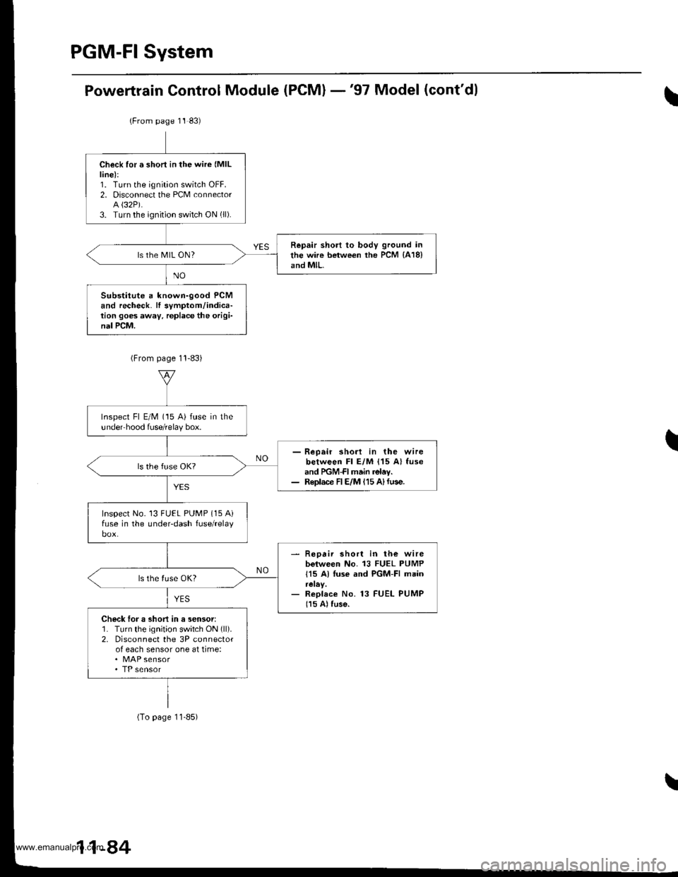
Powertrain Control Module (PCM) -'97 Model (cont'dl
(From page 11 83)
Check for a short in the wire (MlL
line):1. Turn the ignition switch OFF.2. Disconnect the PCM connectorA {32P).3. Turn the ignition switch ON (ll).
Repair short to body ground inthe wire between the PCM {418}and MlL.ls the MIL ON?
Substitute a known-good PCMand recheck. lf symptom/indica-tion goes away. replace the origi-nal PCM.
Inspect Fl E/M (15 A) fuse in theundeFhood fuse/relay box.
- Reoair shod in the wirebetween Fl E/M {15 A} fuseand PGM-FI main relav.- Replace FIE/M 115 A)fuse.
Inspect No. 13 FUEL PUMP (15 Aifuse in the underdash fuse/relay
- Repair short in lh€ wirebolween No. 13 FUEL PUMP
115 A) Iuse and PGM-FI main
- Replace No. 13 FUEL PUMP
115 A) fuse.
Check loJ a short in a sensor:1. Turn the ignit;on switch ON (ll).
2. Disconnect the 3P connectorof each sensor one at time:. MAP sensor
(To page 11-85)
11-84
www.emanualpro.com