Valve body HONDA CR-V 1997 RD1-RD3 / 1.G Repair Manual
[x] Cancel search | Manufacturer: HONDA, Model Year: 1997, Model line: CR-V, Model: HONDA CR-V 1997 RD1-RD3 / 1.GPages: 1395, PDF Size: 35.62 MB
Page 716 of 1395
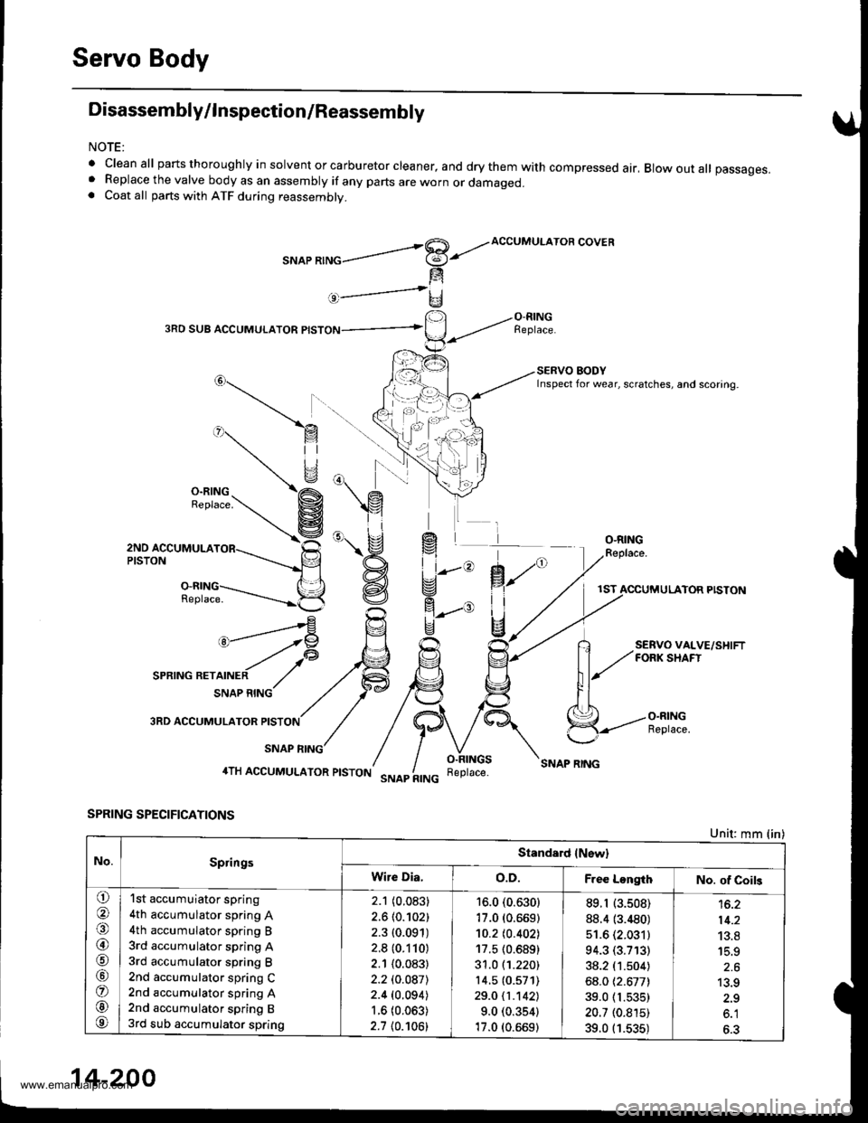
Servo Body
Disassembly/lnspection/Reassembly
NOTE:
' cleanall parts thoro ugh ly in solvent or ca rbu retor clea ner, a nd dry them with compressed air, Blow out all passages.. Replace the valve body as an assembly if any parts are worn or damaged.. Coat all parts with ATF during reassembly.
ACCUMULATOR COVER
3RO SUB ACCUMULATOR
O-RINGFeplace.
SERVOFORK S
fi,
il
g
1ST ACCUMULATOR PISTON
Replace.
RVO VAL\IRK SHAFT
O.RING
VE/SHIFT
3RD ACCUMULATOR
SPRING SPECIFICATIONS
\_)
SNAP RING
SNAP RING
Unit: mm {in)
@"- -tP
-.t l@SPR|NG RETATNER ,/
No.SpringsStandard lNewl
Wire Dia,o.D.Free LongthNo. of Coil3
o
@J6
@.A
\o,
o
@
@
1st accumuiator spring
4th accumulator spring A
4th accumulator spring B
3rd accumulator spring A
3rd accumulator spring B
2nd accumulator spring C2nd accumulator spring A2nd accumulator spring B
3rd sub accumulator spring
2.1 (0.083)
2.6 {0.102)
2.3 (0.091)
2.8 (0.110)
2.1 (0.083)
2.2 (0.087l-
2.4 (0.094)
r.6 (0.063)
2.7 {0.106)
16.0 (0.6301
17.0 (0.669)'t0.2 t0.402]�
17.5 (0.689)
31.0 (1.220)
14.5 {0.571)
29.0 11.1421
9.0 (0.354)
17.0 (0.669)
89.r (3.508)
88.4 (3.480)
51.6 (2.031)
94.3 (3.713)
38.2 (1.504)
68.0 {2.677)
39.0 fi.535)
20.7 (0.815)
39.0 (1.535)
14.2
13.8
15.9
2.6
13.9
2.9
o.l
6.3
14-200
www.emanualpro.com
Page 717 of 1395
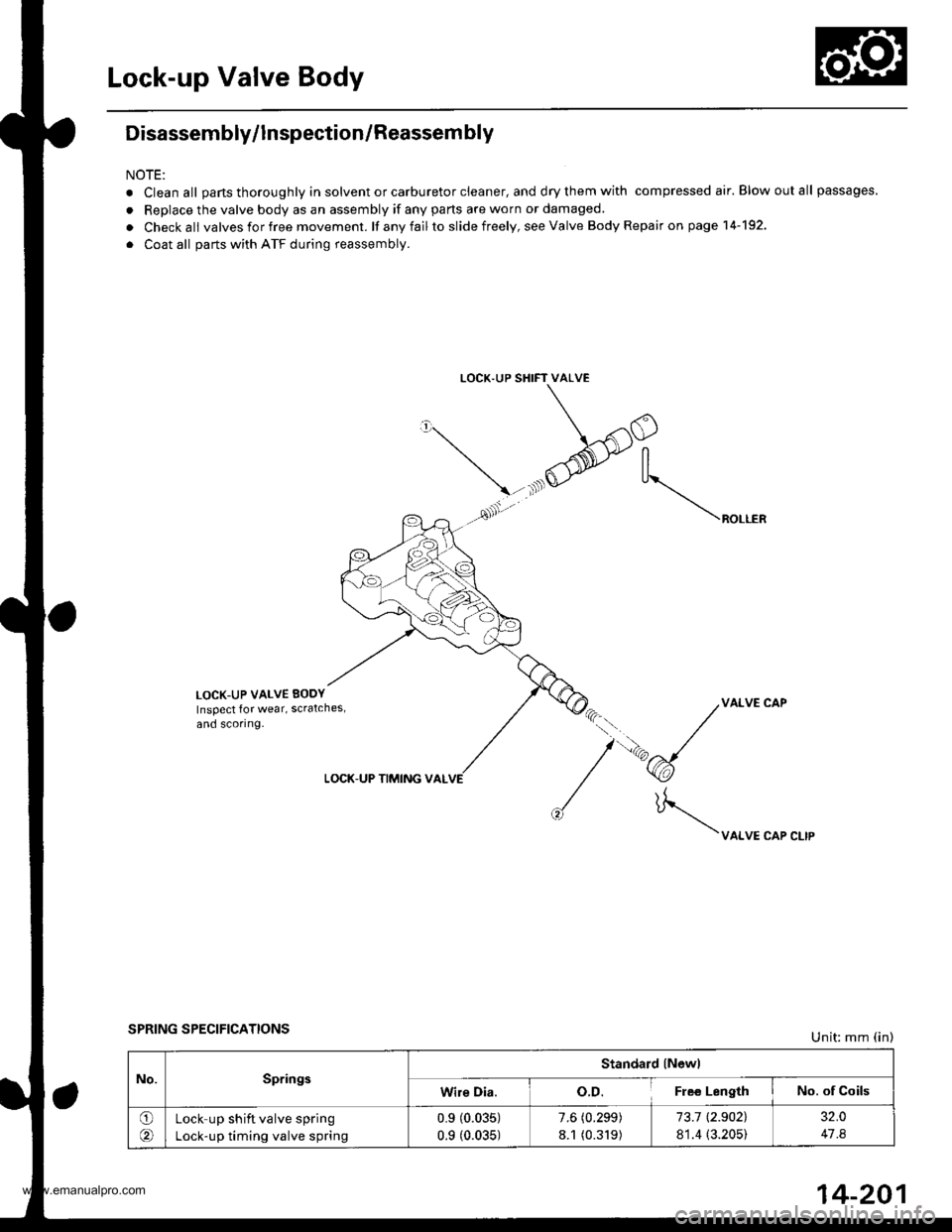
Lock-up Valve Body
Disassembly/lnspection/Reassem bly
NOTE:
. Clean all parts thoroughly in solvent or carburetor cleaner, and dry them with compressed air. Blow out all passages.
. Replace the valve body as an assembly if any parts are worn or damaged.
. Checkall valvesforfree movement. lf anyfailto slide freely, seeValve Body Repairon page 14-192.
. Coat all parts with ATF during reassembly.
LOCK.UP SHIFT VALVE
\/'
\-.xlO
@-tr
, ^ ,As'. \"o...*
LOCK-UP VALVE EODY
Inspect lor wear, scratches,
and scoring.
VALVE CAP
\uo.*"or".,,
LOCK-UP TIMING VAL
SPRING SPECIFICATIONSUnit: mm (in)
No.SpringsStandard lNewl
Wire Dia.o.D.Fle€ LengthNo. of Coils
O(Lock up shift valve spring
Lock-up timing valve spring
0.9 (0.035)
0.9 (0.035)
7.6 (0.299)
8.1 (0.319)
73.1 t2.902),
81.4 (3.205)
32.0
47 .8
14-201
www.emanualpro.com
Page 766 of 1395
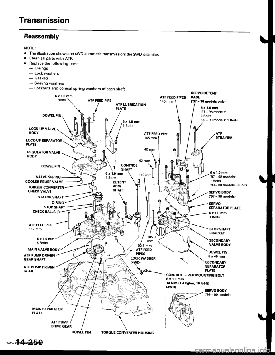
Transmission
Reassembly
NOTE:
. The illustration shows the 4WD automatic transmission; the 2WD is similar.. Clean all parts with ATF.. Replace the following parts:- O-rings- Lock washers- Gaskets- Sealing washers- Locknuts and conical spring washers of each shaft
ATF FEED PIPE
/
ATF FEED PIPES145 mm
SERVO DETENTBASE(37 -98 modeb onlylATF LUBRICATIONPLATE6x1.0mm
2 Bolts'99 - 00 models: 1 Bolts
LOCK.UP VALVEBODY
LOCK.UP SEPARATORPLATE
REGULATOR VALVEBODY
DOWEL PIN
DOWEL PIN
VALVE SPRING
STATOR SHAFT
'-
'112mmll,
rlT
ATFSTRAINER
40 mm
j coNrRoLI SHAFT
COOLER BELIEF VALVE
TOROUE CONVERTERCHECK VALVE
6x1.0mm18olts
DETENTARMSHAFT
6x1,0mm'97 - 98 models:7 Bolts'99 - 00 models:8 Bolts
SERVO BODY('97 - 98 models)
SERVOSEPARATOR PLATE
6x1.0mm3 Bolts
STOP SHAFTBRACKET
SECONDARYVALVE BODY
OOWEL PIN8x40mm
O.RING
STOP SHAFTCHECK BALLS 18'
ATF FEED PIPE112 mm
6x1.0mm5 Eolts
ATF PUMP DRIVENGEAR SHAFT
ATF PUMP DRIVEN
MAIN SEPARATORPLATE
MAIN VALVE EOOY
SECONDARYSEPARATOR
d---.- PLATE--.- CONTROL I.EVER MOUNTING BOLT6x1.0ftm14 N.m (1.4 kgt.m, 10 tbf.ft)(4WD)SERVO BODY('99 - 00 models)
ATF PUMP
6x1.0mm
ATF FEEO PIPE
) / 105.8
/,,!.,::(./ afF FEEO,/ ptpEs
EP,---!ir{+*a r
fpffi4 i
x*hi
_ \zl
14-250
DRIVE GEAR
DOWEL PINTOBOUEHOUSING
www.emanualpro.com
Page 767 of 1395
1.Install the suction pipe collar and the ATF magnet
{2WD) in the torque converter housing, if necessary.
lnstall the main seDarator Dlate and the two dowel
pins on the torque converter housing,
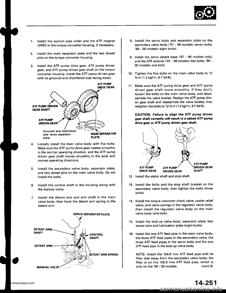
Install the ATF pump drive gear. ATF pump driven
gear, and ATF pump driven gear shaft on the torque
converter housing. Installthe ATF pump driven gear
with its grooved and chamfered side facing down.
ATF PUMPGEAR
ATF PUMP D{IVEf{GEAR SHAFT
ATF PUi'PORIVEN GEAR
Grooved and chamteredside faces separatorplate.
MAIN S€PAR/ATORPLATE
5.
o.
Loosely install the main valve body with five bolts.
Make sure the ATF pump drive gear rotates smoothly
in the normal operating direction, and the ATF pump
driven gear shaft moves smoothly in the axial and
normal operating directions.
Install the secondary valve body, separator plate,
and two dowel pins on the main valve body. Do not
installthe bolts.
Install the control shaft in the housing along with
the manual valve.
lnstall the detent arm and arm shaft in the main
valve body, then hook the detent arm spring to the
detent arm.
SEBVO SEPARATOR PLATE
7.
DETENT ARMSHAFT
OETENT ARM
CONTROLSHAFT
MANUAL VAIVE
OETENT ARM SPRING
onlv on the '98 - 00 models,
14-251
1l.
9.
8.
10.
Install the servo body and separator plate on the
secondary valve body ('97 - 98 models: seven bolts,'99 - 00 models: eight bolts).
lnstall the servo detent base ('97 - 98 models only)
and the ATF strainer ('97 - 98 models: two bolts,'99 -
00 models: one boltl.
Tighten the five bolts on the main valve body to 12
N'm (1.2 kgf.m, 8.7 lbf.ft).
Make sure the ATF pump drive gear and ATF pump
driven gear shaft move smoothly. lf they don't,
loosen the bolts on the main valve body, and disas-
semble the valve bodies. Realign the ATF pump driv-
en gear shaft and reassemble the valve bodies, then
retighten the bolts to 12 N.m (1.2 kgim, 8.7 lbf.ft).
CAUTION: Failure to align the ATF pump driven
gear shaft corroctly will rosult in a seizsd ATF pump
drive gear or ATF pump drivon gear shaft.
ATF PUMP ATFGEARDRIVE GEAR DBIVEN GEARSHAFT
Install the stator shaft and stop shaft
Install the bolts and the stop shaft bracket on the
secondary valve body, then tighten the bolts (three
bolts).
Install the torque converter check valve, cooler relief
valve, and valve springs in the regulator valve body,
then install the regulator valve body on the main
valve body {one boltl.
Install the lock-up valve body, separator plate, two
dowel pins and lubrication plate (eight bolts).
Installthe one ATF feed pipe in the main valve body,
the three ATF feed pipes in the secondary valve, the
three ATF feed pipes in the servo body and the one
ATF feed pipe in the lock-up valve body.
NOTE: lnstall the 105.8 mm ATF feed pipe with its
filter side away from the secondary valve body; the
filter is on the 105.8 mm ATF feed pipe, which is(cont'd)
13.
14.
15.
16.
www.emanualpro.com
Page 795 of 1395
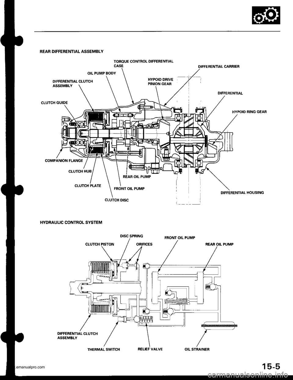
TOROUE CONTROL OIFFERENTIAL
REAR DIFFERENTIAL ASSEMBLY
OIL PUMP BODY
OIFFERENTIAL CLUTCHHYPOID DRIVEPINION GEAR
OIFFERENTIAL CARRIER
DIFFERENTIAL
HYPOID RING GEAR
DIFFERENTIAI- HOUSING
REAR OII- PUMP
ASSEMBLY
CLUTCH GUIDE
COMPANION FLANG€
CLUTCH HUB
CLUTCH PLATE
HYDRAULIC CONTROL SYSTEM
CLUTCH PISTON
CLUTCH DISC
REAR OIL PUMP
FRONT OIL PUMP
DISC SPRINGFRONT OIL PUMP
DIFFEREMT|AL CLUTCHASSEMBI-Y
THERMAL SWITCHRELIEF VALVEOIL STRAINER
15-5
www.emanualpro.com
Page 848 of 1395
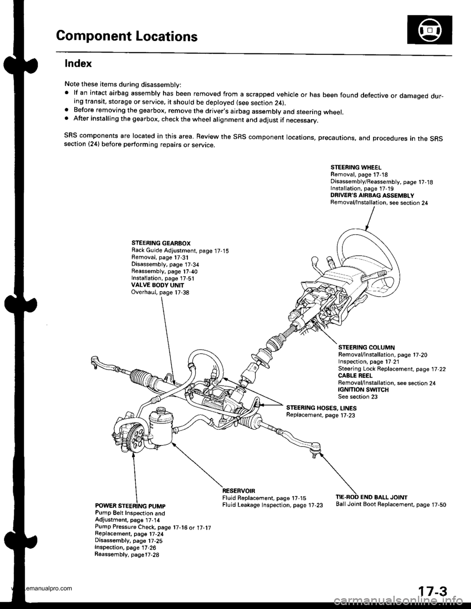
Component Locations
lndex
Note these items during disassembly:' lf an intact airbag assembly has been removed from a scrapped vehicle or has been found defective or damaged dur-ing transit, storage or service. it should be deployed (see section 24),a Before removing the gearbox, remove the driver.s airbag assembly and steering wheel.. After installing the gearbox, check the wheel alignment and adjust if necessary.
SRS components are located in this area. Review the SRS component locations, precautions, and procedures an the SRssection (24) before performing repairs or servrce.
STEERING WHEELRemoval, page 17,18Disassembly/Reassembly, page 1?,18Installation, page 17-19DRIVER'S AIRBAG ASSEMBLYRemoval/lnstallation, see section 24
STEERING GEARBOXRack Guide Adjustment, page 17-15Removal, page 17-31Disassembly, page 17-34Reassembly, page 17,40Installation, page 17,51VALVE BODY UNITOverhaul, page 17-38
STEERING COLUMNRemoval/lnstallation. page 17-20Inspection, page l7 21Steering Lock Replacement, page 17 22CABLE REELRemoval/lnstallation, see section 24tcNrnoN swtTcHSee s€ction 23
STEERING HOSES, LINESReplacement. page l7-23
Pump Belt Inspection andAdjustment, pag€ t7-14Pump Pressure Check, page 17-16 ot 17-1jReplacemont, page 17-24Disassembly, pa96 17,25Inspection, page 17-26Reassembly. page17-28
RESERVOIRFluid R6placement. page 17 15Fluid Leakage lnspection, page 17-23
END BALL JOINTBallJoint Boot Replacement, page 17-50
17-3
www.emanualpro.com
Page 849 of 1395
Troubleshooting
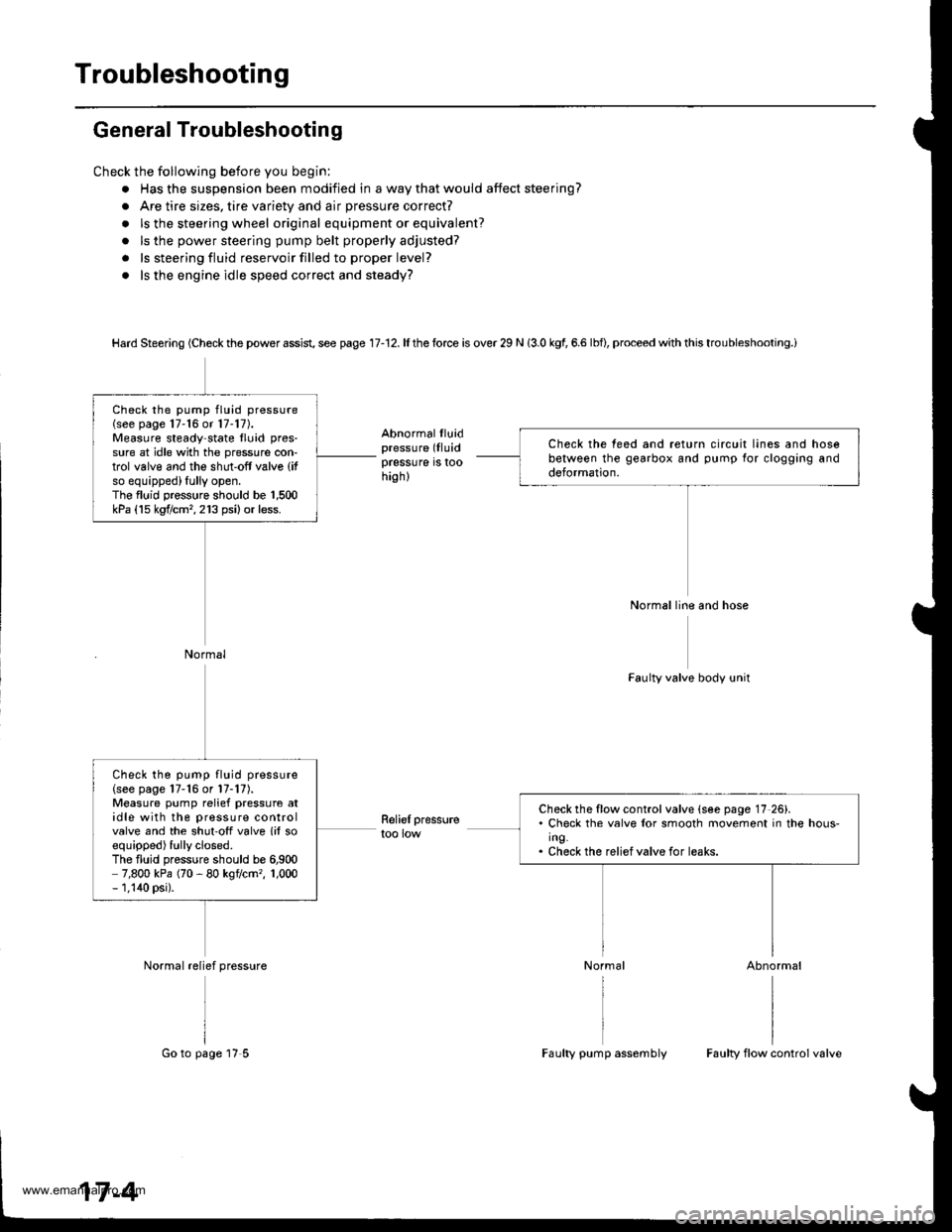
General Troubleshootin g
Check the following before you begin:
. Has the suspension been modified in a way that would affect steering?
. Are tire sizes, tire variety and air pressure correct?
. ls the steering wheel original equipment or equivalent?
. ls the power steering pump belt properly adjusted?
. ls steering fluid reservoir filled to proper level?
. ls the engine idle speed correct and steady?
Hard Steering (Check the power assist, see page 17-12. lf the force is over 29 N (3.0 kgl 6.6 lbfl, proceed with this troubleshooting.i
Abnormalthiidpressure (Iluidpressure is toohigh)
Relief pressuretoo low
Faulty valve body unit
Abnormal
Check the teed and return circuit lines and hosebetween the gearbox and pump for clogging anddeformation.
Normal line and hose
Check the pump fluid pressure(see page 17-16 or 17-17).Measure steady state lluid pres-
sure at idle with the pressure con-trol valve and the shut-off valve (it
so equipped) fully open.The fluid pressure should be 1,500kPa (15 kgf/cm,,213 psi)or less.
Normal
Check the flow control valve (see page 17 26).. Check the valv€ lor smooth movement in the hous-ing.. Check the relief valve for leaks.
Check the pump fluid pressure(see page 17-16 or l7-17).Measure pump relief pressure atidle with the pressure controlvalve and the shut'off valve lil soequipped) fully closed.The fluid pressure should be 6,9007,800 kPa (70 - 80 kgflcm,, 1,000- 1,140 psi).
Normal relief pressure
17-4
Go to page 17 5Faulty pump assemblyFaulty flow control valve
www.emanualpro.com
Page 853 of 1395
Troubleshooting
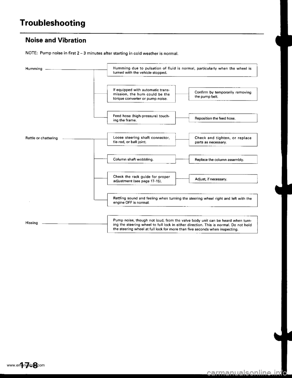
Noise and Vibration
NOTE: Pump noise in first 2 - 3 minutes after starting in cold weather is normal.
Humming
Rattle or chattering
Humming due to pulsation of fluid is normal, particularly when the wheel isturned with the vehicle stooDed.
lf equipped with automatic trans-mission, the hum could be thetorque converter or pump noase.
Confirm by temporarily removingthe pump belt.
Feed hose (high-pressure) touch-ing the frame.Beposition the feed hose.
Loose steering shaft connector,tie-rod, or balljoint.Check and tighten, or replaceparts as necessary,
Column shaft wobbling.Roplace the column assembly.
Check the rack guide for properadjustment (see page 17-15).Adjust, if necessary.
Rattling sound and feeling when turning the steering wheel right and left with th€engine OFF is normal.
Pump noise, though not loud, from the valve body unit can be heard when turn-ing the steering wheel to full lock in either direction. This is normal. Do not holdthe steering wheel at full lock lor more than five seconds when inspecting.
17-8
www.emanualpro.com
Page 855 of 1395
Troubleshooting
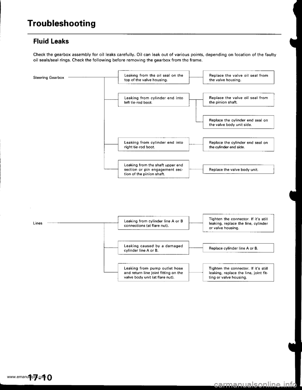
Fluid Leaks
Check the gearbox assembly for oil leaks carefully. Oil can leak out ot various points, depending on location of the faulty
oil seals/seal rings. Check the following before removing the gearbox from the frame.
Steering GearboxLeaking from the oil seal on thetop of the valve housing.Replace the valve oil seal fromthe valve housing.
Leaking from cylinder end intoleft tie rod boot.Replace the valve oil seal fromthe pinion shaft.
Replace the cylinder end seal onthe valve body unit side.
Leaking from cylinder end intoright tie-rod boot.Replace the cylinder end seal onthe cylinder end side.
Leaking lrom the shaft upper endsection or pin engagement sec-tion of the pinion shaft.Replace the valve body unit.
Tighten the connector. It it's stillleaking, replace the line, cylinderor valve housing.
Leaking from cylinder line A or Bconnections (at tlare nut).
Leaking caused by a damagedcylinder line A or B.Replace cylinder line A or B.
Leaking from pump outlet hoseand return line joint fitting on thevalve body unit {at tlare nut}.
Tighten the connector. ll it's stillleaking, replace the line, joint fit-ting or valve housing,
17-10
www.emanualpro.com
Page 862 of 1395
Pump Pressure Check With T/N 07406 -
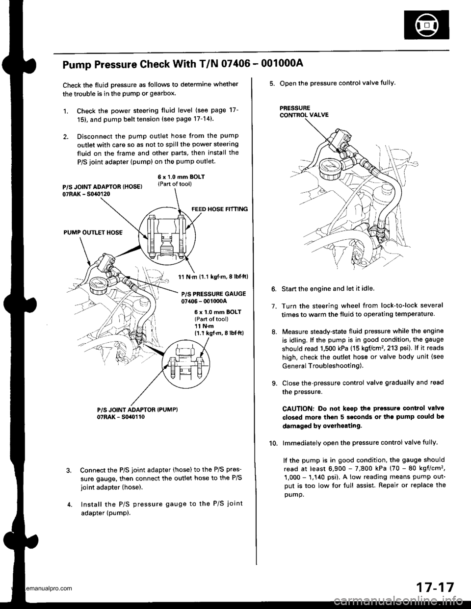
Check the fluid pressure as follows to determine whether
the trouble is in the pump or gearbox.
1. Check the power steering tluid level (see page 17-
151, and pump belt tension (see page 17-14).
2. Disconnect the pump outlet hose from the pump
outlet with care so as not to spill the power steering
fluid on the frame and other parts, then install the
P/S joint adapter (pump) on the pump outlet.
6 x 1.0 mm BOLT(Part oftool)
FEED HOSE HfNNG
PUMP OUTLET HOSE
1'l N.m 11.1 kgf.m,8lbf ft)
P/S PRESSURE GAUGE07406 - 001000A
6 x 1.0 mm BOLT(Part ol tool)11 N.m(1.r kg{.m,8lbf'ft|
Connect the P/S joint adapter (hose) to the P/S pres-
sure gauge, then connect the outlet hose to the P/S
joint adapter (hose).
Install the P/S pressure gauge to the P/S joint
adapter (pumpl.
001000A
5. Open the pressure controlvalve fully.
PRESSURECONTROL VALVE
7.
10.
Start the engine and let it idle.
Turn the steering wheel from lock-to-lock several
times to warm the tluid to operating temperature.
Measure steady-state fluid pressure while the engine
is idling. It the pump is in good condition, the gauge
should read 1,500 kPa (15 koflcm'�,213 psi). lf it reads
high. check the outlet hose or valve body unit {see
General Troubleshooting),
Close the-pressure control valve gradually and read
the oressure.
CAUTION: Do not keep the pressurs control valve
closed more then 5 seconds or the pump could bo
damaged by overheating.
lmmediately open the pressure controlvalve fully.
lf the pump is in good condition, the gauge should
read at least 6,900 - 7;800 kPa (70 - 80 kgflcm'�,
1,000 - 1.140 psi), A low reading means pump out-
Dut is too low for {ull assist. Repair or replace the
oumo.
17-17
www.emanualpro.com