Fluid leaking HONDA CR-V 1997 RD1-RD3 / 1.G Workshop Manual
[x] Cancel search | Manufacturer: HONDA, Model Year: 1997, Model line: CR-V, Model: HONDA CR-V 1997 RD1-RD3 / 1.GPages: 1395, PDF Size: 35.62 MB
Page 433 of 1395

Slave Cylinder
RemovaUlnstallation
CAUTION:
. Do nol spill brake tluid on the vehicle; itmaydamage
the paint; if brake fluid do€s contast the paint, wash
it off immediately with water.. Plug the end of the clutch line with a shop towel toprevcnt brake tluid from coming out.
.6|l,Super High Temp Urea crease (p/N 08798 -
9002).
: Brake Assembly Lube or equivalent rubber
grease.
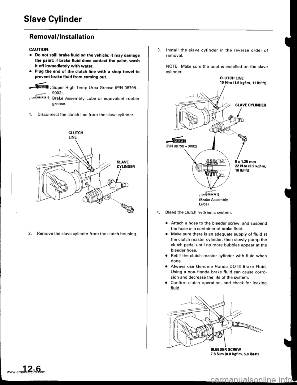
1. Disconnect the clutch line from the slave cvlinder.
2. Remove the slave cylinder from the clutch housing.
12-6
3. Install the slave cylinder in the reverse order ot
removal.
NOTEr Make sure the boot is installed on the slave
cylinder.
CLUTCH LINE15 N.m (i.S kgf.m, lt tbf.ftl
SLAVE CYLINDER
.-lG(P/N 08798 - 90021
E x 1.25 mm22 N.m (2.2 kgt.m,16 tbtft)
(Brake AssemblyLube)
Bleed the clutch hydraulic system.
Attach a hose to the bleeder screw, and suspend
the hose in a container of brake fluid.
Make sure there is an adequate supply of fluid at
the clutch master cylinder, then slowly pump the
clutch pedal until no more bubbles appear at the
bleeder hose.
Refill the clutch master cylinder with fluid whenqone.
Always use Genuine Honda DOT3 Brake Fluid.
Using a non Honda brake fluid can cause corro-
sion and decrease the life of the system.
Confirm clutch operation, and check for leaking
fluid.
7.8 N.m (0.8 kgf.m. 5.8 lbt.ft)BLEEDER SCREW
www.emanualpro.com
Page 818 of 1395

DriveshaftsFront Driveshafts
Inspection
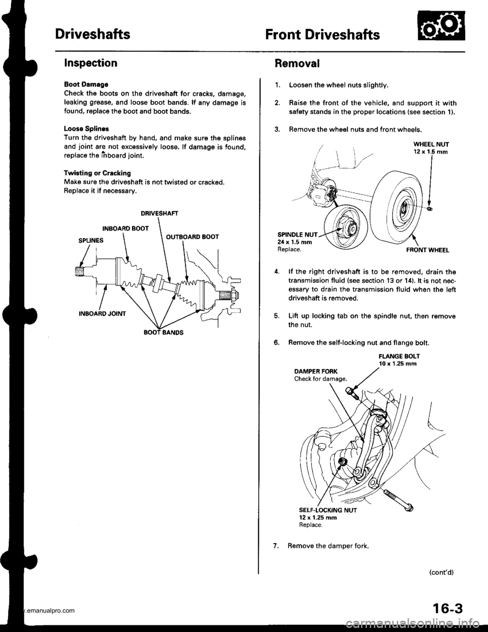
Boot Damago
Check the boots on the driveshaft for cracks, damago,
leaking grease, and loose boot bands. lf any damags is
found, replace the boot and boot bands.
Looso Splines
Turn the driveshaft by hand, and make sure th€ splin€s
and joint are not excessively loose. lf damage is found,
replace the inboard joint.
Twisting or Crscking
Make sure the driveshaft is not twisted or crackod.
Replace it if necessary.
DRIVESHAFT
1.
Removal
Loosen the wheel nuts slightly.
Raise the front of the vehicle, and suppon it with
safety stands in the proper locations (see section 1).
Remove the wheel nuts and front wheels.?
SPINDLE NUT24 x 1.5 mmReplace.
lf the right driveshaft is to be removed, drain the
transmission fluid {see s€ction 13 or 14). lt is not nec-
essary to drain the transmission fluid when the left
driveshaft is removed.
Lift up locking tab on the spindle nut, then remove
the nut,
Remove the self-locking nut and flange bolt,
FLANGE BOLT10 x 1.25 mm
FRONT WHEEL
(cont'd)
6.
SELF"LOCKING NUT12 x 1.25 mmReplace.
7. Remove the damper fork,
16-3
www.emanualpro.com
Page 855 of 1395

Troubleshooting
Fluid Leaks
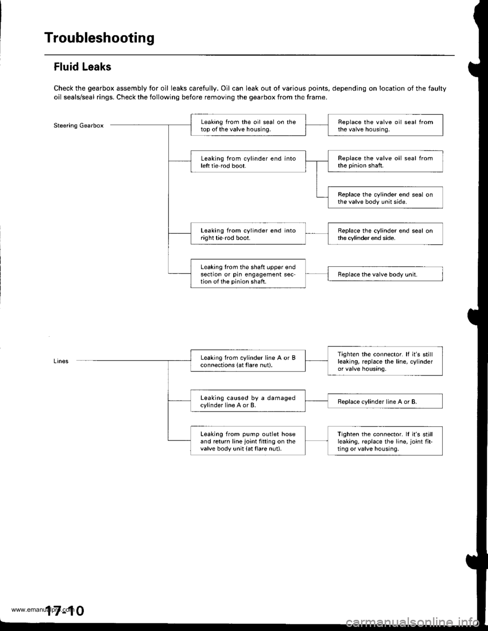
Check the gearbox assembly for oil leaks carefully. Oil can leak out ot various points, depending on location of the faulty
oil seals/seal rings. Check the following before removing the gearbox from the frame.
Steering GearboxLeaking from the oil seal on thetop of the valve housing.Replace the valve oil seal fromthe valve housing.
Leaking from cylinder end intoleft tie rod boot.Replace the valve oil seal fromthe pinion shaft.
Replace the cylinder end seal onthe valve body unit side.
Leaking from cylinder end intoright tie-rod boot.Replace the cylinder end seal onthe cylinder end side.
Leaking lrom the shaft upper endsection or pin engagement sec-tion of the pinion shaft.Replace the valve body unit.
Tighten the connector. It it's stillleaking, replace the line, cylinderor valve housing.
Leaking from cylinder line A or Bconnections (at tlare nut).
Leaking caused by a damagedcylinder line A or B.Replace cylinder line A or B.
Leaking from pump outlet hoseand return line joint fitting on thevalve body unit {at tlare nut}.
Tighten the connector. ll it's stillleaking, replace the line, joint fit-ting or valve housing,
17-10
www.emanualpro.com
Page 928 of 1395

Inspection and Adjustment
Brake System Rubber Parts and Brake Booster
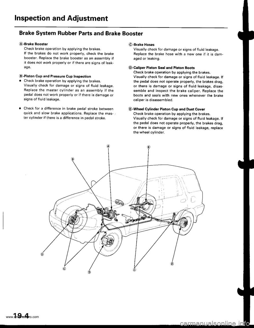
@-Brake Booster
Check brake operation by applying the brakes.
lf the brakes do not work properly, check the brake
booster. Replace the brake booster as an assembly ifit does not work properly or if there are signs of leak-
age.
@-Piston Cup and Pressure Cup Inspection. Check brake operation by applying the brakes.
Visually check for damage or signs of tluid leakage.Replace the master cylinder as an assembly if thepedal does not work properly or if there is damage orsigns of fluid leakage.
. Check for a difference in brake pedal stroke betweenquick and slow brake applications. Replace the mas-.
ter cylinder if there is a difference in pedal stroke.
(9-Brake Hoses
Visually check for damage or signs of fluid leakage.
Replace the brake hose with a new one if it is dam-
aged or leaking.
O-Caliper Piston S€al and Piston Boots
Check brake operation by applying the brakes.
Visually check for damage or signs of fluid leakage. lf
the pedal does not operate properly, the brakes drag,
or there is damage or signs of fluid leakage, disas-
semble and inspect the brake caliper. Replace the
boots and seals with new ones whenever the brake
caliper is disassembled.
@-Wheel Cylinder Piston Cup and Dust Cover
Check brake operation by applying the brakes.
Visually check for damage or signs of fluid leakage. lf
the pedal does not operate properly, the brakes drag,
or there is damage or signs of fluid leakage, replace
the wheel cvlinder.
19-4
www.emanualpro.com