Set timing HONDA CR-V 1997 RD1-RD3 / 1.G Workshop Manual
[x] Cancel search | Manufacturer: HONDA, Model Year: 1997, Model line: CR-V, Model: HONDA CR-V 1997 RD1-RD3 / 1.GPages: 1395, PDF Size: 35.62 MB
Page 51 of 1395
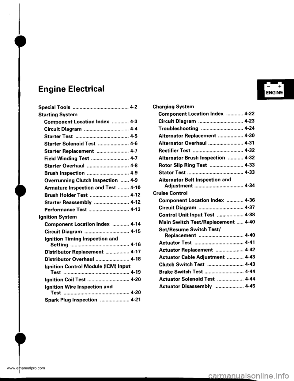
Engine Electrical
Speciaf Tools ............. 4-2
Starting System
Component Location Index ............ 4-3
Circuit Diagram ................................ 4-4
Starter Test ........... 4-5
Starter Solenoid Test ...................... 4'5
Starter Replacement ....................... 4-7
Field Winding Test ........................... 4-7
Starter Overhaul ............................,. 4-8
Brush Inspection ...........................,., 4-9
Overrunning Glutch Inspection ...... 4-9
Armature lnspection and Test ........4-10
Brush Holder Test ............................ 4-12
Starter Reassemb|y ......................... 4-1 2
Perf ormance Test ............................. 4- 1 3
lgnition System
Component Location Index ............ 4-14
Circuit Diagram ................................ 4-15
lgnition Timing Inspection and
Setting .......................................... 4-16
Distributor Replacement ........,........ 4-17
Distributor Overhaul .............,,......... 4-18
lgnition Control Module (lCM) Input
Test ..............................,................ 4-19
fgnition Coil Test .............................. 4-2O
lgnition Wire Inspection and
Test ............................................... 4-20
Spark Plug Inspection ..................... 4-21
-+
ENGINE
Charging System
Component Location Index ............ 4-22
Circuit Diagram ....................,........... 4-23
Troubleshooting .............................. 4-24
Alternator Replacement ..........,....... 4-30
Alternator Overhaul .......,,................ 4-31
Rectifier Test .........4-32
Alternator Brush Inspection ........... 4-32
Rotor Slip Ring Test ........................ 4-33
Stator Test ............. 4-33
Alternator Belt Inspection and
Adiustment ........4-34
Gruise Control
Component Location Index .,,,........ 4-36
Circuit Diagram ................................ 4-37
Control Unit Input Test ................... 4-38
Main Switch Test/Replacement ..... 4-40
Set/Resume Switch Test/
Replacement .......................,........ 4'40
Actuator Test ....,,., 4-41
Actuator Replacement ...............,.... 4-42
Actuator Cable Adiustment ............ 4-43
Clutch Switch Test .......................... 4-43
Brake Switch Test .................. .......... 4-44
Actuator Solenoid Test .............. ...,. 4-44
Actuator Disassembly ..................... 4-45
www.emanualpro.com
Page 66 of 1395

lgnition System
5.
lgnition Timing Inspection and Setting
2.
1.Check the idle speed, and adjust it if necessary (see
section 1 1).
Pull out the service check connector 2P (BRN and
BLK wires) from the connector holder located under
the dash on the front passenger side, then connect
the scs service connector (P/N 07PAz - 0010100) to
it.
Start the engine. Hold the engine at 3,000 rpm with
no load (A/T in N or E, Mff in neutral) until the
radiator fan comes on, then let it idle.
Connect the timing light to the No. I ignition wire,
then point the light toward the pointer on the timing
belt cover.
Check the ignition timing in no load conditions:
headlights, blower fan, rear window defogger, and
air conditioner are not operating.
lgnition Timing:
M/T: 16" 12" BTDC (RED) idling in neutral
AlTt'16" !2" BTDC (RED) idling in E or E
CRANKSHAFTPULLEY
4-16
6. lf necessary, adjust the ignition timing as follows.
Loosen the distributor mounting bolts, and turn the
distributor ignition (Dl) housing counterclockwise to
advance the timing or clockwise to retard the tim-
t no,
7.
8.
MOUNTING BOLTS24 N.m {2.4 kgf m, 17 lbtft}
Tighten the distributor mounting bolts, and recheck
the ignition timing.
Disconnect the SCS service connector from the ser-
vice check connector.
To RETARD
www.emanualpro.com
Page 67 of 1395
e
o
I'
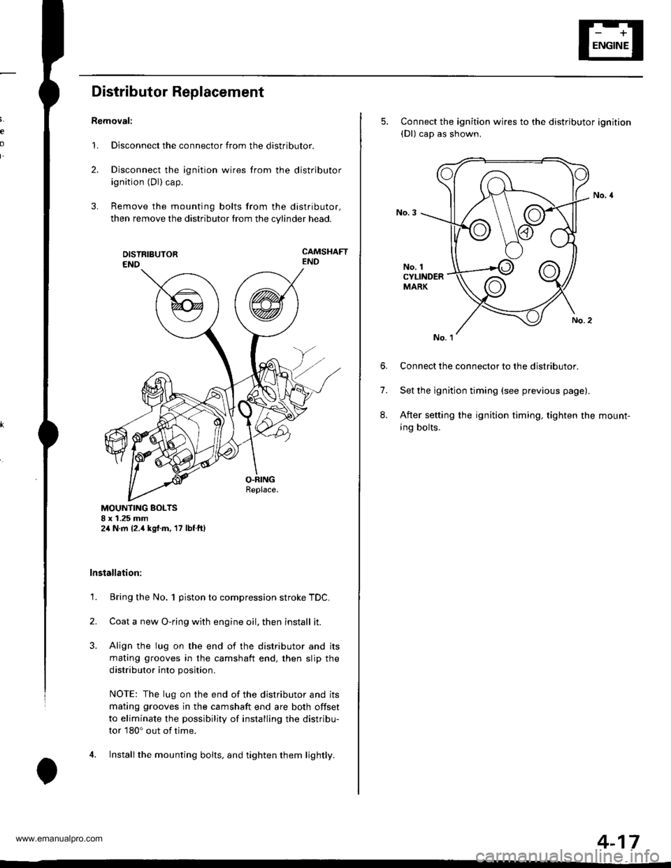
Distributor Replacement
Removal:
1. Disconnect the connector from the distributor.
2. Disconnect the ignition wires from the distributor
ignition (Dl) cap.
3. Remove the mounting bolts from the distributor,
then remove the distributor from the cylinder head.
CAMSHAFTEND
MOUNTING BOLTS8 x 1.25 mm2,1N.m {2.,1kgrf.m, 17 lbf ftl
lnstallation:
1. Bring the No. 1 piston to compression stroke TDC.
2. Coata new O-ring with engine oil, then install it.
3. Align the lug on the end of the distributor and its
mating grooves in the camshaft end, then slip the
distributor into position.
NOTE: The lug on the end of the distributor and its
mating grooves in the camshaft end are both offset
to eliminate the possibility of installing the distribu-
tor 180o out of time.
4. Installthe mounting bolts, and tighten them lightly.
5. Connect the ignition wires to the distributor ignition(Dl) cap as shown,
No. 1CYLINDERMARK
6. Connect the connector to the distributor.
7. Set the ignition timing (see previous page).
8. After setting the ignition timing, tighten the mount-
ing bolts.
4-17
www.emanualpro.com
Page 122 of 1395
1.
2.
Inspection
Remove the cylinder head cover.
lnspect the timing belt for c.acks and oil or coolant
soaking. Replace the belt if it is oil or coolant
soaked. Remove any oil or solvent that gets on the
belt.
lnspect thisarea for wear.
After inspecting, retorque the crankshaft pulley bolt
to 177 N.m (18.0 kgnm, 130 lbf.ft).
Install the cylinder head cover (see page 6-32).
3.
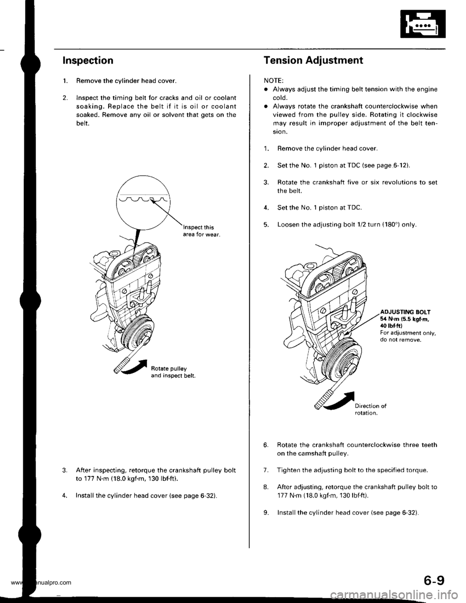
Tension Adjustment
NOTE:
. Always adjust the timing belt tension with the engine
coto.
. Always rotate the crankshaft counterclockwise when
viewed from the pulley side. Rotating it clockwise
may result in improper adiustment of the belt ten-
sion.
'1. Remove the cylinder head cover
2. Set the No. 1 piston at TDC (see page.6-12).
3. Rotate the crankshaft five or six revolutions to set
the belt.
Set the No. 1 piston at TDC.
Loosen the adjusting bolt 1/2 turn (180') only.
4.
5.
ADJUSTING BOLT5,4 N.m (5.5 kgf.m,40 tbtftlFor adiustment only,
7.
8.
Rotate the crankshaft counterclockwise three teeth
on the camshaft pulley.
Tighten the adjusting bolt to the specified torque.
After adjusting, retorque the crankshaft pulley bolt to
177 N.m (18.0 kgf.m, 130 lbf.ft).
Installthe cylinder head cover (see page 6-32).9.
rotation,
6-9
www.emanualpro.com
Page 124 of 1395
8. Remove the cylinder head cover.
NOTE: Refer to page 6-32 when installing the cylin-
der head cover.
Remove the crankshaft pulley (see page 6-7).
Remove the middle cover and lower cover. Do not
use these covers to store removed items.
9.
10.
11.
MTDDLE 6x1.0mm
COVER 9.8 N.m {1.0 kgt m,
LOWERCOVER
9.8 N.m (1.0 kgt.m, 7.2 lbf.ftl
Mark the direction of rotation on the timing belt.
Loosen the adjusting bolt 180'. Push the tensioner to
remove tension from the timing belt, then retighten
the adiusting bolt.
AINUSTING BOLT54 N.m (5,5 kgt m,.(} tbf.rrl
12.
13. Remove the timing belt.
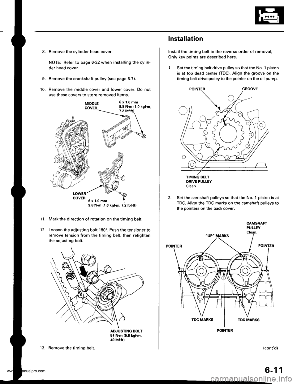
Installation
Install the timing belt in the reverse order of removal;
Only key points are described here,
1. Set the timing belt drive pulley so that the No. 1 piston
is at top dead center (TDC). Align the groove on the
timing belt drive pulley to the pointer on the oil pump.
GROOVE
DRIVE PULLEYClean.
2. Set the camshaft pulleys so that the No. I piston is at
TDC. Align the TDC marks on the camshaft pulleys to
the pointers on the back cover.
POINTER
CAMSHAFTPULLEYClean.
POINTER
r-t
(cont'd)
6-11
www.emanualpro.com
Page 145 of 1395

Cylinder Head
Installation (cont'dl
'13. Align the marks on the cylinder head plug to thecylinder head upper surface, then install the cylin
der head plug in the end of the cylinder head.
CYLINOER HEADPLUGReplace.
lnstallthe back cover.
To set the camshafts at TDC position for the No. lpiston, align the holes in the camshafts with theholes in the No. l camshaft holders and insert 5.0mm pin punches in the holes. Install the keys into
the camshaft grooves.
37 N m (3.8 *gl.m, 27 lbt.tr)
9.8 N.m (1.0 kgtm,7.2|hrftl
Push the camshaft pulleys onto the camshafts. thentighten the retaining bolts to the torque specified.
6-32
14.
KEYS
I x 1.25 mm
6x1.0mm
Install the timing belt (see page 6-1 1).
Adjust the valve clearance (see page 6-3).
Thoroughly clean the head cover gasket and thegroove.
lnstall the head cover gasket in the groove of thecylinder head cover. Seat the head cover gasket in
the recesses for the camshaft first, then work it into
the groove around the outside edges. Make sure thehead cover gasket is seated securely in the corners
of the recesses with no gap.
17.
'18.
19.
www.emanualpro.com
Page 166 of 1395
PistonsCrankshaft
Installation
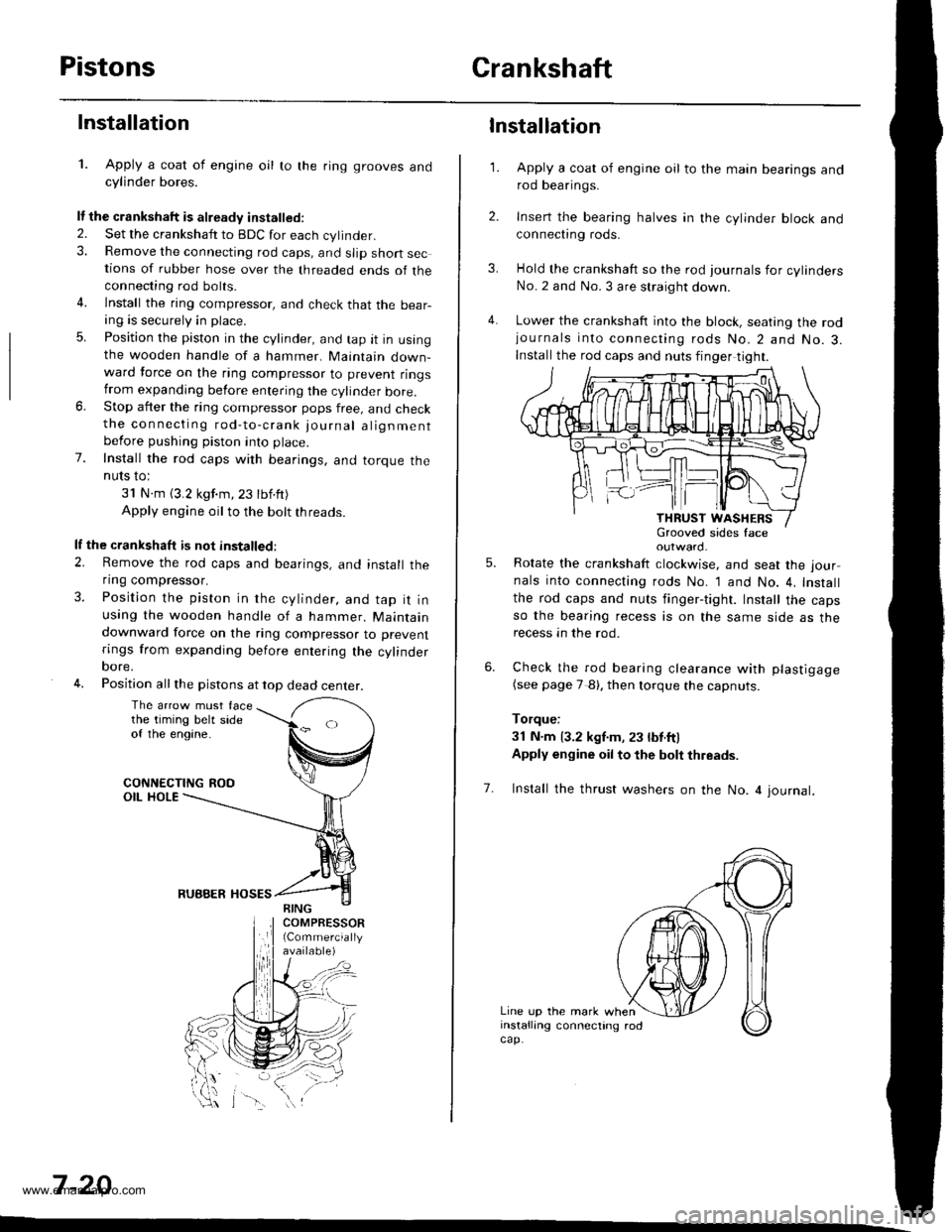
1. Apply a coat of engine oil to the ring grooves andcylinder bores.
It the crankshaft is already installed.
2. Set the crankshatt to BDC for each cylinder.3. Remove the connecting rod caps, and slip short sections of rubber hose over the threaded ends of theconnecting rod bolts.
4. lnstall the ring compressor, and check that the bear-ang is securely in place.
5. Position the piston in the cylinder, and tap it in usingthe wooden handle of a hammer. Maintain down-ward force on the ring compressor to prevent ringstrom expanding before entering the cylinder bore.6. Stop after the ring compressor pops free, and checkthe connecting rod-to-crank journal alignmentbefore pushing piston into place.
7. Install the rod caps with bearings, and torque theNUIS IO:
31 N.m (3.2 kgf.m,23 tbf.ft)
Apply engine oil to the bolt threads.
lf the crankshaft is not installed:
2. Remove the rod caps and bearings, and install theflng compressor.
3. Position the piston in the cylinder, and tap it inusing the wooden handle of a hammer. Maintaindownward force on the ring compressor to prevent
rings from expanding before entering the cylinderoore,
4. Position all the pistons at top dead center.
The arrow must facethe timing belt sideof the engine.
CONNECTING ROOOIL HOLE
RUBBER HOSES
7 -20
\-\
3.
4.
1.
6.
Installation
Apply a coat of engine oil to the main bearings androd bearings.
Insert the bearing halves in the cylinder block andconnect|ng rods.
Hold the crankshaft so the rod journals for cylindersNo.2 and No. 3 are straight down.
Lower the crankshaft into the block, seating the rodjournals into connecting rods No.2 and No.3.Install the rod caps and nuts finger tight.
outward.
Rotate the crankshaft clockwise, and seat the jour
nals into connecting rods No. 1 and No. 4, Install
the rod caps and nuts finger-tight. Install the capsso the bearing recess is on the same side as therecess an the rod.
Check the rod bearing clearance with plastigage(see page 7 8). then lorque the capnuts.
Torque:
3l N.m 13.2 kgf.m, 23 lbt.ftl
Apply engine oil to the bolt thleads.
5.
7. Install the thrust washers on the No. 4 journal.
Line up the mark wheninstalling connecting rodcap.
www.emanualpro.com
Page 179 of 1395
1.
2.
3.
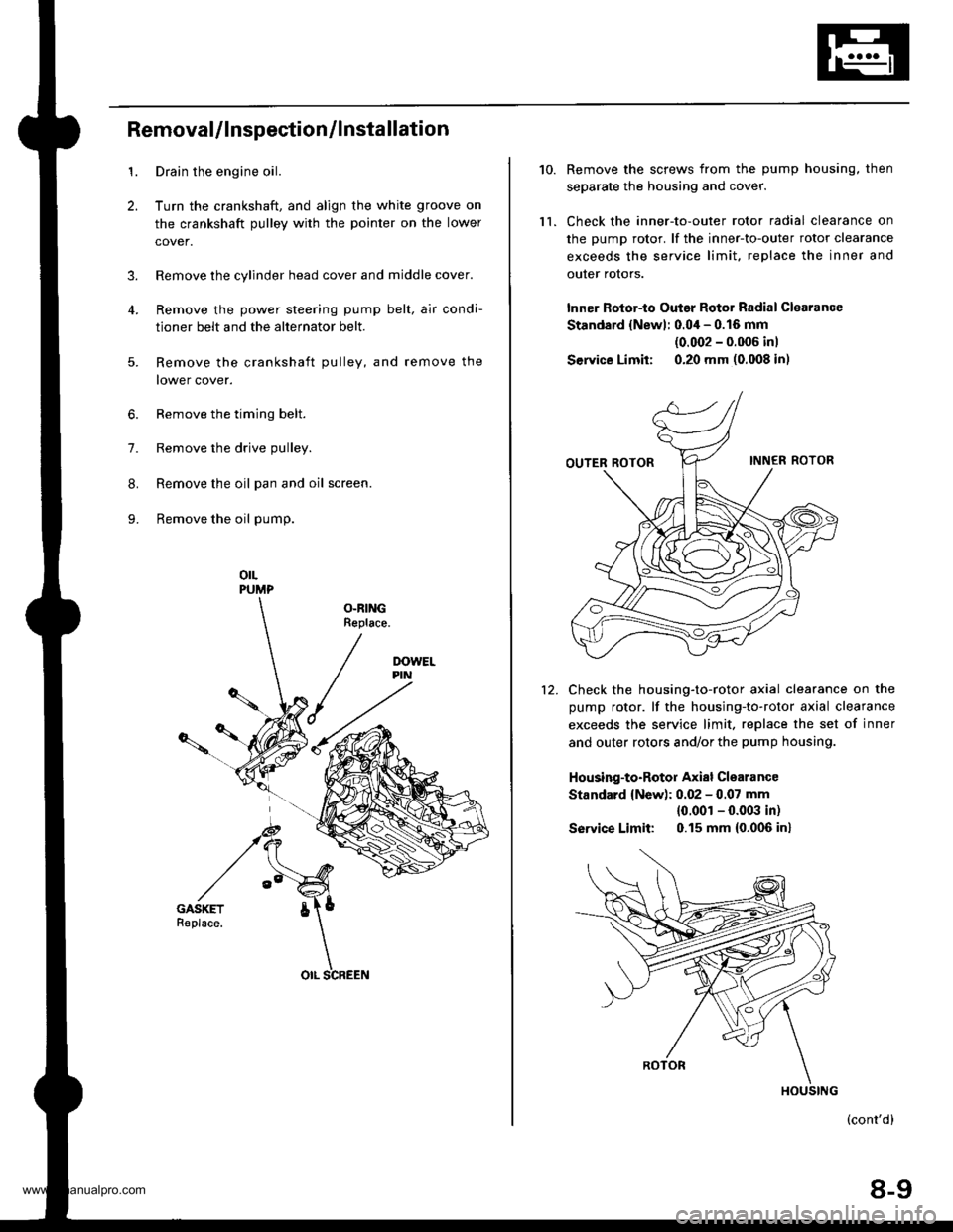
RemovaUlnspection/lnstallation
Drain the engine oil.
Turn the crankshaft, and align the white groove on
the crankshaft pulley with the pointer on the lower
cover.
Remove the cylinder head cover and middle cover.
Remove the power steering pump belt, air condi-
tioner belt and the alternator belt.
Remove the crankshaft pulley, and remove the
lower cover.
6. Remove the timing belt.
7. Remove the drive pulley.
8. Remove the oil pan and oil screen.
9. Remove the oil pump.
orLPUMP
OLRINGReplace.
5.
OIL SCREEN
10.
ll.
Remove the screws from the pump housing, then
separate the housing and cover.
Check the inner-to-outer rotor radial clearance on
the pump rotor. lf the inner-to-outer rotor clearance
exceeds the service limit. replace the inner and
outer rotors.
lnner Rotor-to Outar Rotor Radial Clearance
Standard {Newl: 0.04 - 0.16 mm
{0.002 - 0.006 inl
Service Limit: 0.20 mm (0.008 in)
Check the housing-to-rotor axial clearance on the
pump rotor. lf the housing-to-rotor axial clearance
exceeds the service limit. replace the set of inner
and outer rotors and/or the pump housing.
Housing-to-Rotor Axial Clearance
Standard {New): 0.02 - 0.07 mm
{0.001 - 0.003 in)
So|'�ice Limit: 0.15 mm (0.006 inl
(cont'd)
8-9
HOUSING
www.emanualpro.com
Page 268 of 1395
Troubleshooting
Troubleshooting Procedures (cont'd)
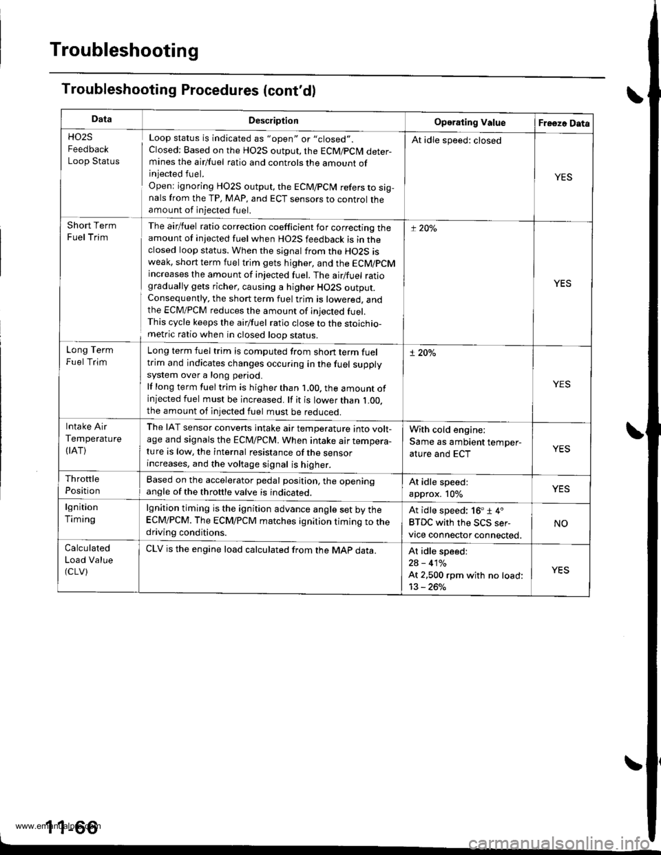
DataDescliptionOperating ValueFreezo Data
HO2S
Feedback
Loop Status
Loop status is indicated as "open" or "closed".
Closed: Based on the HO2S output, the ECM/pCM deter-mines the airlfuel ratio and controls the amount ofinjected fuel.
Open: ignoring HO2S output, the ECM/pCiM refers to sig,nals from the TP, MAP, and ECT sensors to control theamount of injected fuel.
At idle speed: closed
YES
Short Term
Fuel Trim
The airlfuel ratio correction coefficient for correcting theamount of injected fuel when HO2S feedback is in theclosed loop status. When the signal from the HO2S isweak, short term fuel trim gets higher, and the ECM/PCMincreases the amount of injected fuel. The airlfuel ratiogradually gets richer, causing a higher HO2S output.Consequently. the short term fuel trim is lowered. andthe ECM/PCM reduces the amount of injected fuel.This cycle keeps the airfuel ratio close to the stoichio-metric ratio when in closed looD status.
t:20y"
YES
Long Term
Fuel Trim
Long term fuel trim is computed from shon term fueltrim and indicates changes occuring in the fuel supplysystem over a long period.
lf long term fuel trim is higher than 1,00. the amount ofinjected fuel must be increased. lf it is lower than L00.the amount of injected fuel must be reduced.
! 20%
Intake Air
Temperature
(IAT)
The IAT sensor converts intake air temperature into volt-age and signals the ECrU/PCM. When intake air tempera-ture is low, the internal resistance of the sensorincreases, and the voltage signal is higher.
With cold engine:
Same as ambient temper-
ature and ECTYES
Throttle
Position
Based on the accelerator pedal position, the openingangle of the throttle valve is indicateo.At idle speed:
approx. 10%
lgnition
Timing
lgnition timing is the ignition advance angle set by theECM/PCM. The ECM/PCM matches ignition timing to thedriving conditions.
At idle speed: 16'1 4.
BTDC with the SCS ser-
vtce connector connected.
NO
Calculated
Load Value(cLV)
CLV is the engine load calculated from the MAp data.At idle speed:
2A - 410/o
At 2,500 rpm with no load:
13 - 260/o
YES
_
1 1_66
www.emanualpro.com
Page 282 of 1395

PGM-FI System
System Description
INPUTS
CKP/TDC/CYP Sensor
CKF Sensor
MAP Sensor
ECT Sensor
IAT Sensor
TP Sensor
Primary HO2S
Secondary H02S
vss
KS*5
BARO Sensor
ELD*6
Starter Signal
ALT FR Signal
Air Conditioning Signal
Ay'T Gear Position Signal*1
Baftery Voltage (lGN.1)
Brake Switch Signal
PSP Switch Signal
Fuel Tank Pressuae Sensor*4. *5
Countershaft Speed Sensor*1
Mainshaft Speed Sensor*r
OVER-DRIVE Switch Signal*s
ENGINE CONTROL MODULE (ECM)/
POWERTRAIN CONTROL MODULE (PCM) OUTPUTS
|iuel 1"j""- Th,rhg ""d Drrafr";-l
Et*-.nt"tdt"cont.orl
to,r*,c;;trffi;]
l.----.---:. .Lrgnrnon |lmrng Lonrror I
Ecir/PcM B*k',p Fr""il]
m;"t-ll-r*'io*l
Fuel Injectors
PGM-Fl Main Relay (Fuel Pump)
MIL
IAC Valve
Ay'C Compressor Clutch Relay
Radiator Fan Relay
Condenser Fan Relay
ALT
tcM
EVAP Purge Control Solenoid
Valve
Primary HO2S Heater
Secondary H02S HeaterEVAP Bypass Solenoid Valve*a *5
EVAP Control Canister Vent Shut
DLC
Lock-up Control Solenoid Valve*l
Shift Control Solenoid Valve*1
Ay'T Clutch Pressure Control
Solenoid Valve*1
D4 Indicator Light'1 *3, *a
D Indicator Light,l *5
OVER-DRIVE OFF Indicator
Lighl*t *:
*1: A/T {3:'97 model'2: M/f +4:'98 model*5: '99 - 00 models"6: USA
PGM-Fl System
The PGM-Fl system on this model is a sequential multiport fuel injection system.
Fuel iniecior Timing and Duration
The ECM/PCM contains memories for the basic discharge durations at various engine speeds and manifold pressure. The
basic discharge duration, after being read out from the memory, is further modified by signals sent from various sensors
to obtain the final discharge duration.
ldle Air Control
ldle Air Control Valve (lAC Valve)
When the engine is cold, the Ay'C compressor is on, the transmission is in gear, the brake pedal is depressed, the P/S load
is high, or the alternator is charging, the ECM/PCM controls current to the IAC Valve to maintain the correct idle speed.
lgnition Timing Control
o The ECM/PCM contains memories for basic ionition timing at various engine speeds and manifold air flow rates.
lgnition timing is also adjusted for engine coolant temperature.
. A knock control system was adopted which sets the ideal ig nition timing for the octane rating of the gasoline used.*s
Other Control Funstions
1. Starting Control
When the engine is started. the ECM/PCM provides a rich mixture by increasing fuel injector duration.
2. Fuel Pump Control
. When the ignition switch is initially turned on (ll). the ECMiPCM suppli€s ground to the PGM-FI main relay that
supplies current to the fuel pump for two seconds to pressurize the fuel system.
. When the engine is running, the ECM/PCM supplies ground to the PGM-FI main relay that supplies current to the
fuel oumo.
. When the engine is not running and the ignition is on, the ECM/PCM cuts ground to the PGM-FI main relay which
cuts current to the fuel pump.
1 1-80
www.emanualpro.com